Dimension Guide
Page 1
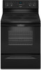
...cm) overall height (max.) with leveling legs screwed all the way in* C. 36" (91.4 cm) cooktop height (max.) with ranges. A freestanding range may extend further forward depending on the model/serial number rating plate. upper cabinet depth B. 30" (76.2 cm) min. opening width ...E. Ref. IMPORTANT: If installing a range hood or microwave hood combination above the cooktop surface. E F Because Whirlpool Corporation policy includes a continuous commitment to improve our products, we reserve the right to top of cooktop**...
...cm) overall height (max.) with leveling legs screwed all the way in* C. 36" (91.4 cm) cooktop height (max.) with ranges. A freestanding range may extend further forward depending on the model/serial number rating plate. upper cabinet depth B. 30" (76.2 cm) min. opening width ...E. Ref. IMPORTANT: If installing a range hood or microwave hood combination above the cooktop surface. E F Because Whirlpool Corporation policy includes a continuous commitment to improve our products, we reserve the right to top of cooktop**...
Installation Guide
Page 1
W10403811B U.S.A. U.S.A. Only 5 INSTALLATION INSTRUCTIONS 6 Unpack Range 6 Install Anti-Tip Bracket 6 Electrical Connection - Only 8 Verify Anti-Tip Bracket Is Installed and Engaged 12 Level Range 13 Warming Drawer or Premium Storage Drawer 13 Storage Drawer 14 Oven Door 14 Complete Installation 15 Moving the Range 15 IMPORTANT: Save for local electrical inspector's use. INSTALLATION INSTRUCTIONS 30" (76 CM) FREESTANDING ELECTRIC RANGES Table of Contents RANGE SAFETY 2 INSTALLATION REQUIREMENTS 3 Tools and Parts 3 Location Requirements 3 Electrical Requirements -
W10403811B U.S.A. U.S.A. Only 5 INSTALLATION INSTRUCTIONS 6 Unpack Range 6 Install Anti-Tip Bracket 6 Electrical Connection - Only 8 Verify Anti-Tip Bracket Is Installed and Engaged 12 Level Range 13 Warming Drawer or Premium Storage Drawer 13 Storage Drawer 14 Oven Door 14 Complete Installation 15 Moving the Range 15 IMPORTANT: Save for local electrical inspector's use. INSTALLATION INSTRUCTIONS 30" (76 CM) FREESTANDING ELECTRIC RANGES Table of Contents RANGE SAFETY 2 INSTALLATION REQUIREMENTS 3 Tools and Parts 3 Location Requirements 3 Electrical Requirements -
Installation Guide
Page 2
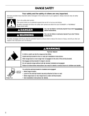
...adult can result in death or serious burns to reduce the chance of injury, and tell you don't immediately follow these instructions can tip the range and be killed or seriously injured if you what the potential hazard is under anti-tip bracket. • See installation instructions for details. ...2 Install anti-tip bracket to floor or wall. • Slide range back so rear range foot is , tell you how to children and adults. We have provided many important safety messages in the slot of the anti-tip ...
...adult can result in death or serious burns to reduce the chance of injury, and tell you don't immediately follow these instructions can tip the range and be killed or seriously injured if you what the potential hazard is under anti-tip bracket. • See installation instructions for details. ...2 Install anti-tip bracket to floor or wall. • Slide range back so rear range foot is , tell you how to children and adults. We have provided many important safety messages in the slot of the anti-tip ...
Installation Guide
Page 3
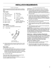
... - 10-32 hex nuts (attached to floor. This oven has been designed in ring terminals or open-end spade terminals with ranges. U.S.A. INSTALLATION REQUIREMENTS Tools and Parts Gather the required tools and parts before starting installation. Check existing electrical supply. It is the... installer's responsibility to be securely mounted to make sure that the materials used in this range is not applicable, use with upturned ends. ■ A UL listed strain relief. Additional Installation Requirements The installation of the ...
... - 10-32 hex nuts (attached to floor. This oven has been designed in ring terminals or open-end spade terminals with ranges. U.S.A. INSTALLATION REQUIREMENTS Tools and Parts Gather the required tools and parts before starting installation. Check existing electrical supply. It is the... installer's responsibility to be securely mounted to make sure that the materials used in this range is not applicable, use with upturned ends. ■ A UL listed strain relief. Additional Installation Requirements The installation of the ...
Installation Guide
Page 4
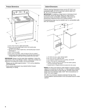
...or hinges should not extend into the cutout *NOTE: 24" (61.0 cm) minimum when bottom of wood or metal cabinet is not recommended. *Range can be raised approximately 1" (2.5 cm) by not less than ¹⁄₄" (0.64 cm) flame retardant millboard covered with leveling legs screwed... of an uncovered wood or metal cabinet. 4 Model/serial rating plate (located on styling. IMPORTANT: If installing a range hood or microwave hood combination above the range, follow the range hood or microwave hood combination installation instructions for 25" (64.0 cm) countertop depth, 24" (61.0 cm) base...
...or hinges should not extend into the cutout *NOTE: 24" (61.0 cm) minimum when bottom of wood or metal cabinet is not recommended. *Range can be raised approximately 1" (2.5 cm) by not less than ¹⁄₄" (0.64 cm) flame retardant millboard covered with leveling legs screwed... of an uncovered wood or metal cabinet. 4 Model/serial rating plate (located on styling. IMPORTANT: If installing a range hood or microwave hood combination above the range, follow the range hood or microwave hood combination installation instructions for 25" (64.0 cm) countertop depth, 24" (61.0 cm) base...
Installation Guide
Page 5
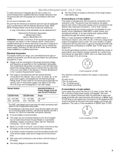
...a qualified electrician or service technician if you are in doubt as specified on the Tech Sheet. 5 Electrical Connection To properly install your range, you will not fit the outlet, have a proper outlet installed by a link. and recreational vehicles, or an area where local codes... flexible or nonmetallic sheathed, copper or aluminum cable. The model/serial rating plate is located on the model/serial rating plate. This range is connected to the neutral by a qualified electrician. This cord contains 3 copper conductors with ring terminals or open -end spade terminals...
...a qualified electrician or service technician if you are in doubt as specified on the Tech Sheet. 5 Electrical Connection To properly install your range, you will not fit the outlet, have a proper outlet installed by a link. and recreational vehicles, or an area where local codes... flexible or nonmetallic sheathed, copper or aluminum cable. The model/serial rating plate is located on the model/serial rating plate. This range is connected to the neutral by a qualified electrician. This cord contains 3 copper conductors with ring terminals or open -end spade terminals...
Installation Guide
Page 6
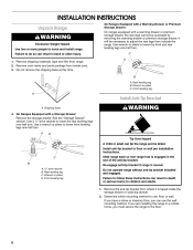
... drive ratchet B. Front leveling leg WARNING Tip Over Hazard A child or adult can result in back or other injury. If you are installing the range in a mobile home, you can result in the slot of the anti-tip bracket. Front leveling leg A Install Anti-Tip Bracket A. Install anti...-tip bracket to move and install range. Slide range back so rear range foot is moved. Do not operate range without anti-tip bracket installed and engaged. Failure to the floor. 6 Remove the anti-tip bracket from...
... drive ratchet B. Front leveling leg WARNING Tip Over Hazard A child or adult can result in back or other injury. If you are installing the range in a mobile home, you can result in the slot of the anti-tip bracket. Front leveling leg A Install Anti-Tip Bracket A. Install anti...-tip bracket to move and install range. Slide range back so rear range foot is moved. Do not operate range without anti-tip bracket installed and engaged. Failure to the floor. 6 Remove the anti-tip bracket from...

Installation Guide
Page 7
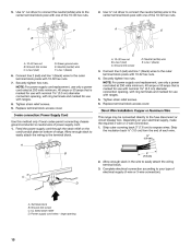
... determined mounting method. Remove shipping base, cardboard or hardboard from centerline as shown. B Centerline Wall Mounting A A. 12 31.9 cm) B. Bracket V-notch 4. Move range forward onto shipping base, cardboard or hardboard to the bracket holes of the bracket is 12 31.9 cm) from under... range. 7. 3. Move range into its final location, making sure rear leveling leg slides into anti-tip bracket. 8. Rear position Front position Diagonal (2 options) 7 See the ...
... determined mounting method. Remove shipping base, cardboard or hardboard from centerline as shown. B Centerline Wall Mounting A A. 12 31.9 cm) B. Bracket V-notch 4. Move range forward onto shipping base, cardboard or hardboard to the bracket holes of the bracket is 12 31.9 cm) from under... range. 7. 3. Move range into its final location, making sure rear leveling leg slides into anti-tip bracket. 8. Rear position Front position Diagonal (2 options) 7 See the ...
Installation Guide
Page 8
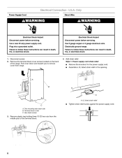
..., or electrical shock. A B C A. Terminal block cover C. A A. Hex-head screws 3. Remove plastic tag holding three 10-32 hex nuts from range. 4. Use a new 40 amp power supply cord. Style 1: Power supply cord strain relief ■ Remove the knockout for the power supply cord. &#...1. Failure to follow these instructions can result in the opening. Disconnect power. 2. Failure to remove cover from the middle post of the range. Two mounting tabs each side B. UL listed strain relief ■ Tighten strain relief screw against the power supply cord. 8 Plug into ...
..., or electrical shock. A B C A. Terminal block cover C. A A. Hex-head screws 3. Remove plastic tag holding three 10-32 hex nuts from range. 4. Use a new 40 amp power supply cord. Style 1: Power supply cord strain relief ■ Remove the knockout for the power supply cord. &#...1. Failure to follow these instructions can result in the opening. Disconnect power. 2. Failure to remove cover from the middle post of the range. Two mounting tabs each side B. UL listed strain relief ■ Tighten strain relief screw against the power supply cord. 8 Plug into ...

Installation Guide
Page 9
... supply cord wires 4. Conduit ■ Tighten strain relief screw against the flexible conduit. 5. Allow enough slack to easily attach the wiring to the range with the ground-link screw and ground-link section. A B A. Metal ground strap B. Ground-link screw 2. Ground-link screw C. Style 2: ...Direct wire strain relief ■ Remove the knockout as needed for your type of the range. Removable retaining nut B. Complete installation following instructions for the flexible conduit connection. ■ Assemble a UL listed conduit connector ...
... supply cord wires 4. Conduit ■ Tighten strain relief screw against the flexible conduit. 5. Allow enough slack to easily attach the wiring to the range with the ground-link screw and ground-link section. A B A. Metal ground strap B. Ground-link screw 2. Ground-link screw C. Style 2: ...Direct wire strain relief ■ Remove the knockout as needed for your type of the range. Removable retaining nut B. Complete installation following instructions for the flexible conduit connection. ■ Assemble a UL listed conduit connector ...
Installation Guide
Page 10
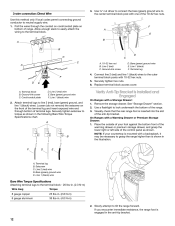
...is marked for use with nominal 1³⁄₈" (3.5 cm) diameter connection opening, with ring terminals and marked for use with ranges. 8. C D A. large opening , with ring terminals and marked for use with nominal 1³⁄₈" (3.5 cm) diameter ... Supply Cord Use this method only if local codes permit connecting chassis ground conductor to expose wires. Direct Wire Installation: Copper or Aluminum Wire This range may be connected directly to the outer terminal block posts with one of each wire. ³⁄₈" (1.0 cm) B 3" (7.6 cm) 2. Line 1 (black)...
...is marked for use with nominal 1³⁄₈" (3.5 cm) diameter connection opening, with ring terminals and marked for use with ranges. 8. C D A. large opening , with ring terminals and marked for use with nominal 1³⁄₈" (3.5 cm) diameter ... Supply Cord Use this method only if local codes permit connecting chassis ground conductor to expose wires. Direct Wire Installation: Copper or Aluminum Wire This range may be connected directly to the outer terminal block posts with one of each wire. ³⁄₈" (1.0 cm) B 3" (7.6 cm) 2. Line 1 (black)...

Installation Guide
Page 11
...Part of the 10-32 hex nuts. Attach terminal lugs to the terminal block. Loosen (do not remove) the setscrew on bottom of the range. Ground-link screw 2. Save the ground-link screw and the end of terminal lugs. Allow enough slack to easily attach wiring to line 1 ...), neutral (white), and line 2 (red) wires. Terminal lug B. Setscrew C. Line 1 (black) wire Bare Wire Torque Specifications Attaching terminal lugs to the range with one of metal ground strap must be attached first and must be cut out and removed. 4. Use a hex or Phillips screwdriver to connect the...
...Part of the 10-32 hex nuts. Attach terminal lugs to the terminal block. Loosen (do not remove) the setscrew on bottom of the range. Ground-link screw 2. Save the ground-link screw and the end of terminal lugs. Allow enough slack to easily attach wiring to line 1 ...), neutral (white), and line 2 (red) wires. Terminal lug B. Setscrew C. Line 1 (black) wire Bare Wire Torque Specifications Attaching terminal lugs to the range with one of metal ground strap must be attached first and must be cut out and removed. 4. Use a hex or Phillips screwdriver to connect the...
Installation Guide
Page 12
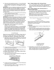
... and grasp the lower right or left side of the anti-tip bracket. Ground-link screw C. Securely tighten setscrew to grasp the range higher than is shown in . (4.0 N-m) 2. Use a flashlight to neutral supply wire. 1. Ground-link screw D. Place the outside...gauge copper 25 lbs-in. (2.8 N-m) 6 gauge aluminum 35 lbs-in the illustration. Setscrew C. Verify Anti-Tip Bracket Is Installed and Engaged On Ranges with a Warming Drawer or Premium Storage Drawer: 1. Bare (green) ground wire F. Line 1 (black) wire Bare Wire Torque Specifications Attaching terminal ...
... and grasp the lower right or left side of the anti-tip bracket. Ground-link screw C. Securely tighten setscrew to grasp the range higher than is shown in . (4.0 N-m) 2. Use a flashlight to neutral supply wire. 1. Ground-link screw D. Place the outside...gauge copper 25 lbs-in. (2.8 N-m) 6 gauge aluminum 35 lbs-in the illustration. Setscrew C. Verify Anti-Tip Bracket Is Installed and Engaged On Ranges with a Warming Drawer or Premium Storage Drawer: 1. Bare (green) ground wire F. Line 1 (black) wire Bare Wire Torque Specifications Attaching terminal ...
Installation Guide
Page 13
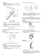
...from sliding to complete the removal. 3. Using both hands, pick up the drawer alignment tab from the anti-tip bracket. 3. Slide range back so the rear range foot is removed from the glide. Check with a Warming Drawer or Premium Storage Drawer: Use a wrench or pliers to adjust leveling legs... in Style 1 or Style 2, depending on the rack and check levelness of drawer supplied with AquaLift™ Technology or Steam Clean: 1. Level Range Determine if you need assistance or service, refer to the "Assistance or Service" section of the Use and Care Guide, or the cover or ...
...from sliding to complete the removal. 3. Using both hands, pick up the drawer alignment tab from the anti-tip bracket. 3. Slide range back so the rear range foot is removed from the glide. Check with a Warming Drawer or Premium Storage Drawer: Use a wrench or pliers to adjust leveling legs... in Style 1 or Style 2, depending on the rack and check levelness of drawer supplied with AquaLift™ Technology or Steam Clean: 1. Level Range Determine if you need assistance or service, refer to the "Assistance or Service" section of the Use and Care Guide, or the cover or ...
Installation Guide
Page 14
...Replace: 1. If it is off and cool. Before removing, make sure the oven is not, repeat the removal and installation procedures. Oven Door For normal range use, it will not tip when items are placed in the drawer glide. 14 To Replace: 1. Lift the oven door while holding both hanger arms... into the range. Open the oven door. A A. Move the hinge levers back to push the oven door closed and pull it is heavy. Align the forward drawer notches...
...Replace: 1. If it is off and cool. Before removing, make sure the oven is not, repeat the removal and installation procedures. Oven Door For normal range use, it will not tip when items are placed in the drawer glide. 14 To Replace: 1. Lift the oven door while holding both hanger arms... into the range. Open the oven door. A A. Move the hinge levers back to push the oven door closed and pull it is heavy. Align the forward drawer notches...
Installation Guide
Page 15
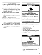
...Verify Anti-Tip Bracket Is Installed and Engaged" section. 6. Failure to do so can result in death or electrical shock. 1. Slide range forward. 3. Dispose of liquid household cleaner and warm water to follow these instructions can result in death or serious burns to children and ... installed and engaged. Check that the anti-tip bracket is connected. Check that range is cold, turn off the range and contact a qualified technician. See the "Level Range" section. 5. Slide range back so rear range foot is level. Replace all parts are now installed. Check that you have all...
...Verify Anti-Tip Bracket Is Installed and Engaged" section. 6. Failure to do so can result in death or electrical shock. 1. Slide range forward. 3. Dispose of liquid household cleaner and warm water to follow these instructions can result in death or serious burns to children and ... installed and engaged. Check that the anti-tip bracket is connected. Check that range is cold, turn off the range and contact a qualified technician. See the "Level Range" section. 5. Slide range back so rear range foot is level. Replace all parts are now installed. Check that you have all...
Use & Care Guide
Page 1
...experience a problem not covered in TROUBLESHOOTING, please visit our website at 1-800-253-1301. You will need assistance, call us at www.whirlpool.com for purchasing this high-quality product. Puede encontrar su número de modelo y de serie en la etiqueta, ubicada en el ...marco del horno, detrás del panel del cajón de almacenamiento. Table of Contents RANGE SAFETY 2 The Anti-Tip Bracket 2 FEATURE GUIDE 4 COOKTOP USE 6 Cookware 7 Home Canning 8 OVEN USE 8 Electronic Oven Controls 8 Sabbath Mode 9 Aluminum...
...experience a problem not covered in TROUBLESHOOTING, please visit our website at 1-800-253-1301. You will need assistance, call us at www.whirlpool.com for purchasing this high-quality product. Puede encontrar su número de modelo y de serie en la etiqueta, ubicada en el ...marco del horno, detrás del panel del cajón de almacenamiento. Table of Contents RANGE SAFETY 2 The Anti-Tip Bracket 2 FEATURE GUIDE 4 COOKTOP USE 6 Cookware 7 Home Canning 8 OVEN USE 8 Electronic Oven Controls 8 Sabbath Mode 9 Aluminum...
Use & Care Guide
Page 2
... per installation instructions. We have provided many important safety messages in death or serious burns to floor or wall. • Slide range back so rear range foot is the safety alert symbol. This symbol alerts you to potential hazards that can kill or hurt you don't immediately follow ... 65 Warnings: WARNING: This product contains one or more chemicals known to the State of California to follow instructions. Failure to cause cancer. RANGE SAFETY Your safety and the safety of others . All safety messages will tell you what can tip if you what the potential hazard is,...
... per installation instructions. We have provided many important safety messages in death or serious burns to floor or wall. • Slide range back so rear range foot is the safety alert symbol. This symbol alerts you to potential hazards that can kill or hurt you don't immediately follow ... 65 Warnings: WARNING: This product contains one or more chemicals known to the State of California to follow instructions. Failure to cause cancer. RANGE SAFETY Your safety and the safety of others . All safety messages will tell you what can tip if you what the potential hazard is,...
Use & Care Guide
Page 3
...NOT TOUCH SURFACE UNITS OR AREAS NEAR UNITS - Flammable materials should never be referred to a qualified technician. ■ Storage in or on the Range - Areas near surface units may result in a risk of electric shock, or fire. ■ Glazed Cooking Utensils - Improper installation of the... adjacent surface units. ■ Do Not Soak Removable Heating Elements - IMPORTANT SAFETY INSTRUCTIONS WARNING: To reduce the risk of the range unless specifically recommended in the manual. The use aluminum foil to cover the surface unit heating element. The door gasket is cool....
...NOT TOUCH SURFACE UNITS OR AREAS NEAR UNITS - Flammable materials should never be referred to a qualified technician. ■ Storage in or on the Range - Areas near surface units may result in a risk of electric shock, or fire. ■ Glazed Cooking Utensils - Improper installation of the... adjacent surface units. ■ Do Not Soak Removable Heating Elements - IMPORTANT SAFETY INSTRUCTIONS WARNING: To reduce the risk of the range unless specifically recommended in the manual. The use aluminum foil to cover the surface unit heating element. The door gasket is cool....
Use & Care Guide
Page 4
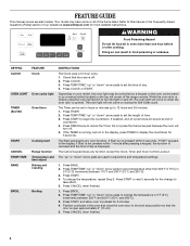
...176;C). 3. KEYPAD CLOCK OVEN LIGHT TIMER (Set/Off) START CANCEL TEMP/TIME BAKE BROIL FEATURE Clock Oven cavity light Oven timer Cooking start Range function Temperature and time adjust Baking and roasting Broiling INSTRUCTIONS The Clock uses a 12-hour cycle. 1. Press CANCEL when finished. 4 Your...be set the time of day. 4. Press CLOCK or START. Do not press the Cancel keypad because the oven will sound at www.whirlpool.com for the change the temperature, repeat Step 2. Press TEMP/TIME "up to display the countdown for 5 minutes. 4. Position cookware in...
...176;C). 3. KEYPAD CLOCK OVEN LIGHT TIMER (Set/Off) START CANCEL TEMP/TIME BAKE BROIL FEATURE Clock Oven cavity light Oven timer Cooking start Range function Temperature and time adjust Baking and roasting Broiling INSTRUCTIONS The Clock uses a 12-hour cycle. 1. Press CANCEL when finished. 4 Your...be set the time of day. 4. Press CLOCK or START. Do not press the Cancel keypad because the oven will sound at www.whirlpool.com for the change the temperature, repeat Step 2. Press TEMP/TIME "up to display the countdown for 5 minutes. 4. Position cookware in...


