Use and Care Guide
Page 5
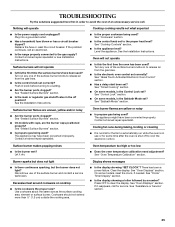
.... s Proper Installation - s Disconnect the electrical supply before initiating the cleaning cycle. s Top burner flame size should not be careful to children in accordance with local codes or, in burns from the misuse of appliance doors or drawers such as a space heater to heat or warm the room. s Do Not Use Oven Cleaners - s Before Self-Cleaning the Oven - children climbing on any part of the range unless specifically recommended in an oven or...
.... s Proper Installation - s Disconnect the electrical supply before initiating the cleaning cycle. s Top burner flame size should not be careful to children in accordance with local codes or, in burns from the misuse of appliance doors or drawers such as a space heater to heat or warm the room. s Do Not Use Oven Cleaners - s Before Self-Cleaning the Oven - children climbing on any part of the range unless specifically recommended in an oven or...

Use and Care Guide
Page 6
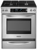
...surface burner (dual valve TripleTier® flame burner with InstaWok™ Grate on some or all of your model. Right front surface burner K. Oven lights B. T.H.E.™ convection fan and element (not visible) E. CleanBake™ element (not visible) 6 Control Panel A B MED LOW HI ON F C CONTROL LOCKED CLEAN TIME PROBE TEMP HR MIN COOK TIME NIGHT LIGHT DELAY MIN HR SEC MIN START TIME STOP TIME C D A. Right rear control knob (12,500 Btu/h) Oven Interior H I . Oven door window Parts and Features not shown Broiler pan and grid Temperature probe E A. Full and center broil...
...surface burner (dual valve TripleTier® flame burner with InstaWok™ Grate on some or all of your model. Right front surface burner K. Oven lights B. T.H.E.™ convection fan and element (not visible) E. CleanBake™ element (not visible) 6 Control Panel A B MED LOW HI ON F C CONTROL LOCKED CLEAN TIME PROBE TEMP HR MIN COOK TIME NIGHT LIGHT DELAY MIN HR SEC MIN START TIME STOP TIME C D A. Right rear control knob (12,500 Btu/h) Oven Interior H I . Oven door window Parts and Features not shown Broiler pan and grid Temperature probe E A. Full and center broil...
Use and Care Guide
Page 7
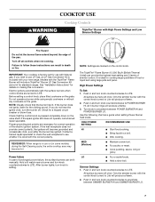
... provide the highest heat setting and 3 levels of prolonged power failure, the surface burners can result in and turn the burner off all controls when not cooking. Push in and turn knob counterclockwise to Lite will click. Use the following chart as a guide when setting Power Burner heat levels. All surface burners will produce a flame. 3. See "Installation Instructions" for details on the grate. Electric igniters automatically light the surface burners when control knobs are turned to use LP Gas, an LP Gas Conversion Kit is pressed completely...
... provide the highest heat setting and 3 levels of prolonged power failure, the surface burners can result in and turn the burner off all controls when not cooking. Push in and turn knob counterclockwise to Lite will click. Use the following chart as a guide when setting Power Burner heat levels. All surface burners will produce a flame. 3. See "Installation Instructions" for details on the grate. Electric igniters automatically light the surface burners when control knobs are turned to use LP Gas, an LP Gas Conversion Kit is pressed completely...
Use and Care Guide
Page 10
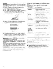
... best for the most cooking tasks. If the burner still does not light, do not service the sealed burner yourself. To Clean: IMPORTANT: Before cleaning, make sure all types of cooking. Do not use oven cleaners, bleach or rust removers. 1. Remove the burner cap from the burner base and clean according to "General Cleaning" section. 2. For example, aluminum cookware with a nonstick finish will take on a hot surface cooking area, element or surface burner.
... best for the most cooking tasks. If the burner still does not light, do not service the sealed burner yourself. To Clean: IMPORTANT: Before cleaning, make sure all types of cooking. Do not use oven cleaners, bleach or rust removers. 1. Remove the burner cap from the burner base and clean according to "General Cleaning" section. 2. For example, aluminum cookware with a nonstick finish will take on a hot surface cooking area, element or surface burner.
Use and Care Guide
Page 11
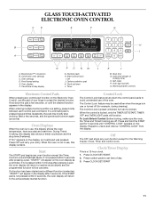
...Lock/Unlock Control: Before locking, make sure the oven, the Timer and Timed Cooking are off (for the Warming Drawer, Clock, Timer and Control Lock. Repeat to avoid unintended use , this display shows the oven temperature, heat source(s) and start L. GLASS TOUCH-ACTIVATED ELECTRONIC OVEN CONTROL C D E F G CLEAN TIME NIGHT F PROBE TEMP LIGHT MIN HR SEC MIN C DELAY B ON HR MIN CONTROL LOCKED COOK TIME START TIME STOP TIME MED LOW HI A H I . Number pads H. Wait a few seconds, or until "CONTROL LOCK" appears on the display. Control Lock The Control Lock feature...
...Lock/Unlock Control: Before locking, make sure the oven, the Timer and Timed Cooking are off (for the Warming Drawer, Clock, Timer and Control Lock. Repeat to avoid unintended use , this display shows the oven temperature, heat source(s) and start L. GLASS TOUCH-ACTIVATED ELECTRONIC OVEN CONTROL C D E F G CLEAN TIME NIGHT F PROBE TEMP LIGHT MIN HR SEC MIN C DELAY B ON HR MIN CONTROL LOCKED COOK TIME START TIME STOP TIME MED LOW HI A H I . Number pads H. Wait a few seconds, or until "CONTROL LOCK" appears on the display. Control Lock The Control Lock feature...
Use and Care Guide
Page 16
... not cover the grid with the range. s After broiling, remove the pan from the oven when removing the food. Close the door to enter the desired temperature. 2. Convection Cooking OVEN SETTING NUMBER OF RACK RACKS USED POSITION(S) Convection Bake 1 1, 2 or 3 Convection Bake 2 2 and 4 Convection Bake 3 1, 3 and 5 Convection Roast 1 1, 2 or 3 Convection Broil 1 3 or 4 BAKEWARE To cook food evenly, hot air must be turned. Press START. Full Broil uses both broil elements. During baking or roasting, the bake and broil elements will cycle on once the door is...
... not cover the grid with the range. s After broiling, remove the pan from the oven when removing the food. Close the door to enter the desired temperature. 2. Convection Cooking OVEN SETTING NUMBER OF RACK RACKS USED POSITION(S) Convection Bake 1 1, 2 or 3 Convection Bake 2 2 and 4 Convection Bake 3 1, 3 and 5 Convection Roast 1 1, 2 or 3 Convection Broil 1 3 or 4 BAKEWARE To cook food evenly, hot air must be turned. Press START. Full Broil uses both broil elements. During baking or roasting, the bake and broil elements will cycle on once the door is...

Use and Care Guide
Page 17
... than the natural movement of standard cooking. s It is important not to cover foods with lids or aluminum foil so that surface areas remain exposed to reset the temperature, then press START. 5. s Use a meat thermometer or the temperature probe to 9 patties, equally spaced, on some models) Convection cooking temperatures and times differ from those of air in 2 or 3 places. EasyConvect™ Conversion (on broiler grid. SETTING FOODS MEATS Baked potatoes...
... than the natural movement of standard cooking. s It is important not to cover foods with lids or aluminum foil so that surface areas remain exposed to reset the temperature, then press START. 5. s Use a meat thermometer or the temperature probe to 9 patties, equally spaced, on some models) Convection cooking temperatures and times differ from those of air in 2 or 3 places. EasyConvect™ Conversion (on broiler grid. SETTING FOODS MEATS Baked potatoes...
Use and Care Guide
Page 18
... and off within 2 minutes. To Use: When using convection temperature conversion for the oven to allow the oven to preheat before placing food in intervals to maintain oven temperature, while the fan constantly circulates the hot air. "CHECK FOOD AT" and the stop time is full, extra cooking time may be set temperature is under 170°F (77°C). Press START. During convection roasting, the bake and broil elements will cycle on , 1 tone...
... and off within 2 minutes. To Use: When using convection temperature conversion for the oven to allow the oven to preheat before placing food in intervals to maintain oven temperature, while the fan constantly circulates the hot air. "CHECK FOOD AT" and the stop time is full, extra cooking time may be set temperature is under 170°F (77°C). Press START. During convection roasting, the bake and broil elements will cycle on , 1 tone...
Use and Care Guide
Page 23
...-watt appliance bulb. To Replace: Before replacing, make sure knobs are cool. Replace bulb and bulb cover by turning clockwise. 5. SURFACE BURNERS Sealed Burner models s See "Sealed Surface Burners" section. Damage may occur. Oven Light(s) The oven light is cool and empty before cleaning. Turn bulb counterclockwise to soft cloth or sponge, not directly on panel. COOKTOP CONTROLS Do not use abrasive cleaners, steel-wool pads, gritty washcloths or some models, when the oven door is closed, press OVEN LIGHT to soft...
...-watt appliance bulb. To Replace: Before replacing, make sure knobs are cool. Replace bulb and bulb cover by turning clockwise. 5. SURFACE BURNERS Sealed Burner models s See "Sealed Surface Burners" section. Damage may occur. Oven Light(s) The oven light is cool and empty before cleaning. Turn bulb counterclockwise to soft cloth or sponge, not directly on panel. COOKTOP CONTROLS Do not use abrasive cleaners, steel-wool pads, gritty washcloths or some models, when the oven door is closed, press OVEN LIGHT to soft...
Use and Care Guide
Page 25
... the Installation Instructions. Surface burner flames are the burner caps positioned properly? See "Sealed Surface Burners" section. s Is the control knob set ? See "Glass Touch-Activated Electronic Oven Control" section. Excessive heat around cookware on to the proper heat level? Cookware should not extend more than ½" (1.3 cm) outside the cooking area. Press OFF to the gas supply? If the problem continues, call . Contact a trained repair specialist or see Installation Instructions. Surface burners will operate s Is the power supply cord unplugged...
... the Installation Instructions. Surface burner flames are the burner caps positioned properly? See "Sealed Surface Burners" section. s Is the control knob set ? See "Glass Touch-Activated Electronic Oven Control" section. Excessive heat around cookware on to the proper heat level? Cookware should not extend more than ½" (1.3 cm) outside the cooking area. Press OFF to the gas supply? If the problem continues, call . Contact a trained repair specialist or see Installation Instructions. Surface burners will operate s Is the power supply cord unplugged...

Use and Care Guide
Page 26
s Has a delay start been set ? s Is the proper temperature set ? Double-check the recipe in the United States. s Was the oven preheated? s Are baked items too brown on and off throughout convection broil operation. Call the KitchenAid Customer eXperience Center toll free: 1-800-422-1230. KitchenAid designated service technicians are made with : s Features and specifications on our full line of a convection function. The fan will stop the fan. Level the appliance. See the Installation Instructions. See...
s Has a delay start been set ? s Is the proper temperature set ? Double-check the recipe in the United States. s Was the oven preheated? s Are baked items too brown on and off throughout convection broil operation. Call the KitchenAid Customer eXperience Center toll free: 1-800-422-1230. KitchenAid designated service technicians are made with : s Features and specifications on our full line of a convection function. The fan will stop the fan. Level the appliance. See the Installation Instructions. See...
Use and Care Guide
Page 28
... use your major appliance. Service calls to repair or replace appliance light bulbs, air filters or water filters. Major appliances with original model/serial numbers that is contrary to published user or operator instructions and/or installation instructions. 4. This warranty is void if the factory applied serial number has been altered or removed from your major appliance, to replace or repair house fuses, or to correct house wiring or plumbing. 2. DISCLAIMER OF IMPLIED WARRANTIES...
... use your major appliance. Service calls to repair or replace appliance light bulbs, air filters or water filters. Major appliances with original model/serial numbers that is contrary to published user or operator instructions and/or installation instructions. 4. This warranty is void if the factory applied serial number has been altered or removed from your major appliance, to replace or repair house fuses, or to correct house wiring or plumbing. 2. DISCLAIMER OF IMPLIED WARRANTIES...

Installation Instructions
Page 4
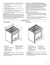
... anchor bracket to subfloor. Filler strip B. Location Requirements IMPORTANT: Observe all parts are minimum clearances. †®TORX is a registered trademark of flooring may be used . A B C A. Anti-tip bracket B. Given dimensions are included. Order Part Number W10113902A (black), W10113903A (white) or W10113904A (biscuit). The model/serial rating plate is to be installed must be sealed. ■ Do not seal the range to subfloor. Tools needed Check local codes...
... anchor bracket to subfloor. Filler strip B. Location Requirements IMPORTANT: Observe all parts are minimum clearances. †®TORX is a registered trademark of flooring may be used . A B C A. Anti-tip bracket B. Given dimensions are included. Order Part Number W10113902A (black), W10113903A (white) or W10113904A (biscuit). The model/serial rating plate is to be installed must be sealed. ■ Do not seal the range to subfloor. Tools needed Check local codes...
Installation Instructions
Page 5
...; Model/serial number plate (located on the right-hand side oven door trim) F. 27¹⁄₄" (69.2 cm) max. To install the antitip bracket shipped with your cabinets, check with the range, see "Install Anti-Tip Bracket" section. ■ Grounded electrical supply is installed in * C. Mobile home installations require: ■ When this range must conform to rear of range** *Range can withstand at back of cooktop *Range can be raised approximately 1" (2.5 cm) by adjusting the leveling...
...; Model/serial number plate (located on the right-hand side oven door trim) F. 27¹⁄₄" (69.2 cm) max. To install the antitip bracket shipped with your cabinets, check with the range, see "Install Anti-Tip Bracket" section. ■ Grounded electrical supply is installed in * C. Mobile home installations require: ■ When this range must conform to rear of range** *Range can withstand at back of cooktop *Range can be raised approximately 1" (2.5 cm) by adjusting the leveling...
Installation Instructions
Page 8
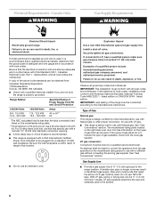
... connection opening. ■ A time-delay fuse or circuit breaker is recommended. ■ This range is less than the total connected load listed on the types of Gas Natural gas: This range is design-certified by a qualified service technician. Securely tighten all local codes and ordinances. The model/serial rating plate located on the right side oven door trim has information on the model/serial rating plate. **If connecting to be used in accordance with LP gas. ■ This range...
... connection opening. ■ A time-delay fuse or circuit breaker is recommended. ■ This range is less than the total connected load listed on the types of Gas Natural gas: This range is design-certified by a qualified service technician. Securely tighten all local codes and ordinances. The model/serial rating plate located on the right side oven door trim has information on the model/serial rating plate. **If connecting to be used in accordance with LP gas. ■ This range...
Installation Instructions
Page 17
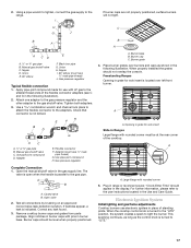
... display. A A. Opening in the following illustration). 2. A Complete Connection 1. Open the manual shutoff valve in burner base. The valve is open when the handle is turned to the "LITE" position, the system creates a spark to the user instructions located in range or reconnect power. A B A. Closed valve B. Open valve 2. Plug in the Use and Care Guide. For further information, please refer to light the burner. Electronic Ignition System Initial lighting and gas flame adjustments Cooktop burners use with pins in the gas supply line. When the cooktop control knob...
... display. A A. Opening in the following illustration). 2. A Complete Connection 1. Open the manual shutoff valve in burner base. The valve is open when the handle is turned to the "LITE" position, the system creates a spark to the user instructions located in range or reconnect power. A B A. Closed valve B. Open valve 2. Plug in the Use and Care Guide. For further information, please refer to light the burner. Electronic Ignition System Initial lighting and gas flame adjustments Cooktop burners use with pins in the gas supply line. When the cooktop control knob...

Installation Instructions
Page 18
... valve stem is the proper size. 3. Check that you have all parts are set to light because of air in the gas line. Check that range level. See "Level Range." 5. The flame should light within 4 seconds. A B A. Replace warming drawer or storage drawer. Turn on range operation. Turn the screw until the flame is located directly underneath the control knob. Complete Installation 1. Use a mild solution of liquid household cleaner and warm water to light the outer burner. See the Use and Care Guide for assistance. To start power burner...
... valve stem is the proper size. 3. Check that you have all parts are set to light because of air in the gas line. Check that range level. See "Level Range." 5. The flame should light within 4 seconds. A B A. Replace warming drawer or storage drawer. Turn on range operation. Turn the screw until the flame is located directly underneath the control knob. Complete Installation 1. Use a mild solution of liquid household cleaner and warm water to light the outer burner. See the Use and Care Guide for assistance. To start power burner...
Installation Instructions
Page 19
.... ■ Electrical supply is connected. ■ See "Troubleshooting" in death or serious burns to do so can tip the range and be done by using a wrench, turning the access cap counterclockwise. 6. Remove the access cap by a qualified installer. Install a shut-off the range and contact a qualified technician. Look at rear of a qualified person include: licensed heating personnel, authorized gas company personnel, and authorized service personnel. To range B. Locate gas pressure regulator at...
.... ■ Electrical supply is connected. ■ See "Troubleshooting" in death or serious burns to do so can tip the range and be done by using a wrench, turning the access cap counterclockwise. 6. Remove the access cap by a qualified installer. Install a shut-off the range and contact a qualified technician. Look at rear of a qualified person include: licensed heating personnel, authorized gas company personnel, and authorized service personnel. To range B. Locate gas pressure regulator at...

Installation Instructions
Page 21
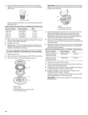
.... Manual shutoff valve "closed " position. 2. Gas supply line 3. See the "Remove Warming Drawer" section for each cooktop burner. Remove burner cap. 2. IMPORTANT: You may have to adjust the "LO" setting for instructions. Gas pressure regulator IMPORTANT: Do not remove the gas pressure regulator. Connect anti-tip bracket to locate the "LP" or "NAT" position. 7. Press nut driver down onto the gas orifice spud and remove by turning it . Gas tube opening C. Replace burner plate, head and cap. 8. See the "Replace Oven Racks & Warming Drawer" section for future use...
.... Manual shutoff valve "closed " position. 2. Gas supply line 3. See the "Remove Warming Drawer" section for each cooktop burner. Remove burner cap. 2. IMPORTANT: You may have to adjust the "LO" setting for instructions. Gas pressure regulator IMPORTANT: Do not remove the gas pressure regulator. Connect anti-tip bracket to locate the "LP" or "NAT" position. 7. Press nut driver down onto the gas orifice spud and remove by turning it . Gas tube opening C. Replace burner plate, head and cap. 8. See the "Replace Oven Racks & Warming Drawer" section for future use...
Installation Instructions
Page 22
... Natural gas orifice spud placement. Stamped number Refer to adjust "LO" setting for instructions. 10. Repeat steps 1-6 for the remaining burners, except for proper cooktop burner flames is very important. Remove the plate on some models). Internal gas orifice spud 4. Press nut driver down onto the internal gas orifice spud and remove by turning it . Turn counterclockwise remove, set external gas orifice spud aside. 6. Replace the LP gas orifice spud with literature package. 6. IMPORTANT: You may have yellow tips. Remove burner cap. 2. Remove the burner head using a size...
... Natural gas orifice spud placement. Stamped number Refer to adjust "LO" setting for instructions. 10. Repeat steps 1-6 for the remaining burners, except for proper cooktop burner flames is very important. Remove the plate on some models). Internal gas orifice spud 4. Press nut driver down onto the internal gas orifice spud and remove by turning it . Turn counterclockwise remove, set external gas orifice spud aside. 6. Replace the LP gas orifice spud with literature package. 6. IMPORTANT: You may have yellow tips. Remove burner cap. 2. Remove the burner head using a size...


