User Manual
Page 2
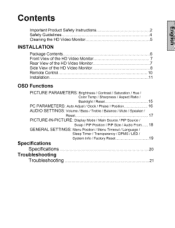
...Front View of the HD Video Monitor 7 Rear View of the HD Video Monitor 7 Side View of the HD Video Monitor 8 Remote Control 10 Installation 11 OSD Functions PICTURE PARAMETERS: Brightness / Contrast / Saturation / Hue / Color Temp / Sharpness / Aspect Ratio / Backlight / Reset 15 PC PARAMETERS: Auto Adjust / Clock / Phase / Position 16 AUDIO SETTINGS: Volume / Bass / Treble / Balance / Mute / Speaker/ Reset 17 PICTURE-IN-PICTURE: Display Mode / Main Source / PIP Source / GENERAL SETTINGS: Swap / PIP Position / PIP Size / Audio From ..... 18 Menu Position...
...Front View of the HD Video Monitor 7 Rear View of the HD Video Monitor 7 Side View of the HD Video Monitor 8 Remote Control 10 Installation 11 OSD Functions PICTURE PARAMETERS: Brightness / Contrast / Saturation / Hue / Color Temp / Sharpness / Aspect Ratio / Backlight / Reset 15 PC PARAMETERS: Auto Adjust / Clock / Phase / Position 16 AUDIO SETTINGS: Volume / Bass / Treble / Balance / Mute / Speaker/ Reset 17 PICTURE-IN-PICTURE: Display Mode / Main Source / PIP Source / GENERAL SETTINGS: Swap / PIP Position / PIP Size / Audio From ..... 18 Menu Position...

User Manual
Page 3
...flash with arrowhead symbol, inside an equiiaterat triangle, is intended to alert the user to the presence of u ninsuiated "dangerous voltage" within the product's enclosure that may be of sufficient magnitude to constitute a risk of electrical shack to persons, SA 1966 iNSTRUCTiONS... : The exeiaraation point inside an equilateral triangle is intended to ale_ the user to the presence af important operating end maintenance ( servicing ) instructions in the literature accompanying the appliance.
...flash with arrowhead symbol, inside an equiiaterat triangle, is intended to alert the user to the presence of u ninsuiated "dangerous voltage" within the product's enclosure that may be of sufficient magnitude to constitute a risk of electrical shack to persons, SA 1966 iNSTRUCTiONS... : The exeiaraation point inside an equilateral triangle is intended to ale_ the user to the presence af important operating end maintenance ( servicing ) instructions in the literature accompanying the appliance.
User Manual
Page 4
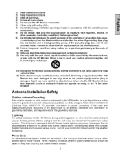
... obey all the safety and operating instructions before you touch them . The HD Monitor shall be placed on the HD Monitor, audio/video cables, or power cord. • If the HD Monitor emits smoke, abnormal noise, or a strange odor, immediately turn it . • Place the HD Monitor in a well-ventilated area; Your warranty does not cover repairs or attempted repairs by anyone not authorized by...
... obey all the safety and operating instructions before you touch them . The HD Monitor shall be placed on the HD Monitor, audio/video cables, or power cord. • If the HD Monitor emits smoke, abnormal noise, or a strange odor, immediately turn it . • Place the HD Monitor in a well-ventilated area; Your warranty does not cover repairs or attempted repairs by anyone not authorized by...
User Manual
Page 5
... grounding electrode. When installing an outside antenna or cable system is connected to the HD Monitor, be located in accordance with the HD Monitor. If the provided plug does not fit into the HD Monitor, it does not operate normally, or the TV has been dropped. Servicing is not being walked on proper grounding of the mast and supporting structure, grounding of...
... grounding electrode. When installing an outside antenna or cable system is connected to the HD Monitor, be located in accordance with the HD Monitor. If the provided plug does not fit into the HD Monitor, it does not operate normally, or the TV has been dropped. Servicing is not being walked on proper grounding of the mast and supporting structure, grounding of...
User Manual
Page 6
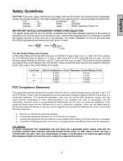
... LCD Monitor and receiver. • Connect the equipment into an outlet on a desk or table, type SVT or SJT cord sets may be selected according to operate this device. 4 This equipment generates, uses, and can be used , use a grounded power supply cord and the provided shielded video interface cable with bonded ferrite cores. If this HD Monitor is necessary to provide reasonable protection against harmful interference in a residential installation...
... LCD Monitor and receiver. • Connect the equipment into an outlet on a desk or table, type SVT or SJT cord sets may be selected according to operate this device. 4 This equipment generates, uses, and can be used , use a grounded power supply cord and the provided shielded video interface cable with bonded ferrite cores. If this HD Monitor is necessary to provide reasonable protection against harmful interference in a residential installation...
User Manual
Page 7
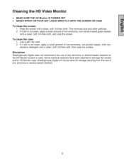
...or alcohol-based cleaners on the HD Monitor screen or case. Westinghouse Digital will not be liable for damage resulting from the use of non-ammonia, non-alcohol based glass cleaner onto a clean, soft, lint-free cloth, and wipe the screen. This removes dust and...based, mild non- Wipe the screen with a clean, soft, lint-free cloth. If it still is not clean, apply a small amount of any ammonia or alcohol-based cleaners. Some chemical cleaners have been reported to damage the screen and/or HD Monitor case. Cleaning the HD Video Monitor • MAKE SURE THE HD Monitor IS TURNED...
...or alcohol-based cleaners on the HD Monitor screen or case. Westinghouse Digital will not be liable for damage resulting from the use of non-ammonia, non-alcohol based glass cleaner onto a clean, soft, lint-free cloth, and wipe the screen. This removes dust and...based, mild non- Wipe the screen with a clean, soft, lint-free cloth. If it still is not clean, apply a small amount of any ammonia or alcohol-based cleaners. Some chemical cleaners have been reported to damage the screen and/or HD Monitor case. Cleaning the HD Video Monitor • MAKE SURE THE HD Monitor IS TURNED...
User Manual
Page 8
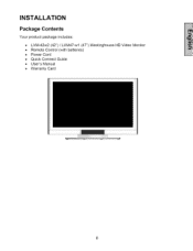
INSTALLATION Package Contents Your product package includes: • LVM-42w2 (42") / LVM47-w1 (47") Westinghouse • Remote Control (with batteries) • Power Cord • Quick Connect Guide • User's Manual • Warranty Card HD Video Monitor
INSTALLATION Package Contents Your product package includes: • LVM-42w2 (42") / LVM47-w1 (47") Westinghouse • Remote Control (with batteries) • Power Cord • Quick Connect Guide • User's Manual • Warranty Card HD Video Monitor
User Manual
Page 9
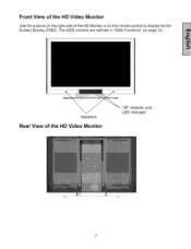
The OSD controls are defined in "OSD Functions" on page 12. Speakers Rear View of the HD Monitor or on the remote control to display the On Screen Display (OSD). Front View of the HD Video Monitor Use the buttons on the right side of the liD Video Monitor "IR" receiver and LED indicator
The OSD controls are defined in "OSD Functions" on page 12. Speakers Rear View of the HD Monitor or on the remote control to display the On Screen Display (OSD). Front View of the HD Video Monitor Use the buttons on the right side of the liD Video Monitor "IR" receiver and LED indicator
User Manual
Page 11
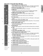
... player or video game system. 7. HD Digital cable/satellite 1 receiver. DVl2 Audio Input (Right / Left) Connect an external DVI audio source to this output to a computer or other device with a VGA output. 11. Media Center PC. DVD or other device with component output to an external video device such as DVD or video game system with a DVI output. 2. Audio Output (Right / Left) Connect this jack. 2 3. 5 14 16 Side View of the HD Video Monitor 1. HDMI Input Connect to these jacks. 15. This connection 8 supports either S-Video...
... player or video game system. 7. HD Digital cable/satellite 1 receiver. DVl2 Audio Input (Right / Left) Connect an external DVI audio source to this output to a computer or other device with a VGA output. 11. Media Center PC. DVD or other device with component output to an external video device such as DVD or video game system with a DVI output. 2. Audio Output (Right / Left) Connect this jack. 2 3. 5 14 16 Side View of the HD Video Monitor 1. HDMI Input Connect to these jacks. 15. This connection 8 supports either S-Video...
User Manual
Page 12
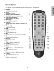
POWER: Switch the power On/Off 2. SCALING Select Video Display format "STANDARD" or "FILL" 7. DVI Select DVll / DVl2 / HDMI source input 18. VGA 1 Select VGA source input 11. V/A/41/_ 4 OSD MENU control 8. Remote Control The Remote Control will transmit to the HD Monitor up to 10 feet away. 1. INPUT Select input source 3. MUTE Turn the Sound On/Off 7 8 10.1NFO Display the source and channel information 11.PIP Display sub-picture On/Off t0 12. Source selection Up/Down 15.YPbPr...
POWER: Switch the power On/Off 2. SCALING Select Video Display format "STANDARD" or "FILL" 7. DVI Select DVll / DVl2 / HDMI source input 18. VGA 1 Select VGA source input 11. V/A/41/_ 4 OSD MENU control 8. Remote Control The Remote Control will transmit to the HD Monitor up to 10 feet away. 1. INPUT Select input source 3. MUTE Turn the Sound On/Off 7 8 10.1NFO Display the source and channel information 11.PIP Display sub-picture On/Off t0 12. Source selection Up/Down 15.YPbPr...
User Manual
Page 13
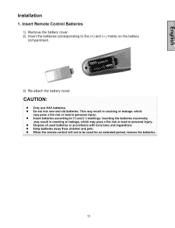
... or leakage, which may pose a fire risk or lead to personal injury, • Dispose of used for an extended period, remove the batteries, 11 Installation 1, Insert Remote Control Batteries 1) Remove the battery cover. 2) Insert the batteries corresponding compartment. to be used batteries in accordance with local laws and regulations, • Keep batteries away from children and pets...
... or leakage, which may pose a fire risk or lead to personal injury, • Dispose of used for an extended period, remove the batteries, 11 Installation 1, Insert Remote Control Batteries 1) Remove the battery cover. 2) Insert the batteries corresponding compartment. to be used batteries in accordance with local laws and regulations, • Keep batteries away from children and pets...
User Manual
Page 14
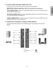
Connect AV, Component, S-Video to Video Devices Connect Audio/Video cables from compatible devices to the AUDIO IN port on the HD Monitor. 3. ii_i_i_;/_ ¸ iiiiiiii/ 12 AUDIO CONNECTION" Connect a stereo mini cable from your PC DVI OUT port to the HD Monitor VGA IN port. VGA CONNECTION: Connect an analog VGA cable from the PC's AUDIO OUT port to the back panel of the HD Monitor. DVII/DVI2 CONNECTION: Connect a Digital DVI cable from a PC Connect one of the HD Monitor IMPORTANT: Before...
Connect AV, Component, S-Video to Video Devices Connect Audio/Video cables from compatible devices to the AUDIO IN port on the HD Monitor. 3. ii_i_i_;/_ ¸ iiiiiiii/ 12 AUDIO CONNECTION" Connect a stereo mini cable from your PC DVI OUT port to the HD Monitor VGA IN port. VGA CONNECTION: Connect an analog VGA cable from the PC's AUDIO OUT port to the back panel of the HD Monitor. DVII/DVI2 CONNECTION: Connect a Digital DVI cable from a PC Connect one of the HD Monitor IMPORTANT: Before...
User Manual
Page 15
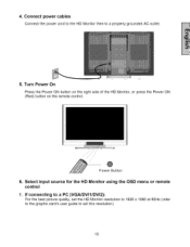
Select input source for the HD Monitor using the OSD menu or remote control 7. 4. If connecting to a PC (VGA/DVI1/DVI2): For the best picture quality, set the HD Monitor resolution to 1920 x 1080 at 60Hz (refer to the graphic card's user guide to a properly grounded AC outlet. 5. Turn Power On Press the Power ON button on the right side of the HD Monitor, or press the Power ON (Red) button on the remote control. Connect power cables Connect the power cord to the HD Monitor then to set this resolution). 13 Power Button 6.
Select input source for the HD Monitor using the OSD menu or remote control 7. 4. If connecting to a PC (VGA/DVI1/DVI2): For the best picture quality, set the HD Monitor resolution to 1920 x 1080 at 60Hz (refer to the graphic card's user guide to a properly grounded AC outlet. 5. Turn Power On Press the Power ON button on the right side of the HD Monitor, or press the Power ON (Red) button on the remote control. Connect power cables Connect the power cord to the HD Monitor then to set this resolution). 13 Power Button 6.
User Manual
Page 16
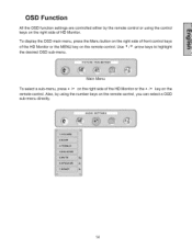
OSD Function All the OSD function settings are controlled either by using the control keys on the remote control. To display the OSD main menu, press the Menu button on the right side of front control keys of the HD Monitor or the • /v key on the remote control. Also, by the remote control or using the number keys on the remote control, you can select a OSD sub-menu directly. 14 Main Menu To select a sub-menu, press • /v on the right side of the HD Monitor or the MENU key on the right side of HD Monitor. Use _ / _ arrow keys to highlight the desired OSD sub-menu.
OSD Function All the OSD function settings are controlled either by using the control keys on the remote control. To display the OSD main menu, press the Menu button on the right side of front control keys of the HD Monitor or the • /v key on the remote control. Also, by the remote control or using the number keys on the remote control, you can select a OSD sub-menu directly. 14 Main Menu To select a sub-menu, press • /v on the right side of the HD Monitor or the MENU key on the right side of HD Monitor. Use _ / _ arrow keys to highlight the desired OSD sub-menu.
User Manual
Page 17
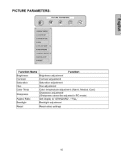
Brightness Brightness adjustment Contrast Contrast adjustment Saturation Saturation adjustment Hue Hue adjustment Color Temp Color temperature adjustment (Warm, Neutral, Cool) Sharpness Sharpness adjustment (Sharpness cannot be adjusted in PC mode) Aspect Ratio Set display to "STANDARD" / "FILL" Backlight Backlight adjustment Reset Reset video settings 15 PICTURE PARAMETERS: Function Name Function i...
Brightness Brightness adjustment Contrast Contrast adjustment Saturation Saturation adjustment Hue Hue adjustment Color Temp Color temperature adjustment (Warm, Neutral, Cool) Sharpness Sharpness adjustment (Sharpness cannot be adjusted in PC mode) Aspect Ratio Set display to "STANDARD" / "FILL" Backlight Backlight adjustment Reset Reset video settings 15 PICTURE PARAMETERS: Function Name Function i...
User Manual
Page 19
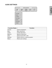
AUDIO SETTINGS: Function Volume Bass Treble Balance Mute Speaker Reset Name I Function Volume adjustment Bass adjustment Treble adjustment Balance adjustment Select Audio OFF or ON Select internal or external speaker Reset audio settings 17
AUDIO SETTINGS: Function Volume Bass Treble Balance Mute Speaker Reset Name I Function Volume adjustment Bass adjustment Treble adjustment Balance adjustment Select Audio OFF or ON Select internal or external speaker Reset audio settings 17
User Manual
Page 21
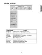
GENERAL SETTINGS: Function Name Menu Position Menu Timeout Language Sleep Timer Transparency DPMS LED Auto Source System Info Factory Reset Function OSD horizontal/vertical position adjustment Set the time to turn off the OSD automatically OSD language selection Set sleep timer to turn off the power automatically Set OSD transparency level Select DPMS On/Off Turn the LED ON or OFF Select auto source function on/off Display Input source, type and signal Restore factory default settings 19
GENERAL SETTINGS: Function Name Menu Position Menu Timeout Language Sleep Timer Transparency DPMS LED Auto Source System Info Factory Reset Function OSD horizontal/vertical position adjustment Set the time to turn off the OSD automatically OSD language selection Set sleep timer to turn off the power automatically Set OSD transparency level Select DPMS On/Off Turn the LED ON or OFF Select auto source function on/off Display Input source, type and signal Restore factory default settings 19
User Manual
Page 22
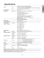
Specifications Panel Viewing Angles Input Signal Output Signal HDTV Compatibility PC Compatible (VGA, DVI1, & DVI2) Speaker Output Power Operating Conditions Storage Conditions Dimensions Weight Regulations Type Color Video/Audio Supported Voltage Temperature Humidity Altitude Temperature Humidity Altitude Physical Net / Gross LVM-42w2 (42") (42.02" viewable diagonal area) LVM-47w1 (47") (47.00" viewable diagonal area) TFT (Thin Film Transistor), Active Matrix WXGA LCD, 1920x1080 Anti-reflective coating + Anti-glare coating vertical stripe 176 ° (H)/176 ° (V) RGB...
Specifications Panel Viewing Angles Input Signal Output Signal HDTV Compatibility PC Compatible (VGA, DVI1, & DVI2) Speaker Output Power Operating Conditions Storage Conditions Dimensions Weight Regulations Type Color Video/Audio Supported Voltage Temperature Humidity Altitude Temperature Humidity Altitude Physical Net / Gross LVM-42w2 (42") (42.02" viewable diagonal area) LVM-47w1 (47") (47.00" viewable diagonal area) TFT (Thin Film Transistor), Active Matrix WXGA LCD, 1920x1080 Anti-reflective coating + Anti-glare coating vertical stripe 176 ° (H)/176 ° (V) RGB...
User Manual
Page 23
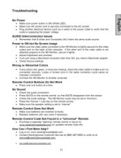
... the remote control. • Make sure the speaker setting is set to "internal". Troubleshooting No Power • Make sure power button is ON (White LED). • Make sure AC power cord is securely connected to the AC socket. • Plug another computer. Wrong or Abnormal Colors • If any colors (red, green, or blue) are missing, check the video cable to verify that the outlet is supplying the proper voltage. The HD Monitor audio...
... the remote control. • Make sure the speaker setting is set to "internal". Troubleshooting No Power • Make sure power button is ON (White LED). • Make sure AC power cord is securely connected to the AC socket. • Plug another computer. Wrong or Abnormal Colors • If any colors (red, green, or blue) are missing, check the video cable to verify that the outlet is supplying the proper voltage. The HD Monitor audio...
User Manual
Page 25
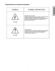
Explanations of required symbols : SYMBOL DEFINITION SA 1965 DANGEROUS VOLTAGE : The |ightning flash with arrowhead symbol, inside an equi|ateral triangle, is Intended to a_ert the user to the presence of uninsulated "dangerous voltage" with{n the product's enc|osure that may be of sufficient magnitude to constitute a risk of electr|caL shock to persons, SA 1966 INSTRUCT_ONS : The exc|amation point inside an equilateral trieng|e _sintended to atert the user to the presence of important operating and maintenance ( ser¢|c|ng ) instructions in the I|terature accompanying the appliance
Explanations of required symbols : SYMBOL DEFINITION SA 1965 DANGEROUS VOLTAGE : The |ightning flash with arrowhead symbol, inside an equi|ateral triangle, is Intended to a_ert the user to the presence of uninsulated "dangerous voltage" with{n the product's enc|osure that may be of sufficient magnitude to constitute a risk of electr|caL shock to persons, SA 1966 INSTRUCT_ONS : The exc|amation point inside an equilateral trieng|e _sintended to atert the user to the presence of important operating and maintenance ( ser¢|c|ng ) instructions in the I|terature accompanying the appliance


