
English Manual
Page 2
... injury or property damage sustained by or through the use only. Table of Contents Important Precautions 2 Before You Begin 3 Assembly 4 Cable Diagrams 23 Adjustment 25 Trouble-shooting and Maintenance 26 Weight Resistance Chart 27 Ordering Replacement Parts Back Cover Full 90-day Warranty Back Cover...all precautions. 7. Remove the PART LIST/EXPLODED DRAWING and the PART IDENTIFICATION CHART before using the home gym. 1. Make sure the cables remain on a foot plate when performing an exercise that all users of the home gym are adequately informed of the pulleys. 12. ...
... injury or property damage sustained by or through the use only. Table of Contents Important Precautions 2 Before You Begin 3 Assembly 4 Cable Diagrams 23 Adjustment 25 Trouble-shooting and Maintenance 26 Weight Resistance Chart 27 Ordering Replacement Parts Back Cover Full 90-day Warranty Back Cover...all precautions. 7. Remove the PART LIST/EXPLODED DRAWING and the PART IDENTIFICATION CHART before using the home gym. 1. Make sure the cables remain on a foot plate when performing an exercise that all users of the home gym are adequately informed of the pulleys. 12. ...
English Manual
Page 4
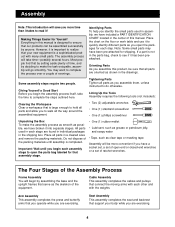
... itself, take time-possibly several hours. Do not dispose of the packing materials until you begin by setting aside plenty of the equipment. Cable Assembly This assembly completes the cables and pulleys that your body while you assemble them, unless instructed to open -end or closed-end wrenches or a set of this...
... itself, take time-possibly several hours. Do not dispose of the packing materials until you begin by setting aside plenty of the equipment. Cable Assembly This assembly completes the cables and pulleys that your body while you assemble them, unless instructed to open -end or closed-end wrenches or a set of this...
English Manual
Page 9
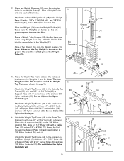
... one 3/8" x 2 3/4" Bolt (46), a Support Plate with 4" center holes (94), and two 3/8" Nylon Locknuts (50). Attach the Weight Top Frame (66) to the Weight Base (5) with a Cable Trap (25) onto a 3/8" x 4" Bolt (78). Slide a Weight Guide 15 (15) into each of the Long Weight Tube (70). Attach the indicated Weight Guide (15) to...
... one 3/8" x 2 3/4" Bolt (46), a Support Plate with 4" center holes (94), and two 3/8" Nylon Locknuts (50). Attach the Weight Top Frame (66) to the Weight Base (5) with a Cable Trap (25) onto a 3/8" x 4" Bolt (78). Slide a Weight Guide 15 (15) into each of the Long Weight Tube (70). Attach the indicated Weight Guide (15) to...
English Manual
Page 11
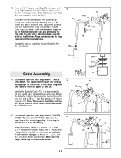
... Arm (10) with a 3/8" x 1" Bolt (84) and two 3/8" Nylon Jamnuts (63). Remove one "V"-Pulley (27) from the bag. Lubricate the indicated axle on the Cable and the two Nylon Jamnuts must be mounted underneath the welded bracket. 20. Secure the Butterfly Arm with soapy water. Note: The loop on the...with two Retainer Rings (31) and a 1" Round Outer Cap (38). Slide a Butterfly Foam Pad (29) onto the lower end of the Pro Pulley. Make sure the Large Cable Trap is approximately 52" long and it onto the axle. Note: Place the Retainer Rings on each end of the inverted Outer Cap...
... Arm (10) with a 3/8" x 1" Bolt (84) and two 3/8" Nylon Jamnuts (63). Remove one "V"-Pulley (27) from the bag. Lubricate the indicated axle on the Cable and the two Nylon Jamnuts must be mounted underneath the welded bracket. 20. Secure the Butterfly Arm with soapy water. Note: The loop on the...with two Retainer Rings (31) and a 1" Round Outer Cap (38). Slide a Butterfly Foam Pad (29) onto the lower end of the Pro Pulley. Make sure the Large Cable Trap is approximately 52" long and it onto the axle. Note: Place the Retainer Rings on each end of the inverted Outer Cap...
English Manual
Page 12
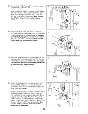
... the Pulley, so that the slots in the direction shown. ed underneath the welded bracket. 11 1 84 Bracket 63 73 24. Make sure the Large Cable Trap is approximately 224" 24 long, and it has a ball on one end and a threaded shaft on the other. Attach the Butterfly... Pulley Bracket is between the Pulley and the welded pin on the 23 Right Butterfly Arm (11) with the ball. 59 48 Wrap the Ab Cable (74) around a 3 1/2" Pulley (24) in the direction shown. You will start by attaching the end of the Butterfly Upright (1) with a 3/8" x 1 3/4" Bolt (57) and a 3/8" Nylon Locknut...
... the Pulley, so that the slots in the direction shown. ed underneath the welded bracket. 11 1 84 Bracket 63 73 24. Make sure the Large Cable Trap is approximately 224" 24 long, and it has a ball on one end and a threaded shaft on the other. Attach the Butterfly... Pulley Bracket is between the Pulley and the welded pin on the 23 Right Butterfly Arm (11) with the ball. 59 48 Wrap the Ab Cable (74) around a 3 1/2" Pulley (24) in the direction shown. You will start by attaching the end of the Butterfly Upright (1) with a 3/8" x 1 3/4" Bolt (57) and a 3/8" Nylon Locknut...
English Manual
Page 13
...24 74 74 54 24 25 4 50 13 Remove both 3 1/2" Pulleys (24) from the pre-assembled Adjustable Pulley Plates (23). Attach the Pulley and a Cable Trap (25) to the Small Pulley Bracket (22) with a 3/8" x 1 3/4" Bolt (57) and a 3/8" Nylon Locknut (50). Make sure the... Cable Trap and the Pulley Plates are oriented as shown. 27. Wrap the Ab Cable (74) around a 3 1/2" Pulley (24) in the two Adjustable Pulley Plates (23) with a 3/8" x 2" Bolt (54) and a 3/8" Nylon Locknut (50). ...
...24 74 74 54 24 25 4 50 13 Remove both 3 1/2" Pulleys (24) from the pre-assembled Adjustable Pulley Plates (23). Attach the Pulley and a Cable Trap (25) to the Small Pulley Bracket (22) with a 3/8" x 1 3/4" Bolt (57) and a 3/8" Nylon Locknut (50). Make sure the... Cable Trap and the Pulley Plates are oriented as shown. 27. Wrap the Ab Cable (74) around a 3 1/2" Pulley (24) in the two Adjustable Pulley Plates (23) with a 3/8" x 2" Bolt (54) and a 3/8" Nylon Locknut (50). ...
English Manual
Page 14
... 30. Attach the "U"-Bracket (97) to a "U"Bracket (97) with a 3/8" x 1 3/4" Bolt (57) and a 3/8" Nylon Locknut (50). Wrap the Ab Cable (74) around a 4 1/2" Pulley (82) in the Short Weight Tube (17) with a 3/8" Nylon Jamnut (63). Note: Do not completely tighten the Nylon Locknut;... 1/4" 30 Nylon Locknut (68). Secure the Pulley with a 5/16" x 1 3/4" Bolt (96) and a 5/16" Nylon Locknut (64). 28. Wrap the Ab Cable (74) around a 3 1/2" Pulley (24) in the direction shown. 4 Note: For clarity, this and the following drawings show some parts removed. 29. Slide the Pulley...
... 30. Attach the "U"-Bracket (97) to a "U"Bracket (97) with a 3/8" x 1 3/4" Bolt (57) and a 3/8" Nylon Locknut (50). Wrap the Ab Cable (74) around a 4 1/2" Pulley (82) in the Short Weight Tube (17) with a 3/8" Nylon Jamnut (63). Note: Do not completely tighten the Nylon Locknut;... 1/4" 30 Nylon Locknut (68). Secure the Pulley with a 5/16" x 1 3/4" Bolt (96) and a 5/16" Nylon Locknut (64). 28. Wrap the Ab Cable (74) around a 3 1/2" Pulley (24) in the direction shown. 4 Note: For clarity, this and the following drawings show some parts removed. 29. Slide the Pulley...
English Manual
Page 15
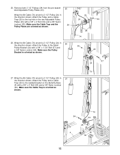
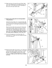
...24) in the direction shown. Remove the 3/8" Nylon Jamnut (63) from the bag labeled "PULLEY BAG 2". Remove a Pro Pulley (26) from the 34 3/8" x 4 3/4" Bolt (60) inserted into the Butterfly Upright (1) in the cable guide on the other. Route the end with the loop through the slot in step 32. Attach the...75 25 60 24 63 Route the Low Pulley Cable (75) under a Pro Pulley (26) as shown. 31 54 26 25 Cable Guide 75 4 50 32. Attach the Pro Pulley and a Cable Trap (25) to the lower hole in the direction shown. Make sure the Cable Trap is oriented as shown. 60 1 24...
...24) in the direction shown. Remove the 3/8" Nylon Jamnut (63) from the bag labeled "PULLEY BAG 2". Remove a Pro Pulley (26) from the 34 3/8" x 4 3/4" Bolt (60) inserted into the Butterfly Upright (1) in the cable guide on the other. Route the end with the loop through the slot in step 32. Attach the...75 25 60 24 63 Route the Low Pulley Cable (75) under a Pro Pulley (26) as shown. 31 54 26 25 Cable Guide 75 4 50 32. Attach the Pro Pulley and a Cable Trap (25) to the lower hole in the direction shown. Make sure the Cable Trap is oriented as shown. 60 1 24...
English Manual
Page 16
... 48 16 72 2 25 24 72 59 Attach the Pulley to the indicated hole in the direction shown. Remove a Pro Pulley (26) from the bag labeled "PULLEY BAG 2". 36 Identify the Press Cable (72). You will begin by attaching the end 63 with a 3/8" x 3 3/4" Bolt (59), a 3/8" Flat ...Washer (48) and a 3/8" Nylon Locknut (50). Wrap the Press Cable (72) around a Pro Pulley (26) in the Press Top Frame (9) with a 3/8" x 2 3/4" Bolt...
... 48 16 72 2 25 24 72 59 Attach the Pulley to the indicated hole in the direction shown. Remove a Pro Pulley (26) from the bag labeled "PULLEY BAG 2". 36 Identify the Press Cable (72). You will begin by attaching the end 63 with a 3/8" x 3 3/4" Bolt (59), a 3/8" Flat ...Washer (48) and a 3/8" Nylon Locknut (50). Wrap the Press Cable (72) around a Pro Pulley (26) in the Press Top Frame (9) with a 3/8" x 2 3/4" Bolt...
English Manual
Page 17
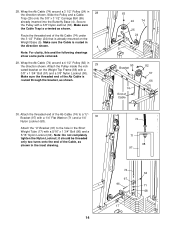
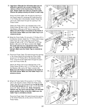
.... Attach the Pulley (24) to the functioning of the Press Upright (2) with a 3/8" x 3 1/4" Bolt (62), a 3/8" Flat Washer (48) and a 3/8" Nylon Locknut (50). Wrap the Press Cable (72) around the pulleys exactly as shown. 41 25 50 72 24 48 62 8 25 50 2 48 Small tube, last hole 27 62 32 72... 62 48 72 8 24 50 42. Attach the "V"-Pulley and a Large Cable Trap (32) to the indicated hole on the inside of 40 the Press Frame. Mount the "V"-Pulley in the direction shown. Attach the Pulley and...
.... Attach the Pulley (24) to the functioning of the Press Upright (2) with a 3/8" x 3 1/4" Bolt (62), a 3/8" Flat Washer (48) and a 3/8" Nylon Locknut (50). Wrap the Press Cable (72) around the pulleys exactly as shown. 41 25 50 72 24 48 62 8 25 50 2 48 Small tube, last hole 27 62 32 72... 62 48 72 8 24 50 42. Attach the "V"-Pulley and a Large Cable Trap (32) to the indicated hole on the inside of 40 the Press Frame. Mount the "V"-Pulley in the direction shown. Attach the Pulley and...
English Manual
Page 18
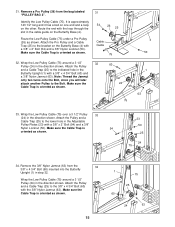
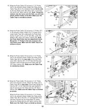
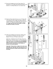
...Use the 3/8" x 4 3/4" Bolt (60) that was inserted in step 42 and secure the Pulley with the 3/8" Nylon Jamnut (63). Wrap the Press Cable (72) around a "V"-Pulley (27) 44 in the hole closest to near side of the Leg Press Lever (83). you will later attach another Pulley to... the near side of the Leg Press Lever (83) with a 3/8" x 4 3/4" Bolt (60) and a 3/8" Nylon Jamnut (63). Wrap the Press Cable (72) around a 3 1/2" Pulley (24) in the direction shown. Use the 3/8" x 4 3/4" Bolt (60) that was inserted in step 43 and secure the Pulley with...
...Use the 3/8" x 4 3/4" Bolt (60) that was inserted in step 42 and secure the Pulley with the 3/8" Nylon Jamnut (63). Wrap the Press Cable (72) around a "V"-Pulley (27) 44 in the hole closest to near side of the Leg Press Lever (83). you will later attach another Pulley to... the near side of the Leg Press Lever (83) with a 3/8" x 4 3/4" Bolt (60) and a 3/8" Nylon Jamnut (63). Wrap the Press Cable (72) around a 3 1/2" Pulley (24) in the direction shown. Use the 3/8" x 4 3/4" Bolt (60) that was inserted in step 43 and secure the Pulley with...
English Manual
Page 19
... the pulleys move smoothly. 72 72 68 97 72 97 96 70 64 71 68 19 47. Route the threaded end of the Cable is routed through the bracket, as shown in the inset drawing. Attach the threaded end of all pulleys and that was mounted on the bracket ... a 1/4" Nylon Locknut (68). Attach the "U"-Bracket (97) to end and make sure that they rest in an earlier step. 72 24 5 48. Wrap the Press Cable (72) over a 4 1/2" Pulley (82) 48 in the Long Weight Tube (70) with a 5/16" x 1 3/4" Bolt (96) and a 5/16" Nylon Locknut (64). Important: Follow all four...
... the pulleys move smoothly. 72 72 68 97 72 97 96 70 64 71 68 19 47. Route the threaded end of the Cable is routed through the bracket, as shown in the inset drawing. Attach the threaded end of all pulleys and that was mounted on the bracket ... a 1/4" Nylon Locknut (68). Attach the "U"-Bracket (97) to end and make sure that they rest in an earlier step. 72 24 5 48. Wrap the Press Cable (72) over a 4 1/2" Pulley (82) 48 in the Long Weight Tube (70) with a 5/16" x 1 3/4" Bolt (96) and a 5/16" Nylon Locknut (64). Important: Follow all four...
English Manual
Page 22
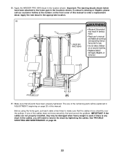
Important: The warning decals shown below have been properly tightened. Apply the WEIDER PRO 9940 decal in the appropriate location. 56 WEIDER PRO 9940 57. Make sure that the cables move smoothly, find and correct the problem. Apply the new decal in the location shown. See TROUBLESHOOTING AND MAINTENANCE on page 25 of this manual ...
Important: The warning decals shown below have been properly tightened. Apply the WEIDER PRO 9940 decal in the appropriate location. 56 WEIDER PRO 9940 57. Make sure that the cables move smoothly, find and correct the problem. Apply the new decal in the location shown. See TROUBLESHOOTING AND MAINTENANCE on page 25 of this manual ...
English Manual
Page 23
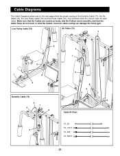
Make sure that the Cables are routed correctly, that the Pulleys move smoothly, and that the Cable Traps do not touch or bind the Cables. Low Pulley Cable (75) Ab Cable (74) 7 3 3 1 2 2 1 4 5 8 5 4 Butterfly Cable (73) 6 4 1 5 2 Cable ID Chart 73, 52" 75, 143.5" 3 74, 224" 72, 389.5" 23 Incorrect cable routing can damage the home gym. The numbers show the proper routing of the Butterfly Cable (73), the Ab Cable (74), the Low Pulley Cable (75) and the Press Cable (72). Cable Diagrams The Cable Diagrams below and on the next page show the correct route for each Cable.
Make sure that the Cables are routed correctly, that the Pulleys move smoothly, and that the Cable Traps do not touch or bind the Cables. Low Pulley Cable (75) Ab Cable (74) 7 3 3 1 2 2 1 4 5 8 5 4 Butterfly Cable (73) 6 4 1 5 2 Cable ID Chart 73, 52" 75, 143.5" 3 74, 224" 72, 389.5" 23 Incorrect cable routing can damage the home gym. The numbers show the proper routing of the Butterfly Cable (73), the Ab Cable (74), the Low Pulley Cable (75) and the Press Cable (72). Cable Diagrams The Cable Diagrams below and on the next page show the correct route for each Cable.
English Manual
Page 25
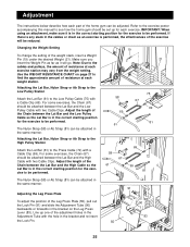
... as it is in the correct starting position for each exercise. Refer to the exercise poster accompanying this manual to the Low Pulley Cable (75) with two Cable Clips. Changing the Weight Setting To change the setting of the exercise will go. Attaching the Lat Bar, Nylon Strap or Ab ...under the desired Weight (21). The Nylon Strap (58) or Ab Strap (81) can be attached between the Lat Bar and the Low Pulley Cable with a Cable Clip (69). Adjustment The instructions below describe how each part of the adjustment holes in the Adjustment Tube with the hole in the bracket and...
... as it is in the correct starting position for each exercise. Refer to the exercise poster accompanying this manual to the Low Pulley Cable (75) with two Cable Clips. Changing the Weight Setting To change the setting of the exercise will go. Attaching the Lat Bar, Nylon Strap or Ab ...under the desired Weight (21). The Nylon Strap (58) or Ab Strap (81) can be attached between the Lat Bar and the Low Pulley Cable with a Cable Clip (69). Adjustment The instructions below describe how each part of the adjustment holes in the Adjustment Tube with the hole in the bracket and...
English Manual
Page 26
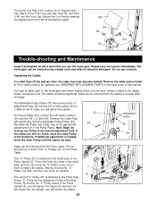
... worn parts immediately. Start by moving it . By moving one more, as needed , move the "V"-Pulley to the third hole. Re-attach the Pulley and Cable Trap to a different set of this manual. Note: Begin by moving one or both pulleys (24) to the appropriate adjustment hole in the Seat Frame... the 3/8" x 2" Bolt (54). ther away from the Front Leg (20) and insert the Curl Post (104) into the Front Leg. To use solvents. If the cables are five adjustment holes in the Pulley Plates. If additional adjustment is needed . 72 27 27 The second "V"-Pulley (27) is felt, the...
... worn parts immediately. Start by moving it . By moving one more, as needed , move the "V"-Pulley to the third hole. Re-attach the Pulley and Cable Trap to a different set of this manual. Note: Begin by moving one or both pulleys (24) to the appropriate adjustment hole in the Seat Frame... the 3/8" x 2" Bolt (54). ther away from the Front Leg (20) and insert the Curl Post (104) into the Front Leg. To use solvents. If the cables are five adjustment holes in the Pulley Plates. If additional adjustment is needed . 72 27 27 The second "V"-Pulley (27) is felt, the...
English Manual
Page 27
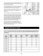
...48 64 62 77 76 90 89 27 The threaded ends on the previous page. The Press Cable (72) is the only cable attached to the 12.5 lb. Then re-attach the "U"Bracket (97). "Top" refers to... the small weight stack. weight plates. When you are tightening the cables, take note that are attached to the weight stacks can be tightened by using the method described above... or by using the Adjustable Pulley Plates (23) as it will be used to tighten the cables. Note: The actual resistance at each station may vary due to differences in individual weight plates ...
...48 64 62 77 76 90 89 27 The threaded ends on the previous page. The Press Cable (72) is the only cable attached to the 12.5 lb. Then re-attach the "U"Bracket (97). "Top" refers to... the small weight stack. weight plates. When you are tightening the cables, take note that are attached to the weight stacks can be tightened by using the method described above... or by using the Adjustable Pulley Plates (23) as it will be used to tighten the cables. Note: The actual resistance at each station may vary due to differences in individual weight plates ...
English Manual
Page 30
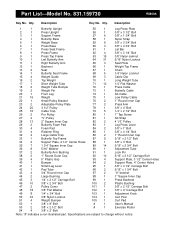
... 1 Small Pulley Bracket 76 2 1" Round Inner Cap 23 2 Adjustable Pulley Plate 77 2 Press Arm 24 20 3 1/2" Pulley 78 1 3/8" x 4" Bolt 25 16 Cable Trap 79 5 1/4" x 2 1/2" Bolt 26 2 Pro Pulley 80 1 1" Tap Screw 27 4 "V"-Pulley 81 1 Ab Strap 28 13 2" Square Inner Cap 82 2 4 1/2" Pulley 29 2 Butterfly Foam Pad 83 1 Leg Press Lever 30...
... 1 Small Pulley Bracket 76 2 1" Round Inner Cap 23 2 Adjustable Pulley Plate 77 2 Press Arm 24 20 3 1/2" Pulley 78 1 3/8" x 4" Bolt 25 16 Cable Trap 79 5 1/4" x 2 1/2" Bolt 26 2 Pro Pulley 80 1 1" Tap Screw 27 4 "V"-Pulley 81 1 Ab Strap 28 13 2" Square Inner Cap 82 2 4 1/2" Pulley 29 2 Butterfly Foam Pad 83 1 Leg Press Lever 30...


