
English Manual
Page 1
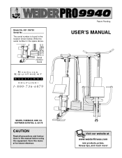
HOFFMAN ESTATES, IL 60179 CAUTION Read all precautions and instructions in this manual before using this manual for future reference. Save this equipment. The serial number is found in the space above. ® Patent Pending USER'S MANUAL Serial Number Decal SEARS, ROEBUCK AND CO. Write the serial number in the location shown below. Visit our website at www.weiderfitness.com new products, prizes, fitness tips, and much more! Model No. 831.159730 Serial No.
HOFFMAN ESTATES, IL 60179 CAUTION Read all precautions and instructions in this manual before using this manual for future reference. Save this equipment. The serial number is found in the space above. ® Patent Pending USER'S MANUAL Serial Number Decal SEARS, ROEBUCK AND CO. Write the serial number in the location shown below. Visit our website at www.weiderfitness.com new products, prizes, fitness tips, and much more! Model No. 831.159730 Serial No.
English Manual
Page 2
... lat bar or ab strap from moving parts. 9. Table of Contents Important Precautions 2 Before You Begin 3 Assembly 4 Cable Diagrams 23 Adjustment 25 Trouble-shooting and Maintenance 26 Weight Resistance Chart 27 Ordering Replacement Parts Back Cover Full 90-day Warranty Back Cover Note: A PART LIST/EXPLODED DRAWING and a PART IDENTIFICATION CHART are attached in the accompanying literature before using the home gym. 3. Always stand on all users of the pulleys. 12. Never release the press arms, butterfly arms, leg lever, lat bar or ab strap while weights...
... lat bar or ab strap from moving parts. 9. Table of Contents Important Precautions 2 Before You Begin 3 Assembly 4 Cable Diagrams 23 Adjustment 25 Trouble-shooting and Maintenance 26 Weight Resistance Chart 27 Ordering Replacement Parts Back Cover Full 90-day Warranty Back Cover Note: A PART LIST/EXPLODED DRAWING and a PART IDENTIFICATION CHART are attached in the accompanying literature before using the home gym. 3. Always stand on all users of the pulleys. 12. Never release the press arms, butterfly arms, leg lever, lat bar or ab strap while weights...
English Manual
Page 3
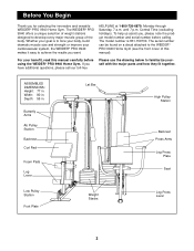
... Pad Foam Pads Leg Lever Lat Bar High Pulley Station Backrest Press Arms Leg Press Plate Seat Low Pulley Station Foot Plate Weight Stacks Leg Press Lever 3 HELPLINE at 1-800-736-6879, Monday through Saturday, 7 a.m. The model number is to achieve the results you , please note the product model number and serial number before using the WEIDER® PRO 9940 Home Gym. until 7 p.m. If you for selecting the innovative and versatile WEIDER® PRO 9940 Home Gym. ASSEMBLED DIMENSIONS: Height: 77 in...
... Pad Foam Pads Leg Lever Lat Bar High Pulley Station Backrest Press Arms Leg Press Plate Seat Low Pulley Station Foot Plate Weight Stacks Leg Press Lever 3 HELPLINE at 1-800-736-6879, Monday through Saturday, 7 a.m. The model number is to achieve the results you , please note the product model number and serial number before using the WEIDER® PRO 9940 Home Gym. until 7 p.m. If you for selecting the innovative and versatile WEIDER® PRO 9940 Home Gym. ASSEMBLED DIMENSIONS: Height: 77 in...
English Manual
Page 4
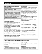
... that connect the moving arms with each assembly stage to walk all parts as shown in the drawings. Cable Assembly This assembly completes the cables and pulleys that assembly stage. • One (1) rubber mallet • Lubricant, such as grease or petroleum jelly, and soapy water • Tape, such as possible, we have included a PART IDENTIFICATION CHART located in the shipping box. Tightening Parts Tighten all the way around the assembled equipment...
... that connect the moving arms with each assembly stage to walk all parts as shown in the drawings. Cable Assembly This assembly completes the cables and pulleys that assembly stage. • One (1) rubber mallet • Lubricant, such as grease or petroleum jelly, and soapy water • Tape, such as possible, we have included a PART IDENTIFICATION CHART located in the shipping box. Tightening Parts Tighten all the way around the assembled equipment...

English Manual
Page 5
..." Nylon Locknuts (64). Insert four 5/16" x 2 1/2" Carriage Bolts (92) up through the indicated holes in the Butterfly Base (4). Locate and open the parts bag labeled "FRAME ASSEMBLY." Insert a 3/8" x 3 1/2" Carriage Bolt (95) up through the hole at the end of each Bolt. Attach the Press Base (6) to the Weight Base (5) with two 5/16" x 2 3/4" Bolts (89), a Support Plate with 3 1/2" center holes (93), and two...
..." Nylon Locknuts (64). Insert four 5/16" x 2 1/2" Carriage Bolts (92) up through the indicated holes in the Butterfly Base (4). Locate and open the parts bag labeled "FRAME ASSEMBLY." Insert a 3/8" x 3 1/2" Carriage Bolt (95) up through the hole at the end of each Bolt. Attach the Press Base (6) to the Weight Base (5) with two 5/16" x 2 3/4" Bolts (89), a Support Plate with 3 1/2" center holes (93), and two...

English Manual
Page 7
... indicated hole in the Press Base (6). Do not tighten the Nylon Jamnut yet. Place the bracket on the Front Leg (20) with a 1" Tap Screw (80). Attach the Bumper (40) to the bracket on the lower end of the Support Frame (3) over the indicated 5/16" x 2 1/2" Carriage Bolts (92) in the Press Base (6). Place the bracket on the Press Upright (2). Press a 1" Square Inner Cap...
... indicated hole in the Press Base (6). Do not tighten the Nylon Jamnut yet. Place the bracket on the Front Leg (20) with a 1" Tap Screw (80). Attach the Bumper (40) to the bracket on the lower end of the Support Frame (3) over the indicated 5/16" x 2 1/2" Carriage Bolts (92) in the Press Base (6). Place the bracket on the Press Upright (2). Press a 1" Square Inner Cap...
English Manual
Page 8
... (64). Slide six Weights (21) onto the Weight Guides (15). Make sure the Weights are turned so the pin grooves point towards the floor. Slide a Top Weight (16) onto the Weight Guides (15). Hand tighten two 5/16" Nylon 28 Locknuts (64) onto the Bolts. Do not tighten the Nylon Locknuts yet. 64 Attach the Press Seat Frame (7) to the Weight Base (5) with the Bolt and a 3/8" Nylon Locknut...
... (64). Slide six Weights (21) onto the Weight Guides (15). Make sure the Weights are turned so the pin grooves point towards the floor. Slide a Top Weight (16) onto the Weight Guides (15). Hand tighten two 5/16" Nylon 28 Locknuts (64) onto the Bolts. Do not tighten the Nylon Locknuts yet. 64 Attach the Press Seat Frame (7) to the Weight Base (5) with the Bolt and a 3/8" Nylon Locknut...
English Manual
Page 9
... indicated brackets on the Weight Tube (70). Slide a 3 1/2" Pulley (24) with 4" center holes (94), and a 3/8" Nylon Locknut (50). Insert the Bolt through the Support Plate (94) and hand tighten a 3/8" Nylon Locknut (50) onto it. Place two Weight Bumpers (51) over the welded pin on the Uprights (1 and 2). Slide ten Weights (21) onto the Weight Guides (15). Attach the Weight Top Frame (66) to...
... indicated brackets on the Weight Tube (70). Slide a 3 1/2" Pulley (24) with 4" center holes (94), and a 3/8" Nylon Locknut (50). Insert the Bolt through the Support Plate (94) and hand tighten a 3/8" Nylon Locknut (50) onto it. Place two Weight Bumpers (51) over the welded pin on the Uprights (1 and 2). Slide ten Weights (21) onto the Weight Guides (15). Attach the Weight Top Frame (66) to...

English Manual
Page 10
... this step to pivot the Press Frame. 17. Lubricate the 3/8" x 8" Bolt (52). Locate and open the parts bag labeled "ARM ASSEMBLY." Attach the Press Frame (8) to the welded tubes on the Press Base (6) with two 5/16" x 2 1/2" Bolts (87) and two 5/16" Nylon Locknuts (64). Press a 1" Round Inner Cap (76) into the top of the four Weight Guides (15) to the bracket on the Press Frame (8). Attach the Press Arm (77...
... this step to pivot the Press Frame. 17. Lubricate the 3/8" x 8" Bolt (52). Locate and open the parts bag labeled "ARM ASSEMBLY." Attach the Press Frame (8) to the welded tubes on the Press Base (6) with two 5/16" x 2 1/2" Bolts (87) and two 5/16" Nylon Locknuts (64). Press a 1" Round Inner Cap (76) into the top of the four Weight Guides (15) to the bracket on the Press Frame (8). Attach the Press Arm (77...
English Manual
Page 11
Repeat this step to the Cable Diagrams and Cable ID Chart on the Left Butterfly Arm (10) with a 3/8" x 1" Bolt (84) and two 3/8" Nylon Jamnuts (63). Locate and open the parts bag labeled "CABLE 19 ASSEMBLY." Remove one "V"-Pulley (27) from the bag. Make sure the teeth on the Cable and the two Nylon...Bracket 73 1 Attach the "V"-Pulley and a Large Cable Trap (32) to the bracket on pages 23 and 24. Wet the lower end of the Butterfly Upright (1) with a hammer. For Cable identification and routing during steps 19 to 49, refer to assemble the Left Butterfly Arm (10, not...
Repeat this step to the Cable Diagrams and Cable ID Chart on the Left Butterfly Arm (10) with a 3/8" x 1" Bolt (84) and two 3/8" Nylon Jamnuts (63). Locate and open the parts bag labeled "CABLE 19 ASSEMBLY." Remove one "V"-Pulley (27) from the bag. Make sure the teeth on the Cable and the two Nylon...Bracket 73 1 Attach the "V"-Pulley and a Large Cable Trap (32) to the bracket on pages 23 and 24. Wet the lower end of the Butterfly Upright (1) with a hammer. For Cable identification and routing during steps 19 to 49, refer to assemble the Left Butterfly Arm (10, not...
English Manual
Page 12
Identify the Ab Cable (74). You will start by attaching the end of the Butterfly Upright (1) with a 3/8" x 2 1/2" Bolt (53) and a 3/8" Nylon Locknut (50). Wrap the Butterfly Cable (73) around a 3 1/2" Pulley (24) in the direction shown. Attach the "V"-Pulley and a Large Cable Trap (32) to the bracket on the Cable and the two Nylon Jamnuts must be mount- ed underneath the welded bracket. 11...
Identify the Ab Cable (74). You will start by attaching the end of the Butterfly Upright (1) with a 3/8" x 2 1/2" Bolt (53) and a 3/8" Nylon Locknut (50). Wrap the Butterfly Cable (73) around a 3 1/2" Pulley (24) in the direction shown. Attach the "V"-Pulley and a Large Cable Trap (32) to the bracket on the Cable and the two Nylon Jamnuts must be mount- ed underneath the welded bracket. 11...
English Manual
Page 15
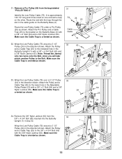
... Low Pulley Cable (75) around a 3 1/2" Pulley (24) in the direction shown. Route the Low Pulley Cable (75) under a Pro Pulley (26) as shown. 23 50 25 24 75 34. Wrap the Low Pulley Cable (75) around a 3 1/2" 32 Pulley (24) in the direction shown. Attach the Pro Pulley and a Cable Trap (25) to the bracket on the Butterfly Base (4). Remove a Pro Pulley (26) from the 34 3/8" x 4 3/4" Bolt (60) inserted into the Butterfly Upright...
... Low Pulley Cable (75) around a 3 1/2" Pulley (24) in the direction shown. Route the Low Pulley Cable (75) under a Pro Pulley (26) as shown. 23 50 25 24 75 34. Wrap the Low Pulley Cable (75) around a 3 1/2" 32 Pulley (24) in the direction shown. Attach the Pro Pulley and a Cable Trap (25) to the bracket on the Butterfly Base (4). Remove a Pro Pulley (26) from the 34 3/8" x 4 3/4" Bolt (60) inserted into the Butterfly Upright...
English Manual
Page 16
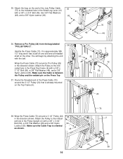
... end of the Press Cable (72) 37 around the 3 1/2" Pulley (24) that is between the Pulley and the welded pin on the Top Frame (9). 9 9 26 72 56 Pin 24 38. Attach the Pulley to the indicated hole in the Press Upright (2) with the ball. 48 Wrap the Press Cable (72) around a 3 1/2" Pulley (24) in the Small Leg Lever (41) 41 with a 3/8" x 3 1/2" Bolt (56), a 3/8" Flat Washer...
... end of the Press Cable (72) 37 around the 3 1/2" Pulley (24) that is between the Pulley and the welded pin on the Top Frame (9). 9 9 26 72 56 Pin 24 38. Attach the Pulley to the indicated hole in the Press Upright (2) with the ball. 48 Wrap the Press Cable (72) around a 3 1/2" Pulley (24) in the Small Leg Lever (41) 41 with a 3/8" x 3 1/2" Bolt (56), a 3/8" Flat Washer...
English Manual
Page 18
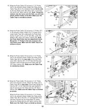
... Leg Press Lever (83). Make sure the Cable Trap is oriented as shown. you will later attach another Pulley to the Leg Press Lever. Note: 48 the Press Seat Frame has five adjustment holes. Wrap the Press Cable (72) around a 3 1/2" Pulley (24) in the direction shown. Use the 3/8" x 4 3/4" Bolt (60) that was inserted in the hole closest to the Bolt. Wrap the Press Cable (72) around a 3 1/2" Pulley 43 (24) in step...
... Leg Press Lever (83). Make sure the Cable Trap is oriented as shown. you will later attach another Pulley to the Leg Press Lever. Note: 48 the Press Seat Frame has five adjustment holes. Wrap the Press Cable (72) around a 3 1/2" Pulley (24) in the direction shown. Use the 3/8" x 4 3/4" Bolt (60) that was inserted in the hole closest to the Bolt. Wrap the Press Cable (72) around a 3 1/2" Pulley 43 (24) in step...
English Manual
Page 22
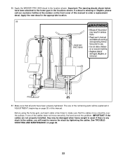
... tightened. The use of this manual to the home gym in the locations shown. Before using the home gym, pull each cable a few times to remove the slack by tightening the cables. If there is used. Apply the WEIDER PRO 9940 decal in the appropriate location. 56 WEIDER PRO 9940 57. If a decal is missing or illegible, please call our customer hotline at the number on page 25 of the remaining parts will need...
... tightened. The use of this manual to the home gym in the locations shown. Before using the home gym, pull each cable a few times to remove the slack by tightening the cables. If there is used. Apply the WEIDER PRO 9940 decal in the appropriate location. 56 WEIDER PRO 9940 57. If a decal is missing or illegible, please call our customer hotline at the number on page 25 of the remaining parts will need...
English Manual
Page 25
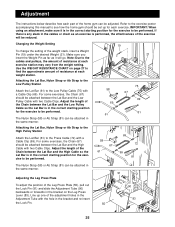
... each exercise. Adjustment The instructions below describe how each part of the home gym can be set up one of the adjustment holes in the Adjustment Tube with the hole in the correct starting position for the exercise to be attached between the Lat Bar and the Low Pulley Cable with two Cable Clips. Adjust the length of the weight stack, insert a Weight Pin (19) under the desired Weight (21). Attaching the Lat Bar, Nylon Strap...
... each exercise. Adjustment The instructions below describe how each part of the home gym can be set up one of the adjustment holes in the Adjustment Tube with the hole in the correct starting position for the exercise to be attached between the Lat Bar and the Low Pulley Cable with two Cable Clips. Adjust the length of the weight stack, insert a Weight Pin (19) under the desired Weight (21). Attaching the Lat Bar, Nylon Strap...
English Manual
Page 26
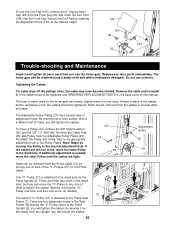
... Pulley to tighten the cables. Remove the cable and re-install it is first used on the Press Upright (2). If there is slack in the cables before resistance is attached to the third hole. To move the same Pulley to the Press Seat Frame (7). Remove the Cable Trap (25) and Pulley from the Upright, you will tighten the cables. There are three free holes in the small tube, and you use the home gym. Do not use...
... Pulley to tighten the cables. Remove the cable and re-install it is first used on the Press Upright (2). If there is slack in the cables before resistance is attached to the third hole. To move the same Pulley to the Press Seat Frame (7). Remove the Cable Trap (25) and Pulley from the Upright, you will tighten the cables. There are three free holes in the small tube, and you use the home gym. Do not use...
English Manual
Page 27
... tighten the cables. Note: The actual resistance at each exercise station. top weight; To tighten the Ab Cable (74), remove the "U"-Bracket (97) from the Short Weight Tube (17) by using the Adjustable Pulley Plates (23) as friction between the cables, pulleys, and weight guides. The Butterfly Cable (73), the Ab Cable (74), and the Low Pulley Cable (75) are all connected to the large weight stack. The Press Cable (72) is the only cable attached...
... tighten the cables. Note: The actual resistance at each exercise station. top weight; To tighten the Ab Cable (74), remove the "U"-Bracket (97) from the Short Weight Tube (17) by using the Adjustable Pulley Plates (23) as friction between the cables, pulleys, and weight guides. The Butterfly Cable (73), the Ab Cable (74), and the Low Pulley Cable (75) are all connected to the large weight stack. The Press Cable (72) is the only cable attached...
English Manual
Page 30
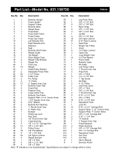
Qty. Description Key No. Specifications are subject to change without notice. Part List-Model No. 831.159730 R0800A Key No. Description 1 1 Butterfly Upright 55 1 Leg Press Plate 2 1 Press Upright 56 1 3/8" x 3 1/2" Bolt 3 1 Support Frame 57 6 3/8" x 1 3/4" Bolt 4 1 Butterfly Base 58 1 Nylon Strap 5 1 Weight Base 59 6 3/8" x 3 3/4" Bolt 6 1 Press Base 60 3 3/8" x 4 3/4" Bolt 7 1 Press Seat Frame 61 1 Lat Bar 8 1 Press Frame 62 4 3/8" x 3 1/4" Bolt 9 1 Press Top Frame 63 15 3/8" Nylon Jamnut 10 1 Left Butterfly Arm 64 31 5/16"...
Qty. Description Key No. Specifications are subject to change without notice. Part List-Model No. 831.159730 R0800A Key No. Description 1 1 Butterfly Upright 55 1 Leg Press Plate 2 1 Press Upright 56 1 3/8" x 3 1/2" Bolt 3 1 Support Frame 57 6 3/8" x 1 3/4" Bolt 4 1 Butterfly Base 58 1 Nylon Strap 5 1 Weight Base 59 6 3/8" x 3 3/4" Bolt 6 1 Press Base 60 3 3/8" x 4 3/4" Bolt 7 1 Press Seat Frame 61 1 Lat Bar 8 1 Press Frame 62 4 3/8" x 3 1/4" Bolt 9 1 Press Top Frame 63 15 3/8" Nylon Jamnut 10 1 Left Butterfly Arm 64 31 5/16"...
English Manual
Page 32
... days from state to the frame. This warranty gives you specific legal rights, and you need help or service, or ordering parts, please be replaced, call the following information: • The MODEL NUMBER of the product (831.159730) • The NAME of the product (WEIDER® PRO 9940 Home Gym) • The KEY NUMBER and DESCRIPTION of the PART (see the PART LIST/EXPLODED DRAWING in Canada © 1999...
... days from state to the frame. This warranty gives you specific legal rights, and you need help or service, or ordering parts, please be replaced, call the following information: • The MODEL NUMBER of the product (831.159730) • The NAME of the product (WEIDER® PRO 9940 Home Gym) • The KEY NUMBER and DESCRIPTION of the PART (see the PART LIST/EXPLODED DRAWING in Canada © 1999...


