
English Manual
Page 1
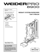
Serial Number Decal WEIGHT SYSTEM EXERCISER Userʼs Manual • Assembly • Operation • Maintenance • Part List and Drawing Sears, Roebuck and Co. Hoffman Estates, IL 60179 CAUTION Read all precautions and instructions in the space above for future reference. Write the serial number in this manual before using this manual for reference. Keep this equipment. Model No. 831.14923.1 Serial No.
Serial Number Decal WEIGHT SYSTEM EXERCISER Userʼs Manual • Assembly • Operation • Maintenance • Part List and Drawing Sears, Roebuck and Co. Hoffman Estates, IL 60179 CAUTION Read all precautions and instructions in the space above for future reference. Write the serial number in this manual before using this manual for reference. Keep this equipment. Model No. 831.14923.1 Serial No.

English Manual
Page 2
... 1-877-992-5999 and request a free replacement decal. TABLE OF CONTENTS WARNING DECAL PLACEMENT 2 IMPORTANT PRECAUTIONS 3 BEFORE YOU BEGIN 4 PART IDENTIFICATION CHART 5 ASSEMBLY 7 ADJUSTMENT 34 WEIGHT RESISTANCE CHART 37 CABLE DIAGRAM 38 MAINTENANCE 39 EXERCISE GUIDELINES 40 PART LIST 43 EXPLODED DRAWING 45 ORDERING REPLACEMENT PARTS Back Cover 90-DAY FULL...
... 1-877-992-5999 and request a free replacement decal. TABLE OF CONTENTS WARNING DECAL PLACEMENT 2 IMPORTANT PRECAUTIONS 3 BEFORE YOU BEGIN 4 PART IDENTIFICATION CHART 5 ASSEMBLY 7 ADJUSTMENT 34 WEIGHT RESISTANCE CHART 37 CABLE DIAGRAM 38 MAINTENANCE 39 EXERCISE GUIDELINES 40 PART LIST 43 EXPLODED DRAWING 45 ORDERING REPLACEMENT PARTS Back Cover 90-DAY FULL...
English Manual
Page 3
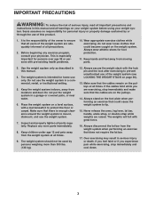
... the risk of serious injury, read all important precautions and instructions in this manual. 4. do not wear loose clothes that could cause the weight system to ensure that the cables remain on a level surface, with great force. 16. Make sure that the cables are raised. The...this product. 1. Over exercising may result in a garage or covered patio, or near water. 6. Do not put the weight system in serious injury or death. Always secure the weight stack with pre-existing health problems. 10. If you feel faint or if you are exercising, stop immediately and cool down...
... the risk of serious injury, read all important precautions and instructions in this manual. 4. do not wear loose clothes that could cause the weight system to ensure that the cables remain on a level surface, with great force. 16. Make sure that the cables are raised. The...this product. 1. Over exercising may result in a garage or covered patio, or near water. 6. Do not put the weight system in serious injury or death. Always secure the weight stack with pre-existing health problems. 10. If you feel faint or if you are exercising, stop immediately and cool down...
English Manual
Page 4
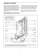
... muscle size and strength, or improve your benefit, read this manual carefully before contacting us assist you want. If you for selecting the versatile WEIDER PRO™ 8900 weight system. Before reading further, please review the drawing below and familiarize yourself with the parts that are used relative to right and left side" are...
... muscle size and strength, or improve your benefit, read this manual carefully before contacting us assist you want. If you for selecting the versatile WEIDER PRO™ 8900 weight system. Before reading further, please review the drawing below and familiarize yourself with the parts that are used relative to right and left side" are...
English Manual
Page 7
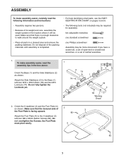
...must pivot easily. 4 82 7 Orient the Base (1) and the Side Stabilizers (2) as shown. Make sure that there is enough clearance to walk around the weight system. • Place all parts in the location where it will be more convenient if you have a socket set, a set of open-end or closed...-end wrenches, or a set of ratchet wrenches. 1. Do not dispose of its weight and size, assemble the weight system in a cleared area and remove the packing materials. Do not fully tighten the Locknuts yet. 1 2 74 74 1 78 2 78 Warning Decal 2....
...must pivot easily. 4 82 7 Orient the Base (1) and the Side Stabilizers (2) as shown. Make sure that there is enough clearance to walk around the weight system. • Place all parts in the location where it will be more convenient if you have a socket set, a set of open-end or closed...-end wrenches, or a set of ratchet wrenches. 1. Do not dispose of its weight and size, assemble the weight system in a cleared area and remove the packing materials. Do not fully tighten the Locknuts yet. 1 2 74 74 1 78 2 78 Warning Decal 2....
English Manual
Page 11
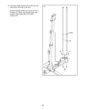
Orient the Weight Guides (31) so that the indicated holes are closer to the floor. 10 Insert the Weight Guides (31) into the holes in the Base (1). Attach each Weight Guide with an M10 x 63mm Bolt (89) and an M10 Locknut (74). Holes 31 74 74 1 89 11 10.
Orient the Weight Guides (31) so that the indicated holes are closer to the floor. 10 Insert the Weight Guides (31) into the holes in the Base (1). Attach each Weight Guide with an M10 x 63mm Bolt (89) and an M10 Locknut (74). Holes 31 74 74 1 89 11 10.
English Manual
Page 12
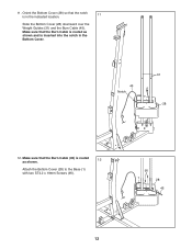
Make sure that the Burn Cable is routed as shown. 12 Attach the Bottom Cover (28) to the Base (1) with two ST4.2 x 19mm Screws (90). 90 1 28 45 12 Make sure that the Burn Cable (45) is routed as shown and is in the Bottom Cover. 45 Notch 31 28 12. Orient the Bottom Cover (28) so that the notch is inserted into the notch in the indicated location. 11 Slide the Bottom Cover (28) downward over the Weight Guides (31) and the Burn Cable (45). 11.
Make sure that the Burn Cable is routed as shown. 12 Attach the Bottom Cover (28) to the Base (1) with two ST4.2 x 19mm Screws (90). 90 1 28 45 12 Make sure that the Burn Cable (45) is routed as shown and is in the Bottom Cover. 45 Notch 31 28 12. Orient the Bottom Cover (28) so that the notch is inserted into the notch in the indicated location. 11 Slide the Bottom Cover (28) downward over the Weight Guides (31) and the Burn Cable (45). 11.
English Manual
Page 13
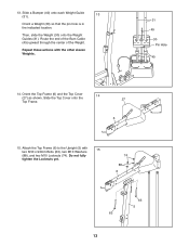
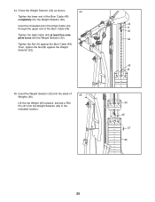
... the Top Cover (27) as shown. Route the end of the Burn Cable (45) upward through the center of the Weight. Attach the Top Frame (6) to the Upright (5) with the other eleven Weights. 31 45 30 Pin Hole 40 14. Repeat these actions with 15 two M10 x 93mm Bolts (63), two M10... Cover onto the 14 27 Top Frame. 6 15. Do not fully tighten the Locknuts yet. 74 88 6 63 13 63 5 Slide a Bumper (40) onto each Weight Guide (31). 13 Orient a Weight (30) so that the pin hole is in the indicated location.
... the Top Cover (27) as shown. Route the end of the Burn Cable (45) upward through the center of the Weight. Attach the Top Frame (6) to the Upright (5) with the other eleven Weights. 31 45 30 Pin Hole 40 14. Repeat these actions with 15 two M10 x 93mm Bolts (63), two M10... Cover onto the 14 27 Top Frame. 6 15. Do not fully tighten the Locknuts yet. 74 88 6 63 13 63 5 Slide a Bumper (40) onto each Weight Guide (31). 13 Orient a Weight (30) so that the pin hole is in the indicated location.
English Manual
Page 14
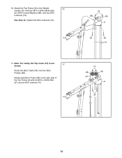
See step 15. Attach the Top Frame (6) to the right side of the Top Frame (6) with two M10 x 43mm Bolts (65), two M10 Curved Washers (86), and two M10 Locknuts (74). Note: For clarity, the Top Cover (27) is not shown. 17 Route the Burn Cable (45) over two Burn Pulleys (68). Tighten the M10 Locknuts (74). 17. Attach each Burn Pulley (68) to the Weight 16 Guides (31) with an M10 x 40mm Bolt (97) and an M10 Locknut (74). 74 86 86 6 65 65 31 74 68 68 45 6 97 14 16.
See step 15. Attach the Top Frame (6) to the right side of the Top Frame (6) with two M10 x 43mm Bolts (65), two M10 Curved Washers (86), and two M10 Locknuts (74). Note: For clarity, the Top Cover (27) is not shown. 17 Route the Burn Cable (45) over two Burn Pulleys (68). Tighten the M10 Locknuts (74). 17. Attach each Burn Pulley (68) to the Weight 16 Guides (31) with an M10 x 40mm Bolt (97) and an M10 Locknut (74). 74 86 86 6 65 65 31 74 68 68 45 6 97 14 16.
English Manual
Page 25
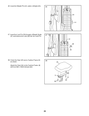
44. Insert the threaded end of the High Cable (44) through the upper end of Weights (30). 45 Lift the top Weight (30) upward, and tap a Roll Pin (37) into the Weight Selector (32) in the indicated location. 44 A 45 32 45 B 30 32 37 30 25 Then, tighten the Nut (B) ... Tighten the lower end of the Burn Cable (45) completely into the Weight Selector (32). Tighten the High Cable (44) at least five complete turns into the Weight Selector (32). Tighten the Nut (A) against the Weight Selector (32). 45. Insert the Weight Selector (32) into the stack of the Burn Cable (45).
44. Insert the threaded end of the High Cable (44) through the upper end of Weights (30). 45 Lift the top Weight (30) upward, and tap a Roll Pin (37) into the Weight Selector (32) in the indicated location. 44 A 45 32 45 B 30 32 37 30 25 Then, tighten the Nut (B) ... Tighten the lower end of the Burn Cable (45) completely into the Weight Selector (32). Tighten the High Cable (44) at least five complete turns into the Weight Selector (32). Tighten the Nut (A) against the Weight Selector (32). 45. Insert the Weight Selector (32) into the stack of the Burn Cable (45).
English Manual
Page 26
Orient the Seat (24) and a Cushion Frame (9) as shown. 48 24 Attach the Seat (24) to the Cushion Frame (9) with four M6 x 16mm Screws (62). 9 62 62 26 46. Insert the Weight Pin (41) under a Weight (30). 46 30 41 47. Insert the Lock Pin (39) through a Weight Guide (31) and secure the Lock (38) into the Lock Pin. 47 31 38 39 48.
Orient the Seat (24) and a Cushion Frame (9) as shown. 48 24 Attach the Seat (24) to the Cushion Frame (9) with four M6 x 16mm Screws (62). 9 62 62 26 46. Insert the Weight Pin (41) under a Weight (30). 46 30 41 47. Insert the Lock Pin (39) through a Weight Guide (31) and secure the Lock (38) into the Lock Pin. 47 31 38 39 48.
English Manual
Page 33
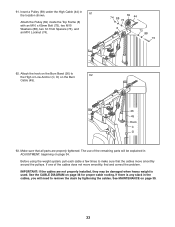
..., pull each cable a few times to make sure that all parts are not properly installed, they may be damaged when heavy weight is any slack in the cables, you will be explained in the location shown. 61 Attach the Pulley (69) inside the Top Frame (6) with an ...
..., pull each cable a few times to make sure that all parts are not properly installed, they may be damaged when heavy weight is any slack in the cables, you will be explained in the location shown. 61 Attach the Pulley (69) inside the Top Frame (6) with an ...
English Manual
Page 34
...accompanying exercise guide to find the approximate amount of resistance at each exercise station may vary from your exercise program. Use the WEIGHT 41 RESISTANCE CHART on page 40 for several exercises. Make sure that the Adjustment Knob is used. See the EXERCISE GUIDELINES on page...To adjust the Seat (24), remove the Adjustment Knob (29), move the Seat to adjust the weight system. Insert the Weight Pin so that all parts are properly tightened each weight station. Replace any worn parts immediately. ADJUSTMENT This section explains how to the desired position, and ...
...accompanying exercise guide to find the approximate amount of resistance at each exercise station may vary from your exercise program. Use the WEIGHT 41 RESISTANCE CHART on page 40 for several exercises. Make sure that the Adjustment Knob is used. See the EXERCISE GUIDELINES on page...To adjust the Seat (24), remove the Adjustment Knob (29), move the Seat to adjust the weight system. Insert the Weight Pin so that all parts are properly tightened each weight station. Replace any worn parts immediately. ADJUSTMENT This section explains how to the desired position, and ...
English Manual
Page 35
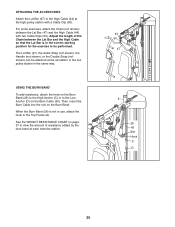
... (6). ATTACHING THE ACCESSORIES Attach the Lat Bar (47) to the High Cable (44) at the high pulley station with two Cable Clips (50). See the WEIGHT RESISTANCE CHART on page 37 to the Low Anchor (D) on the Burn Cable (45). USING THE BURN BAND To add resistance, attach the hook on...
... (6). ATTACHING THE ACCESSORIES Attach the Lat Bar (47) to the High Cable (44) at the high pulley station with two Cable Clips (50). See the WEIGHT RESISTANCE CHART on page 37 to the Low Anchor (D) on the Burn Cable (45). USING THE BURN BAND To add resistance, attach the hook on...
English Manual
Page 36
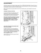
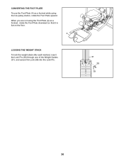
When you are not using the Foot Plate (4) as a footrest while using the low pulley station, rotate the Foot Plate upward. CONVERTING THE FOOT PLATE To use the Foot Plate (4) as a footrest, rotate the Foot Plate downward so that it is flat on the floor. 4 LOCKING THE WEIGHT STACK To lock the weight stack after each workout, insert the Lock Pin (39) through one of the Weight Guides (31), and secure the Lock (38) into the Lock Pin. 31 38 39 36
When you are not using the Foot Plate (4) as a footrest while using the low pulley station, rotate the Foot Plate upward. CONVERTING THE FOOT PLATE To use the Foot Plate (4) as a footrest, rotate the Foot Plate downward so that it is flat on the floor. 4 LOCKING THE WEIGHT STACK To lock the weight stack after each workout, insert the Lock Pin (39) through one of the Weight Guides (31), and secure the Lock (38) into the Lock Pin. 31 38 39 36
English Manual
Page 37
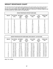
... 125 148 160 172 193 201 PRESS ARM (lbs.) 26 36 51 57 69 82 93 105 117 128 142 162 WEIGHT RESISTANCE WITH BURN BAND (HIGH ANCHOR / LOW ANCHOR) WEIGHT 1 2 3 4 5 6 7 8 9 10 11 12 AB STATION BUTTERFLY (lbs.) ARM (lbs.) 98 / 126 112 / 139 126 / 151 140 / 172 149 / 181 ...194 189 / 212 199 / 226 210 / 237 Note: 1 lb. = 0.45 kg 37 Note: The weight resistance shown for the butterfly arm station is for each exercise station. weights. WEIGHT RESISTANCE CHART The chart below shows the approximate weight resistance at each station may vary due to differences in the left column refer to...
... 125 148 160 172 193 201 PRESS ARM (lbs.) 26 36 51 57 69 82 93 105 117 128 142 162 WEIGHT RESISTANCE WITH BURN BAND (HIGH ANCHOR / LOW ANCHOR) WEIGHT 1 2 3 4 5 6 7 8 9 10 11 12 AB STATION BUTTERFLY (lbs.) ARM (lbs.) 98 / 126 112 / 139 126 / 151 140 / 172 149 / 181 ...194 189 / 212 199 / 226 210 / 237 Note: 1 lb. = 0.45 kg 37 Note: The weight resistance shown for the butterfly arm station is for each exercise station. weights. WEIGHT RESISTANCE CHART The chart below shows the approximate weight resistance at each station may vary due to differences in the left column refer to...
English Manual
Page 38
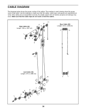
Make sure that the cables, cable traps, and guards are not assembled correctly, the weight system will not function properly and damage may occur. If the cables are assembled correctly. CABLE DIAGRAM The drawings below shows the proper routing of ...
Make sure that the cables, cable traps, and guards are not assembled correctly, the weight system will not function properly and damage may occur. If the cables are assembled correctly. CABLE DIAGRAM The drawings below shows the proper routing of ...
English Manual
Page 39
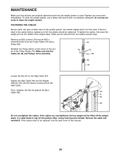
... slack in the cables before resistance is removed from two Pulley Plates (70) and a Pulley (69). To tighten the cables, first insert the weight pin into the Weight Selector (32) until the slack is felt, the cables should be removed from the cables several ways: Remove an M10 Locknut (74) and an... High Cable (44). Slack can stretch slightly when it is used . If the cables need to the center of the weight stack. Make sure that all parts are overtightened, the top weight will be replaced, see the back cover of this manual. 39 Tighten the High Cable (44) into the middle of...
... slack in the cables before resistance is removed from two Pulley Plates (70) and a Pulley (69). To tighten the cables, first insert the weight pin into the Weight Selector (32) until the slack is felt, the cables should be removed from the cables several ways: Remove an M10 Locknut (74) and an... High Cable (44). Slack can stretch slightly when it is used . If the cables need to the center of the weight stack. Make sure that all parts are overtightened, the top weight will be replaced, see the back cover of this manual. 39 Tighten the High Cable (44) into the middle of...
English Manual
Page 40
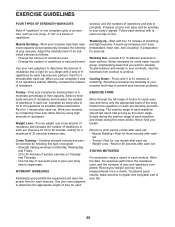
...each set . Complete as many sets of 15 to 20 repetitions as the return stage. Progress at least one day of rest. Weight Loss-To lose weight, use a low amount of resistance and increase the number of repetitions in each set . • Toning-Rest for one sit-up... aerobic exercise by using high amounts of resistance. Never hold your exercise. To achieve good results, make exercise a regular and enjoyable part of your weight and key body measurements once a month. EXERCISE GUIDELINES FOUR TYPES OF STRENGTH WORKOUTS Note: A "repetition" is one complete cycle of an exercise,...
...each set . Complete as many sets of 15 to 20 repetitions as the return stage. Progress at least one day of rest. Weight Loss-To lose weight, use a low amount of resistance and increase the number of repetitions in each set . • Toning-Rest for one sit-up... aerobic exercise by using high amounts of resistance. Never hold your exercise. To achieve good results, make exercise a regular and enjoyable part of your weight and key body measurements once a month. EXERCISE GUIDELINES FOUR TYPES OF STRENGTH WORKOUTS Note: A "repetition" is one complete cycle of an exercise,...
English Manual
Page 43
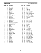
... Bracket Left Butterfly Pad Right Butterfly Pad Seat Backrest Burn Band Top Cover Bottom Cover Adjustment Knob Weight Weight Guide Weight Selector Center Shroud Right Side Shroud Foam Pad Pad Cap Roll Pin Lock Lock Pin Bumper Weight Pin Press Arm Spacer Low Cable High Cable Burn Cable Model No. 831.14923.1 R0812A Key...
... Bracket Left Butterfly Pad Right Butterfly Pad Seat Backrest Burn Band Top Cover Bottom Cover Adjustment Knob Weight Weight Guide Weight Selector Center Shroud Right Side Shroud Foam Pad Pad Cap Roll Pin Lock Lock Pin Bumper Weight Pin Press Arm Spacer Low Cable High Cable Burn Cable Model No. 831.14923.1 R0812A Key...


