

English Manual
Page 1
Model No. 831.159301 Serial No. Save this equipment. Write the serial number in this manual before using this manual for reference. WEIGHT SYSTEM EXERCISER User's Manual Serial Number Decal (under seat) • Assembly • Adjustments • Troubleshooting • Part List and Drawing CAUTION Read all precautions and instructions in the space above for future reference. Patent Pending Sears, Roebuck and Co., Hoffman Estates, IL 60179
Model No. 831.159301 Serial No. Save this equipment. Write the serial number in this manual before using this manual for reference. WEIGHT SYSTEM EXERCISER User's Manual Serial Number Decal (under seat) • Assembly • Adjustments • Troubleshooting • Part List and Drawing CAUTION Read all precautions and instructions in the space above for future reference. Patent Pending Sears, Roebuck and Co., Hoffman Estates, IL 60179

English Manual
Page 2
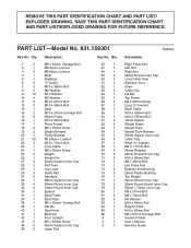
TABLE OF CONTENTS IMPORTANT PRECAUTIONS 3 BEFORE YOU BEGIN 4 ASSEMBLY 5 ADJUSTMENTS 13 WEIGHT RESISTANCE CHART 15 TROUBLESHOOTING 16 CABLE DIAGRAMS 17 EXERCISE GUIDELINES 18 ORDERING REPLACEMENT PARTS Back Cover FULL 90-DAY WARRANTY Back Cover Note: A PART IDENTIFICATION CHART and a PART LIST/EXPLODED DRAWING are attached to the center of this manual. Remove the PART IDENTIFICATION CHART and PART LIST/EXPLODED DRAWING before beginning assembly. 2
TABLE OF CONTENTS IMPORTANT PRECAUTIONS 3 BEFORE YOU BEGIN 4 ASSEMBLY 5 ADJUSTMENTS 13 WEIGHT RESISTANCE CHART 15 TROUBLESHOOTING 16 CABLE DIAGRAMS 17 EXERCISE GUIDELINES 18 ORDERING REPLACEMENT PARTS Back Cover FULL 90-DAY WARRANTY Back Cover Note: A PART IDENTIFICATION CHART and a PART LIST/EXPLODED DRAWING are attached to the center of this manual. Remove the PART IDENTIFICATION CHART and PART LIST/EXPLODED DRAWING before beginning assembly. 2

English Manual
Page 3
... our toll-free Customer Service Department at all instructions in this area. 9. Never release the press arm, butterfly arms, leg lever, lat bar, or nylon strap while weights are exercising, stop immediately and begin cooling down. 15. Decal 1 WARNING: Before beginning this product. 3 This is designed to protect the floor. 5. Use the weight system only on the pulleys at any commercial, rental, or institutional setting. 4. Keep hands...
... our toll-free Customer Service Department at all instructions in this area. 9. Never release the press arm, butterfly arms, leg lever, lat bar, or nylon strap while weights are exercising, stop immediately and begin cooling down. 15. Decal 1 WARNING: Before beginning this product. 3 This is designed to protect the floor. 5. Use the weight system only on the pulleys at any commercial, rental, or institutional setting. 4. Keep hands...

English Manual
Page 4
... benefit, read this manual carefully before calling. ASSEMBLED DIMENSIONS: Height: 76 in . Width: 38 in . Butterfly Arms Right Side Backrest Press Arm Decal 2 Leg Lever Decal 1 High Pulley Station Lat Bar Left Side Seat Weight Stack Foot Plate Low Pulley Station Note: The terms "right side" and "left on a decal attached to develop every major muscle group of the body. The serial number can be found on...
... benefit, read this manual carefully before calling. ASSEMBLED DIMENSIONS: Height: 76 in . Width: 38 in . Butterfly Arms Right Side Backrest Press Arm Decal 2 Leg Lever Decal 1 High Pulley Station Lat Bar Left Side Seat Weight Stack Foot Plate Low Pulley Station Note: The terms "right side" and "left on a decal attached to develop every major muscle group of the body. The serial number can be found on...

English Manual
Page 5
... this manual. ASSEMBLY Make Things Easier for assembly: • Two adjustable wrenches • One rubber mallet • One standard screwdriver • One Phillips screwdriver • Lubricant, such as shown in the drawings. • For help identifying small parts, use the PART IDENTIFICATION CHART at the center of the packing materials until assembly is completed. • Tighten all parts as you assemble them, unless instructed...
... this manual. ASSEMBLY Make Things Easier for assembly: • Two adjustable wrenches • One rubber mallet • One standard screwdriver • One Phillips screwdriver • Lubricant, such as shown in the drawings. • For help identifying small parts, use the PART IDENTIFICATION CHART at the center of the packing materials until assembly is completed. • Tighten all parts as you assemble them, unless instructed...

English Manual
Page 6
... Weight. Lubricate the insides of the Weights are turned so the large pin grooves are resting in the pin grooves in the Top Weight (76). Make sure that the pins on the Weight Bumpers (19). Attach the two Weight Guides (62) inside of Weights (25). Slide the Top Weight onto the Weight Guides (62). 6 4 1 62 Lubricate Pin Pin Groove Pin Groove 19 21 76 63 64 25 9 11 9 61 5 2. Press the Weight...
... Weight. Lubricate the insides of the Weights are turned so the large pin grooves are resting in the pin grooves in the Top Weight (76). Make sure that the pins on the Weight Bumpers (19). Attach the two Weight Guides (62) inside of Weights (25). Slide the Top Weight onto the Weight Guides (62). 6 4 1 62 Lubricate Pin Pin Groove Pin Groove 19 21 76 63 64 25 9 11 9 61 5 2. Press the Weight...

English Manual
Page 7
... Press Frame into place on the Press Frame (17). Attach the Right Press Arm (46) to the indicated side of the Weight Guides (62) to the Front Upright 4 (42) with two M8 x70mm Bolts (81), a Support Plate (84), and two M8 Nylon Locknuts (3). 81 84 Attach the upper ends of the Press Frame (17) with the hole in steps 2 and 4. 9 3 9 60 42 62 Arm Assembly 5. Press...
... Press Frame into place on the Press Frame (17). Attach the Right Press Arm (46) to the indicated side of the Weight Guides (62) to the Front Upright 4 (42) with two M8 x70mm Bolts (81), a Support Plate (84), and two M8 Nylon Locknuts (3). 81 84 Attach the upper ends of the Press Frame (17) with the hole in steps 2 and 4. 9 3 9 60 42 62 Arm Assembly 5. Press...

English Manual
Page 8
.... Set two 25mm Retainers (69) on the Base (4) and under a 90mm Pulley 9 (15) Attach the Pulley and a Cable Trap (66) to verify proper cable routing. Make sure that the upper end of the Left Arm is in the inset drawing. Locate the Short Cable (58). Wet the end of a 25mm Round Cover Cap (70). Route the Short Cable (58) under the Press Frame (17). Lubricate...
.... Set two 25mm Retainers (69) on the Base (4) and under a 90mm Pulley 9 (15) Attach the Pulley and a Cable Trap (66) to verify proper cable routing. Make sure that the upper end of the Left Arm is in the inset drawing. Locate the Short Cable (58). Wet the end of a 25mm Round Cover Cap (70). Route the Short Cable (58) under the Press Frame (17). Lubricate...

English Manual
Page 9
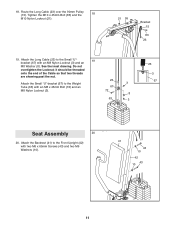
... drawing. Attach the Pulley and a Cable Trap (66) to hold the Cable in the Front Upright (42) with an M10 x 95mm Bolt (71), an M10 Washer (9), and an M10 Nylon Locknut (21). Locate the Long Cable (23). Route the Short Cable (58) under a 90mm Pulley 11 (15). Route the Long Cable over a 90mm Pulley (15). Make sure that the Cable is between the Pulley and the...
... drawing. Attach the Pulley and a Cable Trap (66) to hold the Cable in the Front Upright (42) with an M10 x 95mm Bolt (71), an M10 Washer (9), and an M10 Nylon Locknut (21). Locate the Long Cable (23). Route the Short Cable (58) under a 90mm Pulley 11 (15). Route the Long Cable over a 90mm Pulley (15). Make sure that the Cable is between the Pulley and the...
English Manual
Page 11
Tighten the M10 x 45mm Bolt (83) and the 18 M10 Nylon Locknut (21). 21 55 Bracket 15 83 23 19. Attach the Long Cable (23) to the Weight Tube (63) with an M8 x 45mm Bolt (72) and an 3 67 M8 Nylon Locknut (3). 72 8 63 3 23 3 67 Seat Assembly 20 20. See the inset drawing. it should ... bracket (67) with two M6 x 65mm Screws (43) and two M6 Washers (10). 41 43 10 42 43 10 11 Attach the Backrest (41) to the Front Upright (42) with an M8 Nylon Locknut (3) and an M8 Washer (8). 18. Do not overtighten the Locknut; Route the Long Cable (23) over the 90mm Pulley (15).
Tighten the M10 x 45mm Bolt (83) and the 18 M10 Nylon Locknut (21). 21 55 Bracket 15 83 23 19. Attach the Long Cable (23) to the Weight Tube (63) with an M8 x 45mm Bolt (72) and an 3 67 M8 Nylon Locknut (3). 72 8 63 3 23 3 67 Seat Assembly 20 20. See the inset drawing. it should ... bracket (67) with two M6 x 65mm Screws (43) and two M6 Washers (10). 41 43 10 42 43 10 11 Attach the Backrest (41) to the Front Upright (42) with an M8 Nylon Locknut (3) and an M8 Washer (8). 18. Do not overtighten the Locknut; Route the Long Cable (23) over the 90mm Pulley (15).
English Manual
Page 12
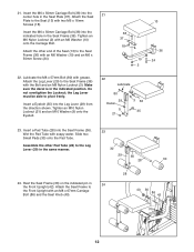
... Upright with an M8 x 67mm Carriage Bolt (86) and the Seat Knob (40). 28 40 36 86 42 Pin 12 Do not overtighten the Locknut; Insert a Pad Tube (28) into the Leg Lever (29) from the direction shown. 21. Insert a Eyebolt (35) into the Seat Frame (36). 23 Wet the Pad Tube with two M6 x 16mm Screws (18). Attach the Seat...
... Upright with an M8 x 67mm Carriage Bolt (86) and the Seat Knob (40). 28 40 36 86 42 Pin 12 Do not overtighten the Locknut; Insert a Pad Tube (28) into the Leg Lever (29) from the direction shown. 21. Insert a Eyebolt (35) into the Seat Frame (36). 23 Wet the Pad Tube with two M6 x 16mm Screws (18). Attach the Seat...

English Manual
Page 13
... the problem. Use the WEIGHT RESISTANCE CHART on page 15 to see TROUBLESHOOTING on page 16. See the CABLE DIAGRAMS on page 14.) 23 53 52 53 54 13 See the exercise guide accompanying this manual for each cable a few times to the Long Cable (23) with an accessory. (See ATTACHING AND REMOVING THE SEAT, on page 17 of the weight stack can be set up for proper cable routing...
... the problem. Use the WEIGHT RESISTANCE CHART on page 15 to see TROUBLESHOOTING on page 16. See the CABLE DIAGRAMS on page 14.) 23 53 52 53 54 13 See the exercise guide accompanying this manual for each cable a few times to the Long Cable (23) with an accessory. (See ATTACHING AND REMOVING THE SEAT, on page 17 of the weight stack can be set up for proper cable routing...

English Manual
Page 14
... off the Front Upright (42). ATTACHING THE LEG LEVER TO THE LOW PULLEY STATION To use the Leg Lever (29), the seat must also be removed when removing the Short Cable from the Eyebolt. 40 36 13 86 42 Pin 29 29 35 53 58 14 Next, remove the Seat Knob (40) and the M8 x 67mm Carriage Bolt (86) from the weight stack. First, make sure...
... off the Front Upright (42). ATTACHING THE LEG LEVER TO THE LOW PULLEY STATION To use the Leg Lever (29), the seat must also be removed when removing the Short Cable from the Eyebolt. 40 36 13 86 42 Pin 29 29 35 53 58 14 Next, remove the Seat Knob (40) and the M8 x 67mm Carriage Bolt (86) from the weight stack. First, make sure...
English Manual
Page 15
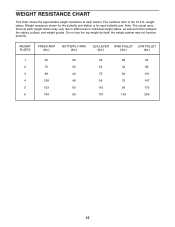
Weight resistance shown for the butterfly arm station is for each station. The numbers refer to differences in individual weight plates, as well as friction between the cables, pulleys, and weight guides. weight plates. WEIGHT PLATES PRESS ARM (lbs.) BUTTERFLY ARM (lbs.) LEG LEVER HIGH PULLEY LOW PULLEY (lbs.) (lbs.) (lbs.)...use the top weight by itself; the weight system may vary due to the 12.5 lb. WEIGHT RESISTANCE CHART This chart shows the approximate weight resistance at each weight station may not function properly. Note: The actual resistance at each butterfly arm...
Weight resistance shown for the butterfly arm station is for each station. The numbers refer to differences in individual weight plates, as well as friction between the cables, pulleys, and weight guides. weight plates. WEIGHT PLATES PRESS ARM (lbs.) BUTTERFLY ARM (lbs.) LEG LEVER HIGH PULLEY LOW PULLEY (lbs.) (lbs.) (lbs.)...use the top weight by itself; the weight system may vary due to the 12.5 lb. WEIGHT RESISTANCE CHART This chart shows the approximate weight resistance at each weight station may not function properly. Note: The actual resistance at each butterfly arm...

English Manual
Page 16
... cable used on the weight system, can be replaced, see ORDERING REPLACEMENT PARTS on the back cover of this you may need to slip off the weight stack. Remove the cable and re-install it is positioned to the lower hole in the Long "U"-bracket (57). TIGHTENING THE CABLES Woven cable, the type of the Short Cable (58). To do this manual. 16 Re-attach the Pulley and Cable Trap. Note: If a cable...
... cable used on the weight system, can be replaced, see ORDERING REPLACEMENT PARTS on the back cover of this you may need to slip off the weight stack. Remove the cable and re-install it is positioned to the lower hole in the Long "U"-bracket (57). TIGHTENING THE CABLES Woven cable, the type of the Short Cable (58). To do this manual. 16 Re-attach the Pulley and Cable Trap. Note: If a cable...

English Manual
Page 17
If the cables have been assembled correctly. Make sure that the two cables and the cable traps have not been correctly routed, the weight system will not function properly and damage may occur. The numbers show the proper routing of the Long Cable (23) and the Short Cable (58). CABLE DIAGRAMS The cable diagrams show the correct route for each cable. Use the diagram to make sure that the cable traps do not touch or bind the cables. 5 4 7 1 2 3 Long Cable (23) 6 5 8 Short Cable (58) 4 3 2 1 17
If the cables have been assembled correctly. Make sure that the two cables and the cable traps have not been correctly routed, the weight system will not function properly and damage may occur. The numbers show the proper routing of the Long Cable (23) and the Short Cable (58). CABLE DIAGRAMS The cable diagrams show the correct route for each cable. Use the diagram to make sure that the cable traps do not touch or bind the cables. 5 4 7 1 2 3 Long Cable (23) 6 5 8 Short Cable (58) 4 3 2 1 17

English Manual
Page 18
... amount of resistance used • by changing the number of resistance. Select exercises for 1 minute after each set . The exertion stage of the muscles affected. You can adjust the intensity level of an individual exercise in any time while exercising, stop immediately and begin cooling down. The combination of strength training and aerobic exercise will find the names of an effective exercise program. You should...
... amount of resistance used • by changing the number of resistance. Select exercises for 1 minute after each set . The exertion stage of the muscles affected. You can adjust the intensity level of an individual exercise in any time while exercising, stop immediately and begin cooling down. The combination of strength training and aerobic exercise will find the names of an effective exercise program. You should...

English Manual
Page 19
... the proper form for each set . Soleus (front of sets and repetitions completed. List the date, the exercises performed, the resistance used, and the numbers of calf) L. Biceps (front of thigh) J. Sartorius (front of arm) D. Posterior Deltoid (shoulder) R. Spinae Erectors (lower back) U. Gluteus Maximus (buttocks) W. The ideal resting periods are: • Rest for three minutes after each set for a weight loss workout. A B C D E F G H I . Hip...
... the proper form for each set . Soleus (front of sets and repetitions completed. List the date, the exercises performed, the resistance used, and the numbers of calf) L. Biceps (front of thigh) J. Sartorius (front of arm) D. Posterior Deltoid (shoulder) R. Spinae Erectors (lower back) U. Gluteus Maximus (buttocks) W. The ideal resting periods are: • Rest for three minutes after each set for a weight loss workout. A B C D E F G H I . Hip...
English Manual
Page 22
... Screw Weight Bumper Pulley Bracket M10 Nylon Locknut M10 x 75mm Bolt Long Cable M6 x 50mm Screw Weight Weight Pin 50mm Square Inner Cap Pad Tube Leg Lever Small Pad Handgrip 38mm Square Inner Cap 50mm Round Inner Cap 19mm Round Inner Cap Eyebolt Seat Frame Seat Plate M6 x 50mm Carriage Bolt Handle Seat Knob Backrest Front Upright M6 x 65mm Screw 45mm Square Inner Cap Large Pad Key No. PART LIST-Model...
... Screw Weight Bumper Pulley Bracket M10 Nylon Locknut M10 x 75mm Bolt Long Cable M6 x 50mm Screw Weight Weight Pin 50mm Square Inner Cap Pad Tube Leg Lever Small Pad Handgrip 38mm Square Inner Cap 50mm Round Inner Cap 19mm Round Inner Cap Eyebolt Seat Frame Seat Plate M6 x 50mm Carriage Bolt Handle Seat Knob Backrest Front Upright M6 x 65mm Screw 45mm Square Inner Cap Large Pad Key No. PART LIST-Model...

English Manual
Page 24
... 60179 Part No. 204419 R0304A Printed in this WEIGHT SYSTEM EXERCISER, contact the nearest Sears Service Center throughout the United States and Sears will repair or replace the WEIGHT SYSTEM EXERCISER, free of charge. FULL 90-DAY WARRANTY For 90 days from state to defect in material or workmanship in China © 2004 ICON Health & Fitness, Inc. This warranty does not apply when the WEIGHT SYSTEM EXERCISER is used...
... 60179 Part No. 204419 R0304A Printed in this WEIGHT SYSTEM EXERCISER, contact the nearest Sears Service Center throughout the United States and Sears will repair or replace the WEIGHT SYSTEM EXERCISER, free of charge. FULL 90-DAY WARRANTY For 90 days from state to defect in material or workmanship in China © 2004 ICON Health & Fitness, Inc. This warranty does not apply when the WEIGHT SYSTEM EXERCISER is used...


