
Uk Manual
Page 1
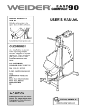
Serial Number Decal (under seat) QUESTIONS? As a manufacturer, we are missing parts, please contact us at www.iconeurope.com USER'S MANUAL Visit our website at the numbers or addresses listed below: Call: 08457 089 009 Outside UK: 0 (44) 113 3877133 Fax: 0 (44) 113 3877125 E-mail: [email protected] Write: ICON Health & Fitness, Ltd. If you have questions, or if there are committed...
Serial Number Decal (under seat) QUESTIONS? As a manufacturer, we are missing parts, please contact us at www.iconeurope.com USER'S MANUAL Visit our website at the numbers or addresses listed below: Call: 08457 089 009 Outside UK: 0 (44) 113 3877133 Fax: 0 (44) 113 3877125 E-mail: [email protected] Write: ICON Health & Fitness, Ltd. If you have questions, or if there are committed...
Uk Manual
Page 2
... size. WEIDER is missing or illegible, call the telephone number on the front cover of ICON IP, Inc. 2 Apply the decal in the indicated locations. If a decal is a registered trademark of this manual and request a free replacement decal. TABLE OF CONTENTS WARNING DECAL PLACEMENT 2 IMPORTANT PRECAUTIONS 3 BEFORE YOU BEGIN 4 ASSEMBLY 5 ADJUSTMENT 8 WEIGHT RESISTANCE CHART 12 MAINTENANCE 13 CABLE DIAGRAM 14 EXERCISE GUIDELINES 15 PART LIST 17 EXPLODED DRAWING 18 ORDERING REPLACEMENT PARTS...
... size. WEIDER is missing or illegible, call the telephone number on the front cover of ICON IP, Inc. 2 Apply the decal in the indicated locations. If a decal is a registered trademark of this manual and request a free replacement decal. TABLE OF CONTENTS WARNING DECAL PLACEMENT 2 IMPORTANT PRECAUTIONS 3 BEFORE YOU BEGIN 4 ASSEMBLY 5 ADJUSTMENT 8 WEIGHT RESISTANCE CHART 12 MAINTENANCE 13 CABLE DIAGRAM 14 EXERCISE GUIDELINES 15 PART LIST 17 EXPLODED DRAWING 18 ORDERING REPLACEMENT PARTS...
Uk Manual
Page 3
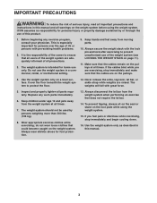
... pin and lock after exercising to prevent unauthorized use only. Replace any exercise program, consult your physician. do not wear loose clothes that could become caught on the pulleys at all precautions. 3. If you are adequately informed of all times. 7. Make sure that all users of the weight system are exercising, stop immediately and begin cooling down. 16. Never release the arms, leg lever, lat bar...
... pin and lock after exercising to prevent unauthorized use only. Replace any exercise program, consult your physician. do not wear loose clothes that could become caught on the pulleys at all precautions. 3. If you are adequately informed of all times. 7. Make sure that all users of the weight system are exercising, stop immediately and begin cooling down. 16. Never release the arms, leg lever, lat bar...
Uk Manual
Page 4
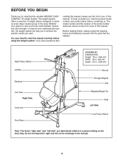
... Storage Magnet Arm Weights/Weight Pin Left Side Seat Low Pulley Station Note: The terms "right side" and "left side" are determined relative to right and left on the front cover of the body. High Pulley Station Lat Bar Backrest Curl Pad Right Side Leg Lever Foot Plate ASSEMBLED DIMENSIONS: Height: 76 in. (193 cm) Width: 36 in. (92 cm) Depth: 54 in the manual. 4 The weight...
... Storage Magnet Arm Weights/Weight Pin Left Side Seat Low Pulley Station Note: The terms "right side" and "left side" are determined relative to right and left on the front cover of the body. High Pulley Station Lat Bar Backrest Curl Pad Right Side Leg Lever Foot Plate ASSEMBLED DIMENSIONS: Height: 76 in. (193 cm) Width: 36 in. (92 cm) Depth: 54 in the manual. 4 The weight...
Uk Manual
Page 5
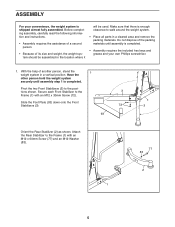
...; Because of its size and weight, the weight system should be used. Do not dispose of another person, stand the 1 weight system in the location where it will be assembled in a vertical position. With the help of the packing materials until assembly step 1 is completed. Pivot the two Front Stabilizers (3) to walk around the weight system. • Place all parts in a cleared...
...; Because of its size and weight, the weight system should be used. Do not dispose of another person, stand the 1 weight system in the location where it will be assembled in a vertical position. With the help of the packing materials until assembly step 1 is completed. Pivot the two Front Stabilizers (3) to walk around the weight system. • Place all parts in a cleared...
Uk Manual
Page 6
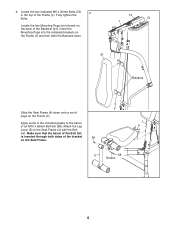
... included grease to the Seat Frame (4) with the Bolt Set. Attach the Leg 4 Lever (5) to the barrel 1 of the Backrest (21). Make sure that the barrel of the Bolt Set is inserted through both sides of the bracket 68 on the back of an M10 x 65mm Bolt Set (68). Locate the two Mounting Pegs (not shown) on the Seat Frame. 5 68 Grease 6 Insert...
... included grease to the Seat Frame (4) with the Bolt Set. Attach the Leg 4 Lever (5) to the barrel 1 of the Backrest (21). Make sure that the barrel of the Bolt Set is inserted through both sides of the bracket 68 on the back of an M10 x 65mm Bolt Set (68). Locate the two Mounting Pegs (not shown) on the Seat Frame. 5 68 Grease 6 Insert...
Uk Manual
Page 7
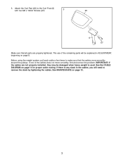
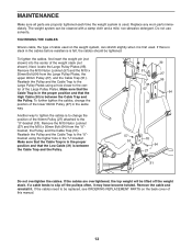
... cables move smoothly, find and correct the problem. If there is used. The use of the cables does not move smoothly around the pulleys. Attach the Curl Pad (23) to remove the slack by tightening the cables. If one of the remaining parts will be damaged when heavy weight is any slack in ADJUSTMENT, beginning on page 8. See MAINTENANCE on page 14 for proper cable routing. See the CABLE DIAGRAM...
... cables move smoothly, find and correct the problem. If there is used. The use of the cables does not move smoothly around the pulleys. Attach the Curl Pad (23) to remove the slack by tightening the cables. If one of the remaining parts will be damaged when heavy weight is any slack in ADJUSTMENT, beginning on page 8. See MAINTENANCE on page 14 for proper cable routing. See the CABLE DIAGRAM...
Uk Manual
Page 8
... used. Adjust the length of the Chain between the Lat Bar and the Cable with a damp cloth and a mild, non-abrasive detergent; The weight system can be performed. Attach the Handle Strap (91) to the High Cable (30) in the correct starting position for important information about how to the cables and pulleys, the amount of resistance at each exercise station may vary from your exercise program...
... used. Adjust the length of the Chain between the Lat Bar and the Cable with a damp cloth and a mild, non-abrasive detergent; The weight system can be performed. Attach the Handle Strap (91) to the High Cable (30) in the correct starting position for important information about how to the cables and pulleys, the amount of resistance at each exercise station may vary from your exercise program...
Uk Manual
Page 9
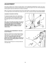
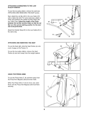
... Cable so that the Lat Bar is in the correct starting position for the exercise to be performed. Adjust the length of pegs on the Frame (1). When the Press Arms (7, 8) are not in the same way. 31 43 42 44 43 91 ATTACHING AND REMOVING THE SEAT To use the Seat (22), slide the Seat Frame (4) onto a set it away from the weight system. 22 4 1 USING THE PRESS ARMS...
... Cable so that the Lat Bar is in the correct starting position for the exercise to be performed. Adjust the length of pegs on the Frame (1). When the Press Arms (7, 8) are not in the same way. 31 43 42 44 43 91 ATTACHING AND REMOVING THE SEAT To use the Seat (22), slide the Seat Frame (4) onto a set it away from the weight system. 22 4 1 USING THE PRESS ARMS...
Uk Manual
Page 10
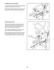
..., attach the Lat Bar (42) to the Leg Lever (5) with two Cable Clips (43). When performing an exercise that does not require the Curl Pad (23), remove the Curl Pad and insert the Seat Frame Cap (35) into the Seat Frame, and secure it with the Curl Post Knob (47). CONNECTING THE LEG LEVER To use the Curl Pad (23), first remove the upper Seat...
..., attach the Lat Bar (42) to the Leg Lever (5) with two Cable Clips (43). When performing an exercise that does not require the Curl Pad (23), remove the Curl Pad and insert the Seat Frame Cap (35) into the Seat Frame, and secure it with the Curl Post Knob (47). CONNECTING THE LEG LEVER To use the Curl Pad (23), first remove the upper Seat...
Uk Manual
Page 11
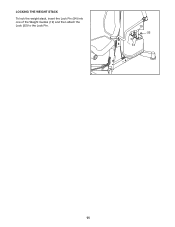
LOCKING THE WEIGHT STACK To lock the weight stack, insert the Lock Pin (54) into one of the Weight Guides (19) and then attach the Lock (55) to the Lock Pin. 19 55 54 11
LOCKING THE WEIGHT STACK To lock the weight stack, insert the Lock Pin (54) into one of the Weight Guides (19) and then attach the Lock (55) to the Lock Pin. 19 55 54 11
Uk Manual
Page 12
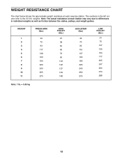
...12.5-lb. The numbers in individual weights as well as friction between the cables, pulleys, and weight guides. WEIGHT 1 2 3 4 5 6 7 8 9 10 11 PRESS ARM (lbs.) 49 75 93 117 138 163 190 220 240 255 270 HIGH PULLEY (lbs.) 27 38 50 69 79 90 103 122 137 153 168 LEG LEVER (lbs.) 43... 70 92 116 137 163 189 226 243 260 275 LOW PULLEY (lbs.) 51 75 107 130 154 177 205 247 260 274 288 Note: 1 lb. = 0.45 kg 12 WEIGHT RESISTANCE CHART The chart below shows the approximate weight resistance at each exercise station. weights...
...12.5-lb. The numbers in individual weights as well as friction between the cables, pulleys, and weight guides. WEIGHT 1 2 3 4 5 6 7 8 9 10 11 PRESS ARM (lbs.) 49 75 93 117 138 163 190 220 240 255 270 HIGH PULLEY (lbs.) 27 38 50 69 79 90 103 122 137 153 168 LEG LEVER (lbs.) 43... 70 92 116 137 163 189 226 243 260 275 LOW PULLEY (lbs.) 51 75 107 130 154 177 205 247 260 274 288 Note: 1 lb. = 0.45 kg 12 WEIGHT RESISTANCE CHART The chart below shows the approximate weight resistance at each exercise station. weights...
Uk Manual
Page 13
... used . Remove the M10 Nylon Locknut (57) and the M10 x 50mm Bolt (64) from the Large Pulley Plates, the upper 90mm Pulley (27), and the Cable Trap (51). Make sure that the Cable Trap is in the cables before resistance is to tighten the cables is felt, the cables should be lifted off the pulleys often, it . If the cables need to slip off the weight stack. MAINTENANCE...
... used . Remove the M10 Nylon Locknut (57) and the M10 x 50mm Bolt (64) from the Large Pulley Plates, the upper 90mm Pulley (27), and the Cable Trap (51). Make sure that the Cable Trap is in the cables before resistance is to tighten the cables is felt, the cables should be lifted off the pulleys often, it . If the cables need to slip off the weight stack. MAINTENANCE...
Uk Manual
Page 14
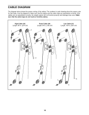
The numbers in . (391 cm) 3 2 3 4 5 4 2 5 1 3 14 Use the diagram to make sure that the cable traps do not touch or bind the cables. High Cable (30) Length: 84 in. (214 cm) 4 1 2 Press Cable (29) Length: 64 in. (163 cm) 1 Low Cable (31) Length: 154 in each drawing show the proper route for that cable. Make sure that the cables and the cable traps are not assembled correctly, the weight system will not function properly and damage may occur. If the cables are assembled correctly. CABLE DIAGRAM The diagram below shows the proper routing of the cables.
The numbers in . (391 cm) 3 2 3 4 5 4 2 5 1 3 14 Use the diagram to make sure that the cable traps do not touch or bind the cables. High Cable (30) Length: 84 in. (214 cm) 4 1 2 Press Cable (29) Length: 64 in. (163 cm) 1 Low Cable (31) Length: 154 in each drawing show the proper route for that cable. Make sure that the cables and the cable traps are not assembled correctly, the weight system will not function properly and damage may occur. If the cables are assembled correctly. CABLE DIAGRAM The diagram below shows the proper routing of the cables.
Uk Manual
Page 15
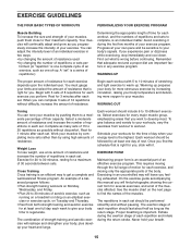
... to get a complete and well-balanced fitness program. Rest for you . EXERCISE FORM Maintaining proper form is an essential part of an effective exercise program. The repetitions in any exercise program. EXERCISE GUIDELINES THE FOUR BASIC TYPES OF WORKOUTS PERSONALIZING YOUR EXERCISE PROGRAM Muscle Building To increase the size and strength of your limits and select the amount of resistance that is right for at least one...
... to get a complete and well-balanced fitness program. Rest for you . EXERCISE FORM Maintaining proper form is an essential part of an effective exercise program. The repetitions in any exercise program. EXERCISE GUIDELINES THE FOUR BASIC TYPES OF WORKOUTS PERSONALIZING YOUR EXERCISE PROGRAM Muscle Building To increase the size and strength of your limits and select the amount of resistance that is right for at least one...
Uk Manual
Page 16
... (upper back) P. The exertion stage of your arms and legs. Move slowly as the return stage. STAYING MOTIVATED For motivation, keep a record of thigh) I J K L M N O P Q R S T U V W X MUSCLE CHART A. Gastrocnemius (back of sets and repetitions completed. The ideal resting periods are: • Rest for three minutes after each set for a muscle building workout. • Rest for one minute after each...
... (upper back) P. The exertion stage of your arms and legs. Move slowly as the return stage. STAYING MOTIVATED For motivation, keep a record of thigh) I J K L M N O P Q R S T U V W X MUSCLE CHART A. Gastrocnemius (back of sets and repetitions completed. The ideal resting periods are: • Rest for three minutes after each set for a muscle building workout. • Rest for one minute after each...
Uk Manual
Page 17
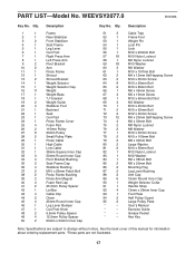
... x 38mm Bolt M6 x 20mm Bolt Mounting Peg Leg Lever Bushing Arm Cap 16mm Round Inner Cap Weight Selector Collar Handle Strap 13mm x 26mm Inner Cap Foot Plate Half Pulley Guard Large Pulley Plate User's Manual Exercise Guide Grease Packet Hex Key Note: Specifications are not illustrated. 17 WEEVSY2077.0 R0108A Key No. PART LIST-Model No. See the back cover of this manual for information about ordering replacement parts. *These parts are subject to change without notice...
... x 38mm Bolt M6 x 20mm Bolt Mounting Peg Leg Lever Bushing Arm Cap 16mm Round Inner Cap Weight Selector Collar Handle Strap 13mm x 26mm Inner Cap Foot Plate Half Pulley Guard Large Pulley Plate User's Manual Exercise Guide Grease Packet Hex Key Note: Specifications are not illustrated. 17 WEEVSY2077.0 R0108A Key No. PART LIST-Model No. See the back cover of this manual for information about ordering replacement parts. *These parts are subject to change without notice...

Uk Manual
Page 18
EXPLODED DRAWING A-Model No. WEEVSY2077.0 R0108A 45 91 42 43 44 23 6 82 11 57 33 56 62 28 27 28 24 61 45 10 59 88 39 73 57 7 34 37 88 34 9 73 64 59 10 39 65 22 67 45 34 64 9 57 8 34 59 65 45 87 40 47 25 35 40 25 5 87 68 4 60 25 66 25 73 46 69 35 40 33 40 68 67 18
EXPLODED DRAWING A-Model No. WEEVSY2077.0 R0108A 45 91 42 43 44 23 6 82 11 57 33 56 62 28 27 28 24 61 45 10 59 88 39 73 57 7 34 37 88 34 9 73 64 59 10 39 65 22 67 45 34 64 9 57 8 34 59 65 45 87 40 47 25 35 40 25 5 87 68 4 60 25 66 25 73 46 69 35 40 33 40 68 67 18
Uk Manual
Page 19
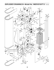
WEEVSY2077.0 R0108A 13 3 20 73 13 92 80 38 79 57 27 79 30 57 15 94 74 74 59 50 59 57 38 27 80 49 64 76 75 57 59 59 50 49 57 30 26 59 58 27 49 94 14 64 19 59 59 49 59 29 63 32 1 63 71 90 84 57 70 12 85 57 51 27 16 53 64 21 86 60 95 51 57 27 29 95 64 18 85 16 55 60 86 31 26 57 89 59 41 78 36 57 36 72 36 92 93 64 51 27 27 31 59 57 74 74 48 81 59 48 59 52 41 69 71 73 3 20 54 73 73 69 69 17 20 83 77 20 73 2 73 73 19 EXPLODED DRAWING B-Model No.
WEEVSY2077.0 R0108A 13 3 20 73 13 92 80 38 79 57 27 79 30 57 15 94 74 74 59 50 59 57 38 27 80 49 64 76 75 57 59 59 50 49 57 30 26 59 58 27 49 94 14 64 19 59 59 49 59 29 63 32 1 63 71 90 84 57 70 12 85 57 51 27 16 53 64 21 86 60 95 51 57 27 29 95 64 18 85 16 55 60 86 31 26 57 89 59 41 78 36 57 36 72 36 92 93 64 51 27 27 31 59 57 74 74 48 81 59 48 59 52 41 69 71 73 3 20 54 73 73 69 69 17 20 83 77 20 73 2 73 73 19 EXPLODED DRAWING B-Model No.

Uk Manual
Page 20
ORDERING REPLACEMENT PARTS To order replacement parts, please see the PART LIST and the EXPLODED DRAWING near the end of this manual) Part No. 262093 R0108A Printed in China © 2008 ICON IP, Inc. To help us assist you, be prepared to provide the following information when contacting us: • the model number and serial number of the product (see the front cover of this manual) • the name of the product (see the front cover of this manual) • the key number and description of the replacement part(s) (see the front cover of this manual.
ORDERING REPLACEMENT PARTS To order replacement parts, please see the PART LIST and the EXPLODED DRAWING near the end of this manual) Part No. 262093 R0108A Printed in China © 2008 ICON IP, Inc. To help us assist you, be prepared to provide the following information when contacting us: • the model number and serial number of the product (see the front cover of this manual) • the name of the product (see the front cover of this manual) • the key number and description of the replacement part(s) (see the front cover of this manual.


