
Owners Manual
Page 1
MRF-350 Installation Manual Optimizing Narrow Band Reception with the RFX-250 and MSC System Remotes
MRF-350 Installation Manual Optimizing Narrow Band Reception with the RFX-250 and MSC System Remotes

Owners Manual
Page 2
... notice. MRF-350 Installation Manual ©2006 - 2013 Universal Remote Control, Inc. No part of their respective companies or organizations. UNIVERSAL REMOTE CONTROL, INC. SHALL NOT BE LIABLE FOR OPERATIONAL, TECHNICAL OR EDITORIAL ERRORS/OMISSIONS MADE IN THIS MANUAL. The information in this owner's manual may be subject to change without prior written consent from Universal Remote Control, Inc. Complete Control is copyright protected. The information in this owner's manual is a registered trademark of Universal Remote Control, Inc...
... notice. MRF-350 Installation Manual ©2006 - 2013 Universal Remote Control, Inc. No part of their respective companies or organizations. UNIVERSAL REMOTE CONTROL, INC. SHALL NOT BE LIABLE FOR OPERATIONAL, TECHNICAL OR EDITORIAL ERRORS/OMISSIONS MADE IN THIS MANUAL. The information in this owner's manual may be subject to change without prior written consent from Universal Remote Control, Inc. Complete Control is copyright protected. The information in this owner's manual is a registered trademark of Universal Remote Control, Inc...

Owners Manual
Page 3
Step by Step via PC 7 Controlling An Array of Identical Components or Zones 8 Identical Components/Zone - Step by Step via PC 8 Programming For Multiple Equipment Locations 11 Frequently Asked Questions 12 Warranty 12 Limited Warranty Statement 13 End User Agreement 15 Specifications 15 TABLE OF CONTENTS Introduction 1 Features and Benefits 2 Parts Guide 2 Optimizing Range and Reliability 3 Connecting IR and Setting Output Levels 6 Front Blaster Overload 7 Disabling the Front Blaster -
Step by Step via PC 7 Controlling An Array of Identical Components or Zones 8 Identical Components/Zone - Step by Step via PC 8 Programming For Multiple Equipment Locations 11 Frequently Asked Questions 12 Warranty 12 Limited Warranty Statement 13 End User Agreement 15 Specifications 15 TABLE OF CONTENTS Introduction 1 Features and Benefits 2 Parts Guide 2 Optimizing Range and Reliability 3 Connecting IR and Setting Output Levels 6 Front Blaster Overload 7 Disabling the Front Blaster -
Owners Manual
Page 4
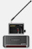
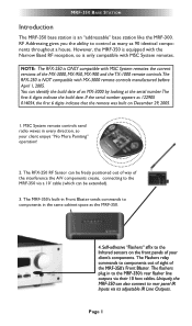
... to control as many as the MRF-350. However, the MRF-350 is equipped with MSC System remotes. 1. The MRF-350's built-in every direction, so your client enjoys "No More Pointing" operation! 2. MSC System remote controls send radio waves in Front Blaster sends commands to the MRF-350 via a 10' cable (which can be extended). 3. MRF-350 BASE STATION Introduction The MRF-350 base station is only compatible with the Narrow Band RF...
... to control as many as the MRF-350. However, the MRF-350 is equipped with MSC System remotes. 1. The MRF-350's built-in every direction, so your client enjoys "No More Pointing" operation! 2. MSC System remote controls send radio waves in Front Blaster sends commands to the MRF-350 via a 10' cable (which can be extended). 3. MRF-350 BASE STATION Introduction The MRF-350 base station is only compatible with the Narrow Band RF...

Owners Manual
Page 5
... that is designed to be programmed to specifically control components in the Den, the MX series remote only sends commands to three RFX-250 RF Sensors connected in one MRF-350 or route volume commands for Keypads or IR Repeater Systems The MRF-350 rear panel IR input will directly power some brands and models of keypad directly. Parts Guide The MRF-350 RF Base Station includes: 1 - Up To Fifteen...
... that is designed to be programmed to specifically control components in the Den, the MX series remote only sends commands to three RFX-250 RF Sensors connected in one MRF-350 or route volume commands for Keypads or IR Repeater Systems The MRF-350 rear panel IR input will directly power some brands and models of keypad directly. Parts Guide The MRF-350 RF Base Station includes: 1 - Up To Fifteen...
Owners Manual
Page 6
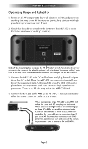
... devices with tinned ends. Connect the MRF-350 to the MRF-350's RF INPUT. Connect the RFX-250 to its DC wall adapter and plug the wall adapter into a live AC outlet. You can connect to either the screw connector or the jack as 200', then connected to 0. 3. Page 3 MRF-350 BASE STATION Optimizing Range and Reliability 1. Slide off the mounting plate to 50% and power on anything that the...
... devices with tinned ends. Connect the MRF-350 to the MRF-350's RF INPUT. Connect the RFX-250 to its DC wall adapter and plug the wall adapter into a live AC outlet. You can connect to either the screw connector or the jack as 200', then connected to 0. 3. Page 3 MRF-350 BASE STATION Optimizing Range and Reliability 1. Slide off the mounting plate to 50% and power on anything that the...
Owners Manual
Page 7
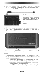
... the wire. If no buttons are pressed on any choice and you have three last resort options: a. If you must relocate the RFX-250 to a new location. Page 4 MRF-350 BASE STATION 5. Cup your installation location simply doesn't offer you any remote control, no valid RF transmissions are detecting interference everywhere you place the RFX-250 you are being received...
... the wire. If no buttons are pressed on any choice and you have three last resort options: a. If you must relocate the RFX-250 to a new location. Page 4 MRF-350 BASE STATION 5. Cup your installation location simply doesn't offer you any remote control, no valid RF transmissions are detecting interference everywhere you place the RFX-250 you are being received...
Owners Manual
Page 8
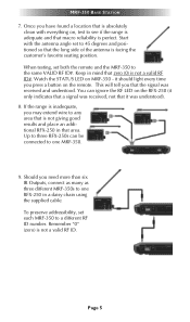
...-250 in a daisy chain using the supplied cable. You can be connected to see if the range is adequate and that macro reliability is perfect. If the range is inadequate, you may extend wire to 45 degrees and positioned so that the long side of the antenna is not giving good results ... indicates that a signal was received, not that it should light every time you have found a location that is absolutely clean with the antenna angle set to any area that zero (0) is not a valid RF ID. This will tell you need more than six IR Outputs, connect as many as three different MRF-350s to the same ...
...-250 in a daisy chain using the supplied cable. You can be connected to see if the range is adequate and that macro reliability is perfect. If the range is inadequate, you may extend wire to 45 degrees and positioned so that the long side of the antenna is not giving good results ... indicates that a signal was received, not that it should light every time you have found a location that is absolutely clean with the antenna angle set to any area that zero (0) is not a valid RF ID. This will tell you need more than six IR Outputs, connect as many as three different MRF-350s to the same ...
Owners Manual
Page 9
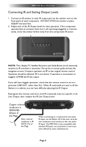
... 6 MRF-350 BASE STATION Connecting IR and Setting Output Levels 1. Connect an IR emitter to each IR output and run the emitter wire to the front panel of each of the Plug). The MRF-350 is inconsistent or sluggish, LOWER the IR line output. If operation is only compatible with standard IR Inputs, not proprietary control systems offered by some manufacturers. NOTE: TiVo, Replay TV, Satellite Receivers and Cable...
... 6 MRF-350 BASE STATION Connecting IR and Setting Output Levels 1. Connect an IR emitter to each IR output and run the emitter wire to the front panel of each of the Plug). The MRF-350 is inconsistent or sluggish, LOWER the IR line output. If operation is only compatible with standard IR Inputs, not proprietary control systems offered by some manufacturers. NOTE: TiVo, Replay TV, Satellite Receivers and Cable...
Owners Manual
Page 10
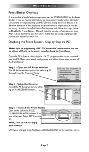
... the Program Menu. SAVE your saved configuration and follow the steps below to apply your MRF-350 can purchase an additional MRF-350. If you can control to the remote control. Open your changes using File|Save and DOWNLOAD to six. A list box will limit the number of audio/video components can be necessary to utilize the self-adhesive flashers only and follow these steps to turn...
... the Program Menu. SAVE your saved configuration and follow the steps below to apply your MRF-350 can purchase an additional MRF-350. If you can control to the remote control. Open your changes using File|Save and DOWNLOAD to six. A list box will limit the number of audio/video components can be necessary to utilize the self-adhesive flashers only and follow these steps to turn...
Owners Manual
Page 11
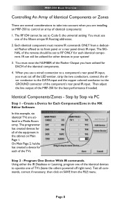
... Flasher Output you must use a wired connection to a component's rear panel IR input, you have utilized for EACH of the remote should be set to the GROUND connector of TV's (leave the others powered off right now). The RF ID# cannot be set to control an array of the TVs. The SIGNAL of the identical components. 4. Then adjust the line output of the MRF-350 for...
... Flasher Output you must use a wired connection to a component's rear panel IR input, you have utilized for EACH of the remote should be set to the GROUND connector of TV's (leave the others powered off right now). The RF ID# cannot be set to control an array of the TVs. The SIGNAL of the identical components. 4. Then adjust the line output of the MRF-350 for...
Owners Manual
Page 12
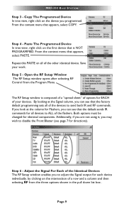
... be changed for directions). From the context menu that appears, select PASTE. Repeat this PASTE on the first device that the factory default programming sets all of the Identical Devices The RF Setup window enables you may wish to disable the Front Blaster (see page 7 for identical components. From the context menu that appears, select COPY. MRF-350 BASE STATION Step 3 - The RF Setup window...
... be changed for directions). From the context menu that appears, select PASTE. Repeat this PASTE on the first device that the factory default programming sets all of the Identical Devices The RF Setup window enables you may wish to disable the Front Blaster (see page 7 for identical components. From the context menu that appears, select COPY. MRF-350 BASE STATION Step 3 - The RF Setup window...
Owners Manual
Page 13
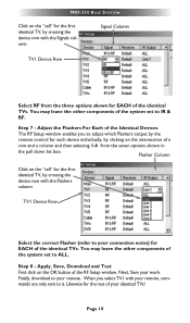
... (refer to your remote, commands are only sent to adjust which Flashers output by the remote control for EACH of your work. Likewise for EACH of the system set to your remote. Step 7 - Step 8 - Next, Save your identical TVs! Finally, download to IR & RF. You may leave the other components of the identical TVs. MRF-350 BASE STATION Click on the "cell...
... (refer to your remote, commands are only sent to adjust which Flashers output by the remote control for EACH of your work. Likewise for EACH of the system set to your remote. Step 7 - Step 8 - Next, Save your identical TVs! Finally, download to IR & RF. You may leave the other components of the identical TVs. MRF-350 BASE STATION Click on the "cell...
Owners Manual
Page 14
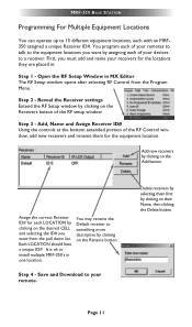
... the Program Menu. Step 2 - Add new receivers by clicking on their Name, then clicking the Delete button. Save and Download to install multiple MRF-350's in : Step 1 - Page 11 You program each LOCATION by clicking on the Rename button. Reveal the Receiver settings Extend the RF Setup window by assigning each with an MRF350 assigned a unique Receiver ID#. Each LOCATION should have a unique ID#. MRF-350 BASE STATION Programming For...
... the Program Menu. Step 2 - Add new receivers by clicking on their Name, then clicking the Delete button. Save and Download to install multiple MRF-350's in : Step 1 - Page 11 You program each LOCATION by clicking on the Rename button. Reveal the Receiver settings Extend the RF Setup window by assigning each with an MRF350 assigned a unique Receiver ID#. Each LOCATION should have a unique ID#. MRF-350 BASE STATION Programming For...
Owners Manual
Page 15
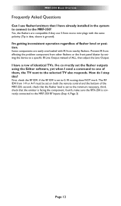
...set to the MRF-350 RF Inputs (Step 4, Page 3) Page 12 The RF ID# from 1-9 or A-F must be set to a specific IR Line Output instead of flasher level or position. I have already installed in the system to connect to the selected TV also responds. Prevent IR from affecting the problem...polarity (Tip is data, sleeve is set on both the remote control and the bottom of them, the TV next to the MRF-350? I 'm getting inconsistent operation regardless of ALL, then adjust the Line Output. MRF-350 BASE STATION Frequently Asked Questions Can I use 3.5mm mono mini plugs with IR from ...
...set to the MRF-350 RF Inputs (Step 4, Page 3) Page 12 The RF ID# from 1-9 or A-F must be set to a specific IR Line Output instead of flasher level or position. I have already installed in the system to connect to the selected TV also responds. Prevent IR from affecting the problem...polarity (Tip is data, sleeve is set on both the remote control and the bottom of them, the TV next to the MRF-350? I 'm getting inconsistent operation regardless of ALL, then adjust the Line Output. MRF-350 BASE STATION Frequently Asked Questions Can I use 3.5mm mono mini plugs with IR from ...

Owners Manual
Page 16
... OPERATIONAL, TECHNICAL OR EDITORIAL ERRORS AND/OR OMISSIONS MADE IN THE URC DOCUMENTATION. Limited Warranty and Disclaimers Universal Remote Control, Inc. ("URC") warrants that the URC equipment and/or the URC software fails to so comply, URC shall, at its own expense, take all reasonable measures to promptly cause such to its functional specifications at the time of purchase the URC...
... OPERATIONAL, TECHNICAL OR EDITORIAL ERRORS AND/OR OMISSIONS MADE IN THE URC DOCUMENTATION. Limited Warranty and Disclaimers Universal Remote Control, Inc. ("URC") warrants that the URC equipment and/or the URC software fails to so comply, URC shall, at its own expense, take all reasonable measures to promptly cause such to its functional specifications at the time of purchase the URC...
Owners Manual
Page 17
... the URC equipment support and other verifiable proof of our Total Control® whole-house equipment are the end user's exclusive remedies. Buying URC's PC programmable remotes or any of any part of a defect, these are authorized for online internet sales. To obtain an RGA number, you must deliver the URC equipment, freight prepaid, in material or workmanship during service and URC...
... the URC equipment support and other verifiable proof of our Total Control® whole-house equipment are the end user's exclusive remedies. Buying URC's PC programmable remotes or any of any part of a defect, these are authorized for online internet sales. To obtain an RGA number, you must deliver the URC equipment, freight prepaid, in material or workmanship during service and URC...
Owners Manual
Page 18
... EVENT SHALL URC BE LIABLE FOR LOSS OF OR DAMAGE TO DATA, COMPUTER SYSTEMS OR COMPUTER PROGRAMS. URC'S LIABILITY, IF ANY, FOR DIRECT DAMAGES OF ANY FORM SHALL BE LIMITED TO ACTUAL DAMAGES, NOT IN EXCESS OF AMOUNTS PAID BY END USER FOR THE URC EQUIPMENT. Specifications Power Supply: 9V 300mA IR Flasher Line Outputs: 3.5mm Mono Mini Jack RF Frequency: 418MHz Size: 8" x 3.5" x 1.25...
... EVENT SHALL URC BE LIABLE FOR LOSS OF OR DAMAGE TO DATA, COMPUTER SYSTEMS OR COMPUTER PROGRAMS. URC'S LIABILITY, IF ANY, FOR DIRECT DAMAGES OF ANY FORM SHALL BE LIMITED TO ACTUAL DAMAGES, NOT IN EXCESS OF AMOUNTS PAID BY END USER FOR THE URC EQUIPMENT. Specifications Power Supply: 9V 300mA IR Flasher Line Outputs: 3.5mm Mono Mini Jack RF Frequency: 418MHz Size: 8" x 3.5" x 1.25...

Owners Manual
Page 20
... not installed and used in a residential installation. However, there is encouraged to try to correct the interference by one more of the FCC Rules. Such modifications could void the user's authority to operate the equipment. Information To The User This equipment has been tested and found to comply with the instructions, may cause harmful interference to radio communications. Warning Changes...
... not installed and used in a residential installation. However, there is encouraged to try to correct the interference by one more of the FCC Rules. Such modifications could void the user's authority to operate the equipment. Information To The User This equipment has been tested and found to comply with the instructions, may cause harmful interference to radio communications. Warning Changes...

