
Maintenance Manual
Page 2
... death or serious bodily injury if the safety instruction is a registered trademark of the information contained herein. The procedures described in this manual are registered trademarks of Toshiba. ii Tecra A3/S2 Maintenance Manual Microsoft, MS-DOS, Windows, DirectSound and DirectMusic are intended to your attention. Sound Blaster is a trademark of Creative Technology Ltd. Photo...
... death or serious bodily injury if the safety instruction is a registered trademark of the information contained herein. The procedures described in this manual are registered trademarks of Toshiba. ii Tecra A3/S2 Maintenance Manual Microsoft, MS-DOS, Windows, DirectSound and DirectMusic are intended to your attention. Sound Blaster is a trademark of Creative Technology Ltd. Photo...
Maintenance Manual
Page 3
.... Toshiba requires service technicians and authorized dealers or service providers to ensure the following safety precautions are adhered to fasten screws securely with the right screwdriver. If a screw is not fully fastened, it could come loose, creating a danger of the wrong battery can cause the battery to explode. Tecra A3/S2 Maintenance Manual iii... to your safe maintenance service. NOTE Note" contains general information that relates to use only the same model battery or an equivalent battery recommended by Toshiba.
.... Toshiba requires service technicians and authorized dealers or service providers to ensure the following safety precautions are adhered to fasten screws securely with the right screwdriver. If a screw is not fully fastened, it could come loose, creating a danger of the wrong battery can cause the battery to explode. Tecra A3/S2 Maintenance Manual iii... to your safe maintenance service. NOTE Note" contains general information that relates to use only the same model battery or an equivalent battery recommended by Toshiba.
Maintenance Manual
Page 4
... Pin assignments Keyboard scan/character codes Key layout Screw torque list Reliability iv Tecra A3/S2 Maintenance Manual Chapter 4 ...Replacement Procedures describes the removal and replacement of the FRUs. Appendices ...The appendices describe the following parts: Chapter 1 ...Hardware Overview describes the Tecra A3/S2 Series system unit and each FRU. Chapter 2 ...Troubleshooting Procedures explains how...
... Pin assignments Keyboard scan/character codes Key layout Screw torque list Reliability iv Tecra A3/S2 Maintenance Manual Chapter 4 ...Replacement Procedures describes the removal and replacement of the FRUs. Appendices ...The appendices describe the following parts: Chapter 1 ...Hardware Overview describes the Tecra A3/S2 Series system unit and each FRU. Chapter 2 ...Troubleshooting Procedures explains how...
Maintenance Manual
Page 5
... following their definition. The key top symbol as it appears on its display is presented in the boldface type below : Format complete System transferred Tecra A3/S2 Maintenance Manual v We identify such operations by the key top symbols separated by the computer that you must hold down Ctrl and at the same time...
... following their definition. The key top symbol as it appears on its display is presented in the boldface type below : Format complete System transferred Tecra A3/S2 Maintenance Manual v We identify such operations by the key top symbols separated by the computer that you must hold down Ctrl and at the same time...

Maintenance Manual
Page 6
... 2-23 2.10 Speaker Troubleshooting 2-25 2.11 Modem Troubleshooting 2-27 2.12 PCMCIA Troubleshooting 2-29 2.13 IEEE 1394 Troubleshooting 2-31 2.14 Wireless LAN Troubleshooting 2-33 vi Tecra A3/S2 Maintenance Manual Bookmark not defined. 2.4 Display Troubleshooting Error! Table of Contents Chapter 1 Hardware Overview 1.1 Features ...1-1 1.2 System Unit ...1-5 1.3 2.5-inch Hard Disk Drive 1-9 1.4 Removable Drives ...1-10 1.5 Power Supply...
... 2-23 2.10 Speaker Troubleshooting 2-25 2.11 Modem Troubleshooting 2-27 2.12 PCMCIA Troubleshooting 2-29 2.13 IEEE 1394 Troubleshooting 2-31 2.14 Wireless LAN Troubleshooting 2-33 vi Tecra A3/S2 Maintenance Manual Bookmark not defined. 2.4 Display Troubleshooting Error! Table of Contents Chapter 1 Hardware Overview 1.1 Features ...1-1 1.2 System Unit ...1-5 1.3 2.5-inch Hard Disk Drive 1-9 1.4 Removable Drives ...1-10 1.5 Power Supply...
Maintenance Manual
Page 7
Bookmark not defined. 3.5 PIO Loopback Test Error! Bookmark not defined. 3.7 Speaker Audio Test Error! Bookmark not defined. 3.11 CD-ROM Test Error! Tecra A3/S2 Maintenance Manual vii Bookmark not defined. 3.9 Main Battery Charge Test Error! Bookmark not defined. 3.18 RTC Test Error! Bookmark not defined. 3.14 LCD Pixels Mode Test Error! ...
Bookmark not defined. 3.5 PIO Loopback Test Error! Bookmark not defined. 3.7 Speaker Audio Test Error! Bookmark not defined. 3.11 CD-ROM Test Error! Tecra A3/S2 Maintenance Manual vii Bookmark not defined. 3.9 Main Battery Charge Test Error! Bookmark not defined. 3.18 RTC Test Error! Bookmark not defined. 3.14 LCD Pixels Mode Test Error! ...
Maintenance Manual
Page 8
Chapter 4 Replacement Procedures 4.1 General ...4-1 4.2 Battery ...4-7 4.3 PC Card ...4-8 4.4 HDD ...4-9 4.5 Optical Drive Module...4-12 4.6 Optical Drive ...4-13 4.7 Wireless LAN...4-15 4.8 Expansion Memory ...4-17 4.9 Keyboard ...4-21 4.10 Bluetooth ...4-21 4.11 Modem...4-25 4.12 Display Assembly...4-26 4.13 Top Cover...4-28 4.14 Touch Pad...4-31 4.15 Speakers...4-32 4.16 System Board ...4-33 4.17 Direct Play buttom board 4-36 4.18 Fan, Hest & CPU...4-37 4.19 Display Mask...4-38 4.20 LCD Module...4-42 4.21 FL Inverter Board...4-44 viii Tecra A3/S2 Maintenance Manual
Chapter 4 Replacement Procedures 4.1 General ...4-1 4.2 Battery ...4-7 4.3 PC Card ...4-8 4.4 HDD ...4-9 4.5 Optical Drive Module...4-12 4.6 Optical Drive ...4-13 4.7 Wireless LAN...4-15 4.8 Expansion Memory ...4-17 4.9 Keyboard ...4-21 4.10 Bluetooth ...4-21 4.11 Modem...4-25 4.12 Display Assembly...4-26 4.13 Top Cover...4-28 4.14 Touch Pad...4-31 4.15 Speakers...4-32 4.16 System Board ...4-33 4.17 Direct Play buttom board 4-36 4.18 Fan, Hest & CPU...4-37 4.19 Display Mask...4-38 4.20 LCD Module...4-42 4.21 FL Inverter Board...4-44 viii Tecra A3/S2 Maintenance Manual
Maintenance Manual
Page 9
Appendices Appendix A Handling the LCD Module A-1 Appendix B Board Layout ...B-1 Appendix C Pin Assignments C-1 Appendix D Keyboard Scan/Character Codes D-1 Appendix E Key Layout...E-1 Appendix F Series Screw Torque List F-1 Appendix G Reliability...G-1 Tecra A3/S2 Maintenance Manual ix
Appendices Appendix A Handling the LCD Module A-1 Appendix B Board Layout ...B-1 Appendix C Pin Assignments C-1 Appendix D Keyboard Scan/Character Codes D-1 Appendix E Key Layout...E-1 Appendix F Series Screw Torque List F-1 Appendix G Reliability...G-1 Tecra A3/S2 Maintenance Manual ix

Maintenance Manual
Page 11
1 Hardware Overview 1-ii Tecra A3/S2 Series Maintenance Manual
1 Hardware Overview 1-ii Tecra A3/S2 Series Maintenance Manual

Maintenance Manual
Page 12
Bookmark not defined. 1.4.2 DVD-ROM Drive 1-15 1.4.3 CD-ROM Drive 1-15 1.4.4 DVD±R/±RW Drive 1-15 1.4.5 DVD Super Multi Drive 1-17 1.5 Power Supply ...1-15 1.6 Batteries ...1-21 1.6.1 Main Battery 1-21 1.6.2 RTC battery 1-22 Tecra A3/S2 Series Maintenance Manual 1-iii Chapter 1 Contents 1 Hardware Overview 1.1 Features ...1-5 1.2 System Unit...1-10 1.3 2.5-inch Hard Disk Drive 1-14 1.4 Removable Drives...1-15 1.4.1 DVD-R/-RW Drive Error!
Bookmark not defined. 1.4.2 DVD-ROM Drive 1-15 1.4.3 CD-ROM Drive 1-15 1.4.4 DVD±R/±RW Drive 1-15 1.4.5 DVD Super Multi Drive 1-17 1.5 Power Supply ...1-15 1.6 Batteries ...1-21 1.6.1 Main Battery 1-21 1.6.2 RTC battery 1-22 Tecra A3/S2 Series Maintenance Manual 1-iii Chapter 1 Contents 1 Hardware Overview 1.1 Features ...1-5 1.2 System Unit...1-10 1.3 2.5-inch Hard Disk Drive 1-14 1.4 Removable Drives...1-15 1.4.1 DVD-R/-RW Drive Error!
Maintenance Manual
Page 13
1 Hardware Overview 1-iv Tecra A3/S2 Series Maintenance Manual
1 Hardware Overview 1-iv Tecra A3/S2 Series Maintenance Manual
Maintenance Manual
Page 14
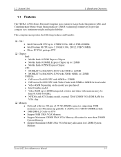
... Maximum 64MB UMA VGA Memory allocation for VGA chip. ‰ Memory • On board with 32MB, 64MB, or 128MB. 1.2 System Unit 1 Hardware Overview 1.1 Features The TECRA A3/S2 Series Personal Computer uses extensive Large Scale Integration (LSI), and Complementary Metal-Oxide Semiconductor (CMOS) technology extensively to 2.13GHz 0.09u, 2M L2, FSB 533MHz... share with main memory for Intel 915GM/ 910GML. • NVIDIA and ATI Graphic model, external 32/64/128MB VGA DDR RAM for 128MB System Memory Tecra A3/S2 Series Maintenance Manual 1-5
... Maximum 64MB UMA VGA Memory allocation for VGA chip. ‰ Memory • On board with 32MB, 64MB, or 128MB. 1.2 System Unit 1 Hardware Overview 1.1 Features The TECRA A3/S2 Series Personal Computer uses extensive Large Scale Integration (LSI), and Complementary Metal-Oxide Semiconductor (CMOS) technology extensively to 2.13GHz 0.09u, 2M L2, FSB 533MHz... share with main memory for Intel 915GM/ 910GML. • NVIDIA and ATI Graphic model, external 32/64/128MB VGA DDR RAM for 128MB System Memory Tecra A3/S2 Series Maintenance Manual 1-5
Maintenance Manual
Page 15
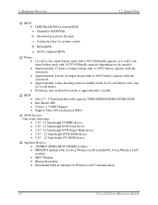
....11a+b+g Wireless LAN module/802.11b+g Wireless LAN module) • MDC Modem • Bluetooth modem • Dual-Band build in Antenna for Wireless LAN Communication. 1-6 Tecra A3/S2 Series Maintenance Manual c) Various hot key for system BIOS.
....11a+b+g Wireless LAN module/802.11b+g Wireless LAN module) • MDC Modem • Bluetooth modem • Dual-Band build in Antenna for Wireless LAN Communication. 1-6 Tecra A3/S2 Series Maintenance Manual c) Various hot key for system BIOS.
Maintenance Manual
Page 16
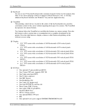
... for volume control • One optional IEEE 1394 port • FIR • One optional 6-in-1 port, support SD/MMC/SM/MS/MS Pro/xD Tecra A3/S2 Series Maintenance Manual 1-7 Two buttons below the TouchPad are using. ‰ Display • 15.0" TFT screen with a resolution of 1600 horizontal x1200 vertical pixels UXGA •...
... for volume control • One optional IEEE 1394 port • FIR • One optional 6-in-1 port, support SD/MMC/SM/MS/MS Pro/xD Tecra A3/S2 Series Maintenance Manual 1-7 Two buttons below the TouchPad are using. ‰ Display • 15.0" TFT screen with a resolution of 1600 horizontal x1200 vertical pixels UXGA •...
Maintenance Manual
Page 17
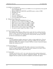
...-equipped devices. 1 Hardware Overview 1.2 System Unit ‰ PCMCIA Card Organization • Accommodate one type II device for TECRA A3 or two type II devices/one type III device for TECRA S2. • SRAM, OTPROM, FLASH ROM, mask ROM memory card up to 512MB ‰ Universal Serial Bus (USB...) The computer comes with three USB ports that comply with stereo speakers and jacks for headphone and external microphone 1-8 Tecra A3/S2 Series Maintenance Manual It is ...
...-equipped devices. 1 Hardware Overview 1.2 System Unit ‰ PCMCIA Card Organization • Accommodate one type II device for TECRA A3 or two type II devices/one type III device for TECRA S2. • SRAM, OTPROM, FLASH ROM, mask ROM memory card up to 512MB ‰ Universal Serial Bus (USB...) The computer comes with three USB ports that comply with stereo speakers and jacks for headphone and external microphone 1-8 Tecra A3/S2 Series Maintenance Manual It is ...
Maintenance Manual
Page 18
... Button You can associate an application to this connector for automatic launch. • TOSHIBA Presentation Button This button allows the user to switch between the LCD and LCD/CRT (or projector). Tecra A3/S2 Series Maintenance Manual 1-9 1.2 System Unit 1 Hardware Overview ‰ TV-out port Plug a 4-pins S-video cable into this button for output...
... Button You can associate an application to this connector for automatic launch. • TOSHIBA Presentation Button This button allows the user to switch between the LCD and LCD/CRT (or projector). Tecra A3/S2 Series Maintenance Manual 1-9 1.2 System Unit 1 Hardware Overview ‰ TV-out port Plug a 4-pins S-video cable into this button for output...
Maintenance Manual
Page 19
...; Memory • On board with LPC Interface • PC99a, PC2001 • ACPI 2.0 Compliant • Serial Ports • One Full Function Serial Port 1-10 Tecra A3/S2 Series Maintenance Manual 1 Hardware Overview 1.2 System Unit 1.2 System Unit The system unit is composed of 200/250/266/333MHZ • 3D Graphics Engine • Analog Display support...
...; Memory • On board with LPC Interface • PC99a, PC2001 • ACPI 2.0 Compliant • Serial Ports • One Full Function Serial Port 1-10 Tecra A3/S2 Series Maintenance Manual 1 Hardware Overview 1.2 System Unit 1.2 System Unit The system unit is composed of 200/250/266/333MHZ • 3D Graphics Engine • Analog Display support...
Maintenance Manual
Page 20
... Inputs. • High quality differential CD Input. • Power Management and enhanced power saving features. • Meets Microsoft® WHQL/WLP2.0 audio Requirements. Tecra A3/S2 Series Maintenance Manual 1-11 1.2 System Unit 1 Hardware Overview • High Speed 16C550A Compatible UARTs with Send/Receive 16-Byte FIFO • Supports 230k and 460k Baud •...
... Inputs. • High quality differential CD Input. • Power Management and enhanced power saving features. • Meets Microsoft® WHQL/WLP2.0 audio Requirements. Tecra A3/S2 Series Maintenance Manual 1-11 1.2 System Unit 1 Hardware Overview • High Speed 16C550A Compatible UARTs with Send/Receive 16-Byte FIFO • Supports 230k and 460k Baud •...
Maintenance Manual
Page 21
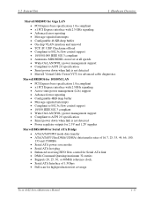
... tolerate large host latency. • Separate cable bias(TPBIAS) for each port. • Register access fail interrupt when the PHY SCLK is not active. 1-12 Tecra A3/S2 Series Maintenance Manual
... tolerate large host latency. • Separate cable bias(TPBIAS) for each port. • Register access fail interrupt when the PHY SCLK is not active. 1-12 Tecra A3/S2 Series Maintenance Manual
Maintenance Manual
Page 22
... 32 entries • Supports 20, 25, 30, or 40MHz reference clock. • Serial ATA Interface of 1.5Gbps • Full scan for high production test coverage Tecra A3/S2 Series Maintenance Manual 1-13
... 32 entries • Supports 20, 25, 30, or 40MHz reference clock. • Serial ATA Interface of 1.5Gbps • Full scan for high production test coverage Tecra A3/S2 Series Maintenance Manual 1-13


