
User Manual
Page 57
..., click Start, Turn off the computer using the Start menu. The Turn off the computer. 3 Unplug and remove any cables connected to the computer. 4 Remove the battery (see "Removing the battery from the computer" on page 120). 5 Close the display panel and turn the computer upside down to locate the expansion memory slot cover to operate the computer with the computer, a beep will be installed in slot B only. If you install or remove a memory module while the...
..., click Start, Turn off the computer using the Start menu. The Turn off the computer. 3 Unplug and remove any cables connected to the computer. 4 Remove the battery (see "Removing the battery from the computer" on page 120). 5 Close the display panel and turn the computer upside down to locate the expansion memory slot cover to operate the computer with the computer, a beep will be installed in slot B only. If you install or remove a memory module while the...
User Manual
Page 177
If you change your system's configuration or verify the startup procedure to fix the problem. The Windows® Advanced Options menu displays these problems, use the options in the Startup menu to fix the problem. To open the Startup menu: 1 Restart your computer. 2 Press F8 when your computer starts. Unless a hardware device has failed, problems usually occur when you experience any of these options: ❖ Safe Mode Using Startup options to fix problems If the operating system fails to start . ❖ The operating system responds...
If you change your system's configuration or verify the startup procedure to fix the problem. The Windows® Advanced Options menu displays these problems, use the options in the Startup menu to fix the problem. To open the Startup menu: 1 Restart your computer. 2 Press F8 when your computer starts. Unless a hardware device has failed, problems usually occur when you experience any of these options: ❖ Safe Mode Using Startup options to fix problems If the operating system fails to start . ❖ The operating system responds...

User Manual
Page 187
... setting. 187 If Something Goes Wrong Resolving a hardware conflict You have a second keyboard, try it works, the first keyboard may have gone into a working . Press any key, type the password and press Enter. Display problems Here are using an external monitor: ❖ Check that the monitor is turned on. ❖ Check that the cable connecting the external monitor to the computer is firmly attached. ❖ Try adjusting the contrast and brightness controls on the external monitor...
... setting. 187 If Something Goes Wrong Resolving a hardware conflict You have a second keyboard, try it works, the first keyboard may have gone into a working . Press any key, type the password and press Enter. Display problems Here are using an external monitor: ❖ Check that the monitor is turned on. ❖ Check that the cable connecting the external monitor to the computer is firmly attached. ❖ Try adjusting the contrast and brightness controls on the external monitor...

User Manual
Page 209
... antenna on-off switch is in the on position.) Fn + This hot key turns the cursor control overlay on and off. Fn + This hot key turns the numeric overlay on and off . Fn + Fn + [Spacebar] This hot key turns the scroll lock feature on page 67. This hot key switches screen or video modes. 209 Hot Keys Disabling or enabling the TouchPad Disabling or enabling the TouchPad Fn + This hot key enables/disables the TouchPad. To use the TouchPad, see "Disabling or enabling the TouchPad" on and...
... antenna on-off switch is in the on position.) Fn + This hot key turns the cursor control overlay on and off. Fn + This hot key turns the numeric overlay on and off . Fn + Fn + [Spacebar] This hot key turns the scroll lock feature on page 67. This hot key switches screen or video modes. 209 Hot Keys Disabling or enabling the TouchPad Disabling or enabling the TouchPad Fn + This hot key enables/disables the TouchPad. To use the TouchPad, see "Disabling or enabling the TouchPad" on and...

User Manual
Page 236
...-key keyboard 75 A AC adapter 50 AC power connecting adapter 51 power light 55 accessories PORT-Noteworthy computer lock cable 70 adding memory 56 audio .WAV digital wave files 150 features 149 playing 89 B Backup or Restore Wizard 87 battery changing 120 charge indicator light 113 charge not lasting 186 charging 50 charging main 110 charging RTC 111 conserving power 116 disposal 124 indicator light 55 low charge 115 main battery power status 110 monitoring power 113 not charging 185 optional charger 113 power usage mode...
...-key keyboard 75 A AC adapter 50 AC power connecting adapter 51 power light 55 accessories PORT-Noteworthy computer lock cable 70 adding memory 56 audio .WAV digital wave files 150 features 149 playing 89 B Backup or Restore Wizard 87 battery changing 120 charge indicator light 113 charge not lasting 186 charging 50 charging main 110 charging RTC 111 conserving power 116 disposal 124 indicator light 55 low charge 115 main battery power status 110 monitoring power 113 not charging 185 optional charger 113 power usage mode...

User Manual
Page 237
...-system disk or disk error message 176 not accessing disk drives 176 running on battery power 107 setting up 47, 57 warning resume failure message 176 computing tips 72 configuring hard drive passwords 166 connecting modem 63 modem to telephone line 64 printer 61, 132 USB-compatible keyboard 131 monitor 131 mouse 61, 132 control buttons 66 critical applications 2 customizing taskbar 139 D desktop browsing style 141 changing styles 141 personalizing 139 Device Manager...
...-system disk or disk error message 176 not accessing disk drives 176 running on battery power 107 setting up 47, 57 warning resume failure message 176 computing tips 72 configuring hard drive passwords 166 connecting modem 63 modem to telephone line 64 printer 61, 132 USB-compatible keyboard 131 monitor 131 mouse 61, 132 control buttons 66 critical applications 2 customizing taskbar 139 D desktop browsing style 141 changing styles 141 personalizing 139 Device Manager...

User Manual
Page 238
...-function drive inserting discs 83 DVD-ROM or multifunction drive inserting a disc 83 removing 84 E environment computer-friendly 41 ergonomics 42, 43, 45 error messages device driver conflict 179 general hardware problem 179 non-system disk or disk error 176, 191 problem with display settings/ current settings not working with hardware 188 program has performed an illegal operation 175 warning resume failure 176 Error-checking 190 Ethernet LAN Port disabling 147 using 147 expansion memory slot 58 external diskette drive 129 keyboard 131 monitor connecting...
...-function drive inserting discs 83 DVD-ROM or multifunction drive inserting a disc 83 removing 84 E environment computer-friendly 41 ergonomics 42, 43, 45 error messages device driver conflict 179 general hardware problem 179 non-system disk or disk error 176, 191 problem with display settings/ current settings not working with hardware 188 program has performed an illegal operation 175 warning resume failure 176 Error-checking 190 Ethernet LAN Port disabling 147 using 147 expansion memory slot 58 external diskette drive 129 keyboard 131 monitor connecting...

User Manual
Page 239
... K keyboard character keys 74 connecting external USB 131 Ctrl, Fn and Alt keys 75 external 131 Fn-esse 153 function keys 76 hot keys 209 layout 74 not working 176, 187 numeric overlay 77 unexpected characters 186 keyboard, full-size 75 L LCD panel closing 69 screen saver 118 turn off automatically 118 lighting 44 M main battery light 51 removing 120 Master password 166 memory installing additional 56 problem solving 184 removing expansion slot cover 58 memory cards Secure Digital 136 microphone using...
... K keyboard character keys 74 connecting external USB 131 Ctrl, Fn and Alt keys 75 external 131 Fn-esse 153 function keys 76 hot keys 209 layout 74 not working 176, 187 numeric overlay 77 unexpected characters 186 keyboard, full-size 75 L LCD panel closing 69 screen saver 118 turn off automatically 118 lighting 44 M main battery light 51 removing 120 Master password 166 memory installing additional 56 problem solving 184 removing expansion slot cover 58 memory cards Secure Digital 136 microphone using...

User Manual
Page 241
... disabling a device 182, 183 disk drive is slow 190 display is blank 187 external display not working 189 external keyboard not working 187 external monitor 187 faulty memory 184 hardware conflict 179, 180, 181 high-pitched noise 192 illegal operation 175 Internet bookmarked site not found 179 Internet connection is slow 178 keyboard not responding 176 keyboard produces unexpected characters 186 missing files/trouble accessing a disk 189 modem not receiving or transmitting 196 no sound...
... disabling a device 182, 183 disk drive is slow 190 display is blank 187 external display not working 189 external keyboard not working 187 external monitor 187 faulty memory 184 hardware conflict 179, 180, 181 high-pitched noise 192 illegal operation 175 Internet bookmarked site not found 179 Internet connection is slow 178 keyboard not responding 176 keyboard produces unexpected characters 186 missing files/trouble accessing a disk 189 modem not receiving or transmitting 196 no sound...

Memory Replacement Guide
Page 9
... model and refer to remove the affected memory module(s) before installing the replacement(s). Use a size 0 Phillips screwdriver. Be sure to the instructions for each affected module. 1. For the following models: ■ TECRA S1 ■ TECRA 9100 ■ TECRA M1 ■ TECRA M2 ■ Satellite 2400 ■ Satellite 2405 ■ Satellite 1110/1115 ■ Satellite Pro M10 ■ Satellite Pro M15 ■ Satellite M30/M35 ■ Portégé R100 ■ Port...
... model and refer to remove the affected memory module(s) before installing the replacement(s). Use a size 0 Phillips screwdriver. Be sure to the instructions for each affected module. 1. For the following models: ■ TECRA S1 ■ TECRA 9100 ■ TECRA M1 ■ TECRA M2 ■ Satellite 2400 ■ Satellite 2405 ■ Satellite 1110/1115 ■ Satellite Pro M10 ■ Satellite Pro M15 ■ Satellite M30/M35 ■ Portégé R100 ■ Port...
Maintenance Manual
Page 3
... This maintenance manual describes how to perform hardware service maintenance for the Toshiba Personal Computer PORTEGE R100, referred to help service technicians isolate faulty Field Replaceable Units (FRUs) and replace them in the field. The procedures described in this manual are used in safety hazards. WARNING: "Warning" indicates the existence of the computer may result in this manual. Be sure to use only the same model battery or...
... This maintenance manual describes how to perform hardware service maintenance for the Toshiba Personal Computer PORTEGE R100, referred to help service technicians isolate faulty Field Replaceable Units (FRUs) and replace them in the field. The procedures described in this manual are used in safety hazards. WARNING: "Warning" indicates the existence of the computer may result in this manual. Be sure to use only the same model battery or...
Maintenance Manual
Page 37
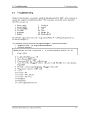
... card slot 12. PC with the ISO/DIS 8764-1:1996. 3. External USB Keyboard 12. Modem 9. Test Program operations are given in Chapter 4. The following tools are : 1. Wraparound connector for implementing the Diagnostics procedures: 1. External USB mouse 13. Display 7. Wireless LAN The Detailed replacement procedures are described in Chapter 3. Headphone 14. Diagnostics Disk (Test program for FDD testing) 5. Work disk (for maintenance) 2. Toshiba MS-DOS system FD 4. Tester 10. 2.1 Troubleshooting 2 Troubleshooting 2 2.1 Troubleshooting...
... card slot 12. PC with the ISO/DIS 8764-1:1996. 3. External USB Keyboard 12. Modem 9. Test Program operations are given in Chapter 4. The following tools are : 1. Wraparound connector for implementing the Diagnostics procedures: 1. External USB mouse 13. Display 7. Wireless LAN The Detailed replacement procedures are described in Chapter 3. Headphone 14. Diagnostics Disk (Test program for FDD testing) 5. Work disk (for maintenance) 2. Toshiba MS-DOS system FD 4. Tester 10. 2.1 Troubleshooting 2 Troubleshooting 2 2.1 Troubleshooting...

Maintenance Manual
Page 97
... Subtest Name ROM checksum Fan ON/OFF Geyserville Quick charge DMI read DMI write CPU Temperature Conventional memory Protected mode Memory module Cache memory L2 Cache memory Stress Pressed key display Pressed key code display Pointing Stick USB test Internet/Mail key VRAM read /write Random address/data Write specified address Read specified address PORTEGE R100 Maintenance Manual (960-440) 3-7 3.3 SubtestSubtest 3 Tests and Diagnostics 3.3 Subtest Table 3-1 lists the subtest names for LCD "H" pattern display LCD Brightness Sequential read...
... Subtest Name ROM checksum Fan ON/OFF Geyserville Quick charge DMI read DMI write CPU Temperature Conventional memory Protected mode Memory module Cache memory L2 Cache memory Stress Pressed key display Pressed key code display Pointing Stick USB test Internet/Mail key VRAM read /write Random address/data Write specified address Read specified address PORTEGE R100 Maintenance Manual (960-440) 3-7 3.3 SubtestSubtest 3 Tests and Diagnostics 3.3 Subtest Table 3-1 lists the subtest names for LCD "H" pattern display LCD Brightness Sequential read...

Maintenance Manual
Page 130
... appears. 3-40 PORTEGE R100 Maintenance Manual (960-440) 3 Tests and Diagnostics 3.16 Sound/LAN/Modem Test Completing SoundMAX/ICH microphone capture test End time XXX XXX XX XX*XX:XX XXXX System Status 0x0 Performing SoundMAX/ICH play buffer to line out Start Time: XXX XXX XX XX:XX:XX XXXX Play to destination is LINEOUT Volume requested is...
... appears. 3-40 PORTEGE R100 Maintenance Manual (960-440) 3 Tests and Diagnostics 3.16 Sound/LAN/Modem Test Completing SoundMAX/ICH microphone capture test End time XXX XXX XX XX*XX:XX XXXX System Status 0x0 Performing SoundMAX/ICH play buffer to line out Start Time: XXX XXX XX XX:XX:XX XXXX Play to destination is LINEOUT Volume requested is...

Maintenance Manual
Page 132
... Error Thermistor Error EC read Error LAN loopback Error 1394 date Error FAN test Error Parity error Protected mode not change Memory write/read error Cache memory error 2nd Cache error TAG-RAM error Mouse interface error IPS interface error Interface error Retransmit error Mouse handler not support PS/2 mouse & IPS not Bad Command Error Address Mark Not Found Write Protected Record Not Found Media Removed DMA Overrun Error DMA Boundary Error CRC Error FDC Error Seek Error Not Drive Error Time Out Error Write Buffer Error 3-42 PORTEGE R100 Maintenance Manual...
... Error Thermistor Error EC read Error LAN loopback Error 1394 date Error FAN test Error Parity error Protected mode not change Memory write/read error Cache memory error 2nd Cache error TAG-RAM error Mouse interface error IPS interface error Interface error Retransmit error Mouse handler not support PS/2 mouse & IPS not Bad Command Error Address Mark Not Found Write Protected Record Not Found Media Removed DMA Overrun Error DMA Boundary Error CRC Error FDC Error Seek Error Not Drive Error Time Out Error Write Buffer Error 3-42 PORTEGE R100 Maintenance Manual...

Maintenance Manual
Page 154
... Power Mode) Low Makes CPU processing speed low. (Default in the condition below . xx Min. Automatically turns off if you make no entry (including no operation of time. The duration xx can be changed in Low Power Mode) (b) CPU Sleep Mode Use this option to 1, 3, 5, 10, 15, 20 or 30 minutes. 3-64 PORTEGE R100 Maintenance Manual (960-440) For details, see Battery Save Options below : (*2) Operating by the battery (*3) Using the AC adapter User Setting Use this option to disable or set...
... Power Mode) Low Makes CPU processing speed low. (Default in the condition below . xx Min. Automatically turns off if you make no entry (including no operation of time. The duration xx can be changed in Low Power Mode) (b) CPU Sleep Mode Use this option to 1, 3, 5, 10, 15, 20 or 30 minutes. 3-64 PORTEGE R100 Maintenance Manual (960-440) For details, see Battery Save Options below : (*2) Operating by the battery (*3) Using the AC adapter User Setting Use this option to disable or set...

Maintenance Manual
Page 221
Caution: Use a Philips screwdriver with type 0 bit to remove the screws. Figure 4-41 Replacing Toshiba fluorescent lamp(2) 4-52 PORTEGE R100 Maintenance Manual (960-440) Removing screws 1) Spread out the insulation sheet without detaching from the bezel side, as shown in the figure below. 2) Remove the left side screws and right side screws in the order c shown in the figure below. 4 Replacement Procedures 4.19 Fluorescent Lamp 2.
Caution: Use a Philips screwdriver with type 0 bit to remove the screws. Figure 4-41 Replacing Toshiba fluorescent lamp(2) 4-52 PORTEGE R100 Maintenance Manual (960-440) Removing screws 1) Spread out the insulation sheet without detaching from the bezel side, as shown in the figure below. 2) Remove the left side screws and right side screws in the order c shown in the figure below. 4 Replacement Procedures 4.19 Fluorescent Lamp 2.

Resource Guide
Page 7
... mode, data will be lost. To confirm compatibility, check its documentation. You may want to the power cable. Installing additional memory (optional) Before you use . If you install or remove a memory module while the computer is available for additional configuration steps, or see "Setting up your computer through one from the outlet with enough memory to a wall outlet and turn off the computer using the Start menu. One memory slot...
... mode, data will be lost. To confirm compatibility, check its documentation. You may want to the power cable. Installing additional memory (optional) Before you use . If you install or remove a memory module while the computer is available for additional configuration steps, or see "Setting up your computer through one from the outlet with enough memory to a wall outlet and turn off the computer using the Start menu. One memory slot...

Resource Guide
Page 22
... brightness controls on the external monitor. If another PCMCIA-equipped computer is available, try the card in the electronic user's guide for the built-in screen. Here are some common problems and their solutions: Resolving PC Card problems The slots appear dead and cards that the cable connecting the external monitor to insert PC Cards. ❖ Make sure all cables are securely connected. ❖ Occasionally a defective PC Card slips through quality control. See "Using...
... brightness controls on the external monitor. If another PCMCIA-equipped computer is available, try the card in the electronic user's guide for the built-in screen. Here are some common problems and their solutions: Resolving PC Card problems The slots appear dead and cards that the cable connecting the external monitor to insert PC Cards. ❖ Make sure all cables are securely connected. ❖ Occasionally a defective PC Card slips through quality control. See "Using...

Resource Guide
Page 43
... 43 memory adding 7 removing expansion slot cover 8 removing module 9 Microsoft Windows XP 3 monitor not working 21 moving the computer 13 O operating system 3 optional devices 29 P PC Card checklist 22 computer stops working 23 inserting 11 problem solving 22 removing 11 replacing 11 port specifications 27 power cable connectors 24 computer will not start 20 monitoring 14 specifications 26 power devices 28, 29 precautions 5 primary control button 13 printer connecting 7 problem solving computer hangs when PC Card inserted 23 computer will not power...
... 43 memory adding 7 removing expansion slot cover 8 removing module 9 Microsoft Windows XP 3 monitor not working 21 moving the computer 13 O operating system 3 optional devices 29 P PC Card checklist 22 computer stops working 23 inserting 11 problem solving 22 removing 11 replacing 11 port specifications 27 power cable connectors 24 computer will not start 20 monitoring 14 specifications 26 power devices 28, 29 precautions 5 primary control button 13 printer connecting 7 problem solving computer hangs when PC Card inserted 23 computer will not power...


