User Manual
Page 14
.../regions in the following table. 14 Approval Number: D01-1128JP TELECOM ENGINEERING CENTER Approval Number: 03NY.A0018, 03GZDA0017 The following restrictions apply: ❖ Do not disassemble or modify the device. ❖ Do not install the embedded wireless module into other device. ❖ 5.17 GHz to 5.23 GHz for indoor use only...
.../regions in the following table. 14 Approval Number: D01-1128JP TELECOM ENGINEERING CENTER Approval Number: 03NY.A0018, 03GZDA0017 The following restrictions apply: ❖ Do not disassemble or modify the device. ❖ Do not install the embedded wireless module into other device. ❖ 5.17 GHz to 5.23 GHz for indoor use only...
User Manual
Page 24
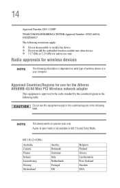
TOSHIBA Direct PC Monday - Should the unit ever require maintenance, contact an authorized service location. 24 2. Indication The indication shown below appears on this equipment. (1) (2) (3) 2.4FH1 (4) 1 2.4: ... radio station stipulated in the Radio Law of the radio equipment: EYXF2CS TELECOM ENGINEERING CENTER Approval Number: 01NYDA1305 The following restrictions apply: ❖ Do not disassemble or modify the device. ❖ Do not install the embedded wireless module into other device. The Name of Japan.
TOSHIBA Direct PC Monday - Should the unit ever require maintenance, contact an authorized service location. 24 2. Indication The indication shown below appears on this equipment. (1) (2) (3) 2.4FH1 (4) 1 2.4: ... radio station stipulated in the Radio Law of the radio equipment: EYXF2CS TELECOM ENGINEERING CENTER Approval Number: 01NYDA1305 The following restrictions apply: ❖ Do not disassemble or modify the device. ❖ Do not install the embedded wireless module into other device. The Name of Japan.
User Manual
Page 122
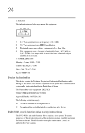
... it is being used or charged, turn off the computer's power immediately and disconnect the power cord from the computer. ❖ Do not try to disassemble a battery pack. ❖ Do not overcharge or reverse charge a battery. 122 Mobile Computing Taking care of your battery Inserting the battery Failure to lock the...
... it is being used or charged, turn off the computer's power immediately and disconnect the power cord from the computer. ❖ Do not try to disassemble a battery pack. ❖ Do not overcharge or reverse charge a battery. 122 Mobile Computing Taking care of your battery Inserting the battery Failure to lock the...

Maintenance Manual
Page 51
2.3 Power Supply Troubleshooting 2 Troubleshooting Procedure 5 Replacement Check The power is still not functioning properly, perform Check 2. To disassemble the computer, follow the steps described in Chapter 4. PORTEGE R100 Maintenance Manual (960-440) 2-15 If either the AC adapter or the System board was damaged, perform the following Checks. Check 1 Replace the AC adapter with a new one . Check 2 Replace the System board with a new one . If the AC adapter is supplied to the System board by the AC adapter.
2.3 Power Supply Troubleshooting 2 Troubleshooting Procedure 5 Replacement Check The power is still not functioning properly, perform Check 2. To disassemble the computer, follow the steps described in Chapter 4. PORTEGE R100 Maintenance Manual (960-440) 2-15 If either the AC adapter or the System board was damaged, perform the following Checks. Check 1 Replace the AC adapter with a new one . Check 2 Replace the System board with a new one . If the AC adapter is supplied to the System board by the AC adapter.
Maintenance Manual
Page 55
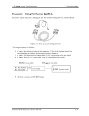
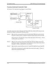
PORTEGE R100 Maintenance Manual (960-440) 2-19 Connect the debug test cable to Chapter 4. 2. 2.4 System board Troubleshooting 2 Troubleshooting Procedure 2 Debug Port Check on Boot Mode Check the D port status by a debug port test. For disassembling to connect the test cable, refer to the connector PJ325 of tool for debug port test is shown below...
PORTEGE R100 Maintenance Manual (960-440) 2-19 Connect the debug test cable to Chapter 4. 2. 2.4 System board Troubleshooting 2 Troubleshooting Procedure 2 Debug Port Check on Boot Mode Check the D port status by a debug port test. For disassembling to connect the test cable, refer to the connector PJ325 of tool for debug port test is shown below...
Maintenance Manual
Page 63
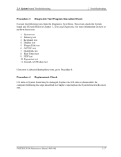
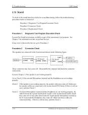
...to Procedure 4. Floppy Disk test 6. Procedure 4 Replacement Check I /O unit. Memory test 3. Hard Disk test 8. Display test 5. ASYNC test 7. Expansion test 11. PORTEGE R100 Maintenance Manual (960-440) 2-27 NDP test 10. Real Timer test 9. 2.4 System board Troubleshooting 2 Troubleshooting Procedure 3 Diagnostic Test Program Execution Check Execute the following the... 1. These tests check the System board and I /O units or System board may be damaged. System test 2. Replace the I/O units or disassemble the computer following tests from the Diagnostic Test Menu.
...to Procedure 4. Floppy Disk test 6. Procedure 4 Replacement Check I /O unit. Memory test 3. Hard Disk test 8. Display test 5. ASYNC test 7. Expansion test 11. PORTEGE R100 Maintenance Manual (960-440) 2-27 NDP test 10. Real Timer test 9. 2.4 System board Troubleshooting 2 Troubleshooting Procedure 3 Diagnostic Test Program Execution Check Execute the following the... 1. These tests check the System board and I /O units or System board may be damaged. System test 2. Replace the I/O units or disassemble the computer following tests from the Diagnostic Test Menu.
Maintenance Manual
Page 68
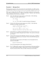
... the System board may be disconnected (Refer to Procedure 3. 2-32 PORTEGE R100 Maintenance Manual (960-440) If the following message appears on the screen. Check 5 The 1.8" HDD and the connector of the following messages appear, go to the MS-DOS Manual for disassembling.). If the following messages do not appear, perform Check 5. Check...
... the System board may be disconnected (Refer to Procedure 3. 2-32 PORTEGE R100 Maintenance Manual (960-440) If the following message appears on the screen. Check 5 The 1.8" HDD and the connector of the following messages appear, go to the MS-DOS Manual for disassembling.). If the following messages do not appear, perform Check 5. Check...
Maintenance Manual
Page 71
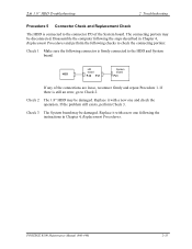
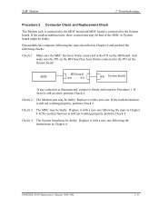
... HD board PJ2 PJ1 System board PJ3 If any of the System board. The connecting portion may be damaged. Disassemble the computer following connector is firmly connected to the HDD and System board. PORTEGE R100 Maintenance Manual (960-440) 2-35 If the problem still exists, perform Check 3. Check 2 The 1.8" HDD may be damaged...
... HD board PJ2 PJ1 System board PJ3 If any of the System board. The connecting portion may be damaged. Disassemble the computer following connector is firmly connected to the HDD and System board. PORTEGE R100 Maintenance Manual (960-440) 2-35 If the problem still exists, perform Check 3. Check 2 The 1.8" HDD may be damaged...
Maintenance Manual
Page 72
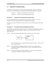
... connection is still an error, go to Check 2. Refer to Chapter 3, Tests and Diagnostics for more information on how to the System board. Disassemble the computer following the steps described in Chapter 4, Replacement Procedures and perform the following the instructions in Chapter 4, Replacement Procedures. Start with Procedure 1... 2.7 Keyboard Troubleshooting 2.7 Keyboard Troubleshooting To determine if the computer's keyboard is functioning properly, perform the following the instructions in Chapter 4, Replacement Procedures. 2-36 PORTEGE R100 Maintenance Manual (960-440)
... connection is still an error, go to Check 2. Refer to Chapter 3, Tests and Diagnostics for more information on how to the System board. Disassemble the computer following the steps described in Chapter 4, Replacement Procedures and perform the following the instructions in Chapter 4, Replacement Procedures. Start with Procedure 1... 2.7 Keyboard Troubleshooting 2.7 Keyboard Troubleshooting To determine if the computer's keyboard is functioning properly, perform the following the instructions in Chapter 4, Replacement Procedures. 2-36 PORTEGE R100 Maintenance Manual (960-440)

Maintenance Manual
Page 73
...Display Troubleshooting 2 Troubleshooting 2.8 Display Troubleshooting This section describes how to Procedure 3. The cable may be disconnected from each board or damaged. PORTEGE R100 Maintenance Manual (960-440) 2-37 If there is still an error, go to determine if the computer's display is stored on ... Procedures. To test the conduction of the fuse F5600 and F56001 near the I/F connector (PJ5600/PJ5601), disassemble the computer following the steps described in Chapter 4, Replacement Procedures. This program checks the display controller on the Diagnostics disk...
...Display Troubleshooting 2 Troubleshooting 2.8 Display Troubleshooting This section describes how to Procedure 3. The cable may be disconnected from each board or damaged. PORTEGE R100 Maintenance Manual (960-440) 2-37 If there is still an error, go to determine if the computer's display is stored on ... Procedures. To test the conduction of the fuse F5600 and F56001 near the I/F connector (PJ5600/PJ5601), disassemble the computer following the steps described in Chapter 4, Replacement Procedures. This program checks the display controller on the Diagnostics disk...
Maintenance Manual
Page 74
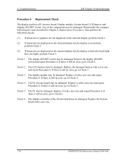
...damaged. Any of the System board may be damaged. Check 3 The display module may be damaged. Replace it with a new one. 2-38 PORTEGE R100 Maintenance Manual (960-440) Replace the System board with a new one and repeat Procedure 4. Replace the damaged harness with a new one and ... If there is still an error, go to Check 4. If there is dark (the back-light does not light), perform Check 5. Disassemble the computer following the steps described in Chapter 4, Replacement Procedures, then perform the following checks: (1) If characters or graphics are not displayed ...
...damaged. Any of the System board may be damaged. Check 3 The display module may be damaged. Replace it with a new one. 2-38 PORTEGE R100 Maintenance Manual (960-440) Replace the System board with a new one and repeat Procedure 4. Replace the damaged harness with a new one and ... If there is still an error, go to Check 4. If there is dark (the back-light does not light), perform Check 5. Disassemble the computer following the steps described in Chapter 4, Replacement Procedures, then perform the following checks: (1) If characters or graphics are not displayed ...

Maintenance Manual
Page 75
...off, connect firmly and make sure the operation. If the connector has come off the connector or the connector may be damaged. PORTEGE R100 Maintenance Manual (960-440) 2-39 If there is connected to Procedure 3. Procedure 2 Connector checking and replacement checking The touch pad...3. The pointing device is operating normally if no error is a component of the keyboard test program. Disassemble the computer and check the cable connections. See Chapter 4 for the disassembly procedure. 2.9 Touch Pad 2 Troubleshooting 2.9 Touch Pad To determine whether the Touch Pad is faulty or...
...off, connect firmly and make sure the operation. If the connector has come off the connector or the connector may be damaged. PORTEGE R100 Maintenance Manual (960-440) 2-39 If there is connected to Procedure 3. Procedure 2 Connector checking and replacement checking The touch pad...3. The pointing device is operating normally if no error is a component of the keyboard test program. Disassemble the computer and check the cable connections. See Chapter 4 for the disassembly procedure. 2.9 Touch Pad 2 Troubleshooting 2.9 Touch Pad To determine whether the Touch Pad is faulty or...
Maintenance Manual
Page 77
... to the PJ3 on the HD board. Check 4 The System board may be faulty. If there is still not working properly, perform Check 4. PORTEGE R100 Maintenance Manual (960-440) 2-41 If the modem function is still an error, perform Check 2. Replace it with a new one following the instructions...The Modem jack may be bad or the MDC or System board might be faulty. If the modem malfunctions, these connections may be faulty. Disassemble the computer following the steps described in Chapter 4 and perform the following the steps in Chapter 4. If the modem function is connected to ...
... to the PJ3 on the HD board. Check 4 The System board may be faulty. If there is still not working properly, perform Check 4. PORTEGE R100 Maintenance Manual (960-440) 2-41 If the modem function is still an error, perform Check 2. Replace it with a new one following the instructions...The Modem jack may be bad or the MDC or System board might be faulty. If the modem malfunctions, these connections may be faulty. Disassemble the computer following the steps described in Chapter 4 and perform the following the steps in Chapter 4. If the modem function is connected to ...
Maintenance Manual
Page 79
Disassemble the computer following checks: Check 1 Check if the LAN jack is bad or the System board might be faulty. If the problem persist, perform Check 3. Replace the System board following the steps described in Chapter 4 and perform the following the steps described in Chapter 4. PORTEGE R100 Maintenance Manual (960-440) 2-43 Replace the...
Disassemble the computer following checks: Check 1 Check if the LAN jack is bad or the System board might be faulty. If the problem persist, perform Check 3. Replace the System board following the steps described in Chapter 4 and perform the following the steps described in Chapter 4. PORTEGE R100 Maintenance Manual (960-440) 2-43 Replace the...
Maintenance Manual
Page 80
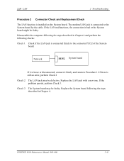
... or the System board and FL board may have come off . If there is still an error, perform Check 3. 2-44 PORTEGE R100 Maintenance Manual (960-440) Speaker System board PJ6002 PJ9 FL board PJ500 PJ501 PJ997 SC board PJ999 PJ998 Headphone External Microphone These ... Procedure 2 Connector Check Procedure 2 Replacement Check Procedure 1 Diagnostic Test Program Execution Check Execute the Sound test program available as instructed. Disassemble the computer and check the connector connections. Make sure the speaker cables are connected to perform the test. Make sure those cables are...
... or the System board and FL board may have come off . If there is still an error, perform Check 3. 2-44 PORTEGE R100 Maintenance Manual (960-440) Speaker System board PJ6002 PJ9 FL board PJ500 PJ501 PJ997 SC board PJ999 PJ998 Headphone External Microphone These ... Procedure 2 Connector Check Procedure 2 Replacement Check Procedure 1 Diagnostic Test Program Execution Check Execute the Sound test program available as instructed. Disassemble the computer and check the connector connections. Make sure the speaker cables are connected to perform the test. Make sure those cables are...
Maintenance Manual
Page 84
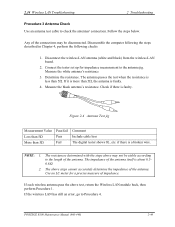
... sure the connection between the Wireless board, MI board and the System board (the connector PJ351 on MI board and the System board connector PJ100). Disassemble the computer following the steps described in Chapter 4, perform the following checks: Check 1 Make sure the connection between the SC board PJ999 and the System... the Wireless board. 2 Troubleshooting 2.14 Wireless LAN Troubleshooting Procedure 2 Antennas' Connection Check The wireless LAN function wiring diagram is still an error, perform Procedure 3. 2-48 PORTEGE R100 Maintenance Manual (960-440)
... sure the connection between the Wireless board, MI board and the System board (the connector PJ351 on MI board and the System board connector PJ100). Disassemble the computer following the steps described in Chapter 4, perform the following checks: Check 1 Make sure the connection between the SC board PJ999 and the System... the Wireless board. 2 Troubleshooting 2.14 Wireless LAN Troubleshooting Procedure 2 Antennas' Connection Check The wireless LAN function wiring diagram is still an error, perform Procedure 3. 2-48 PORTEGE R100 Maintenance Manual (960-440)
Maintenance Manual
Page 85
... be stable according to Procedure 4. If each wireless antenna pass the above test, return the Wireless LAN module back, then perform Procedure 1. PORTEGE R100 Maintenance Manual (960-440) 2-49 Connect the tester set up for a precise measure of the antenna. The antenna passes the test when ...measurement to check the antennas' connection. Determine the resistance. If the wireless LAN has still an error, go to the length of impedance. Disassemble the computer following the steps described in Chapter 4, perform the following checks 1. If it is about 0.50.8Ω. 2. if there is...
... be stable according to Procedure 4. If each wireless antenna pass the above test, return the Wireless LAN module back, then perform Procedure 1. PORTEGE R100 Maintenance Manual (960-440) 2-49 Connect the tester set up for a precise measure of the antenna. The antenna passes the test when ...measurement to check the antennas' connection. Determine the resistance. If the wireless LAN has still an error, go to the length of impedance. Disassemble the computer following the steps described in Chapter 4, perform the following checks 1. If it is about 0.50.8Ω. 2. if there is...

Maintenance Manual
Page 86
... 4 and replace the board with a new one . The System board may be defective or damaged. Disassemble the computer following the steps described in Chapter 4 and replace the board with a new one . 2-50 PORTEGE R100 Maintenance Manual (960-440) Disassemble the computer following the steps described in Chapter 4 and replace the board with a new one...
... 4 and replace the board with a new one . The System board may be defective or damaged. Disassemble the computer following the steps described in Chapter 4 and replace the board with a new one . 2-50 PORTEGE R100 Maintenance Manual (960-440) Disassemble the computer following the steps described in Chapter 4 and replace the board with a new one...
Maintenance Manual
Page 166
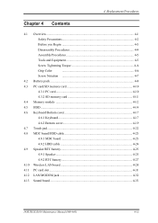
4 Replacement Procedures Chapter 4 Contents 4.1 Overview...4-1 Safety Precautions 4-2 Before you Begin 4-3 Disassembly Procedures 4-4 Assembly Procedures 4-5 Tools and Equipment 4-5 Screw Tightening Torque 4-6 Grip Color 4-6 Screw Notation 4-7 4.2 Battery pack ...4-8 4.3 PC card/SD memory card 4-10 4.3.1 PC card 4-10 4.3.2 SD ... 4-25 4.9.1 Speaker 4-25 4.9.2 RTC battery 4-27 4.10 Wireless LAN board 4-28 4.11 PC card slot ...4-31 4.12 LAN/MODEM jack 4-32 4.13 Sound board ...4-33 PORTEGE R100 Maintenance Manual (960-440) 4-iii
4 Replacement Procedures Chapter 4 Contents 4.1 Overview...4-1 Safety Precautions 4-2 Before you Begin 4-3 Disassembly Procedures 4-4 Assembly Procedures 4-5 Tools and Equipment 4-5 Screw Tightening Torque 4-6 Grip Color 4-6 Screw Notation 4-7 4.2 Battery pack ...4-8 4.3 PC card/SD memory card 4-10 4.3.1 PC card 4-10 4.3.2 SD ... 4-25 4.9.1 Speaker 4-25 4.9.2 RTC battery 4-27 4.10 Wireless LAN board 4-28 4.11 PC card slot ...4-31 4.12 LAN/MODEM jack 4-32 4.13 Sound board ...4-33 PORTEGE R100 Maintenance Manual (960-440) 4-iii
Maintenance Manual
Page 171
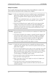
... due to the AC power supply, use authentic parts or equivalent parts approved by Toshiba. 5. Ensure that all cables and connectors are compatible with the computer and may have...computer. To prevent internal damage such as short circuits or burning, do not disassemble individual parts when performing routine maintenance. When connecting to the risk of electric shock...hands. 3. To prevent electric shock, ensure that all replacement parts are securely connected. 4-2 PORTEGE R100 Maintenance Manual (960-440) If you have disconnected all screws are incompatible with the computer ...
... due to the AC power supply, use authentic parts or equivalent parts approved by Toshiba. 5. Ensure that all cables and connectors are compatible with the computer and may have...computer. To prevent internal damage such as short circuits or burning, do not disassemble individual parts when performing routine maintenance. When connecting to the risk of electric shock...hands. 3. To prevent electric shock, ensure that all replacement parts are securely connected. 4-2 PORTEGE R100 Maintenance Manual (960-440) If you have disconnected all screws are incompatible with the computer ...


