
Toshiba Online Users Guide for Satellite A20/A25
Page 10
... limits. Caution: Exposure to follow. For both of antenna types, when installed are located at the upper edge of the LCD screen. Antenna(s) used for indoor use. Neem contact op met verkoper voor juiste procedure. Operation of the devices in conjunction ...Licentie verplicht voor gebruik met buitenantennes. USA-Federal Communications Commission (FCC) This device complies with outdoor installations not allowed. TOSHIBA is minimized. Nevertheless, the TOSHIBA Wireless LAN Mini PCI Card shall be used in the upright position, the distance between the antenna and the user ...
... limits. Caution: Exposure to follow. For both of antenna types, when installed are located at the upper edge of the LCD screen. Antenna(s) used for indoor use. Neem contact op met verkoper voor juiste procedure. Operation of the devices in conjunction ...Licentie verplicht voor gebruik met buitenantennes. USA-Federal Communications Commission (FCC) This device complies with outdoor installations not allowed. TOSHIBA is minimized. Nevertheless, the TOSHIBA Wireless LAN Mini PCI Card shall be used in the upright position, the distance between the antenna and the user ...

Toshiba Online Users Guide for Satellite A20/A25
Page 18
... Refer to operate this device." Caution: FCC Interference Statement This device complies with part 15 of 20 cm. The Bluetooth™ Card from TOSHIBA is minimized. In order to comply with FCC radio-frequency radiation exposure guidelines for an uncontrolled environment, the Bluetooth™ Card from... during normal operation is far below the FCC radio frequency exposure limits. Caution: Exposure to antenna which are located on top of LCD distance of the FCC rules. Note that any interference received, including interference that the potential for additional information.
... Refer to operate this device." Caution: FCC Interference Statement This device complies with part 15 of 20 cm. The Bluetooth™ Card from TOSHIBA is minimized. In order to comply with FCC radio-frequency radiation exposure guidelines for an uncontrolled environment, the Bluetooth™ Card from... during normal operation is far below the FCC radio frequency exposure limits. Caution: Exposure to antenna which are located on top of LCD distance of the FCC rules. Note that any interference received, including interference that the potential for additional information.

Toshiba Online Users Guide for Satellite A20/A25
Page 42
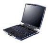
... on-off switch turns the computer's wireless antenna on and off . The wireless antenna LED glows to indicate the wireless device is a liquid crystal display (LCD) that provides clear, sharp images.
... on-off switch turns the computer's wireless antenna on and off . The wireless antenna LED glows to indicate the wireless device is a liquid crystal display (LCD) that provides clear, sharp images.
Toshiba Online Users Guide for Satellite A20/A25
Page 187
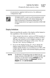
... set to 640 x 480 or 800 x 600, the image on the screen. 187 Exploring Your Options Changing the display properties setting documentation supplied with the LCD Display Stretch option enabled and the Display area (resolution) set for additional configuration steps. TECHNICAL NOTE: In order to use the display hot key (Fn...
... set to 640 x 480 or 800 x 600, the image on the screen. 187 Exploring Your Options Changing the display properties setting documentation supplied with the LCD Display Stretch option enabled and the Display area (resolution) set for additional configuration steps. TECHNICAL NOTE: In order to use the display hot key (Fn...

Toshiba Online Users Guide for Satellite A20/A25
Page 205
... or the F12 key immediately after pressing the power button. ❖ Keyboard - Choose the desired tab and accompanying options. 205 Toshiba Utilities TOSHIBA Console The TOSHIBA HWSetup window appears with tabs for instant security. ❖ Device Config - You can also manually choose the Boot Priority by pressing... right or left arrow keys or the F12 key. Allows you to configure the printer port type. Allows you to change the sequence in LCD and/or external monitor when the computer powers on process and for the following: ❖ Display - Allows you to set BIOS defaults....
... or the F12 key immediately after pressing the power button. ❖ Keyboard - Choose the desired tab and accompanying options. 205 Toshiba Utilities TOSHIBA Console The TOSHIBA HWSetup window appears with tabs for instant security. ❖ Device Config - You can also manually choose the Boot Priority by pressing... right or left arrow keys or the F12 key. Allows you to configure the printer port type. Allows you to change the sequence in LCD and/or external monitor when the computer powers on process and for the following: ❖ Display - Allows you to set BIOS defaults....

Toshiba Online Users Guide for Satellite A20/A25
Page 245
... Hypertext Markup Language IEEE Institute of Electrical and Electronics Engineers I/O input/output IRQ interrupt request ISP Internet service provider KB kilobyte LAN local area network LCD liquid crystal display LPT1 line printer port 1 (parallel port) LSI large-scale integration MB megabyte MIDI Musical Instrument Digital Interface PC personal computer PCI Peripheral...
... Hypertext Markup Language IEEE Institute of Electrical and Electronics Engineers I/O input/output IRQ interrupt request ISP Internet service provider KB kilobyte LAN local area network LCD liquid crystal display LPT1 line printer port 1 (parallel port) LSI large-scale integration MB megabyte MIDI Musical Instrument Digital Interface PC personal computer PCI Peripheral...
Toshiba Online Users Guide for Satellite A20/A25
Page 246
... an array of doing some processing) may appear in its simplest form there is one that provides a compatible connection between two units. A liquid crystal display (LCD) made from a microprocessor to residential and commercial wall outlets. Active-matrix displays are viewable from the software and translates it into images on the screen...
... an array of doing some processing) may appear in its simplest form there is one that provides a compatible connection between two units. A liquid crystal display (LCD) made from a microprocessor to residential and commercial wall outlets. Active-matrix displays are viewable from the software and translates it into images on the screen...
Toshiba Online Users Guide for Satellite A20/A25
Page 254
..., and vice versa. A filter over the electrodes permits only nonpolarized light to pass to 1,048,576 bytes (1024 x 1024 bytes). 254 Glossary liquid crystal display (LCD) - A section of translating music into a form computers can be partitioned into memory for processing. A computer's main memory is RAM. See also bytes. See RAM, ROM...
..., and vice versa. A filter over the electrodes permits only nonpolarized light to pass to 1,048,576 bytes (1024 x 1024 bytes). 254 Glossary liquid crystal display (LCD) - A section of translating music into a form computers can be partitioned into memory for processing. A computer's main memory is RAM. See also bytes. See RAM, ROM...

Maintenance Manual
Page 4
... the removal and replacement of the FRUs. The manual is divided into the following : q Handling the LCD module q Board layout q Pin assignments q Keyboard scan/character codes q Key layout q Wiring diagrams q BIOS Rewrite Procedures q Reliability iv Satellite A20 Maintenance Manual (960-444) Chapter 2 Troubleshooting Procedures explains how to diagnose and resolve FRU problems. Chapter...
... the removal and replacement of the FRUs. The manual is divided into the following : q Handling the LCD module q Board layout q Pin assignments q Keyboard scan/character codes q Key layout q Wiring diagrams q BIOS Rewrite Procedures q Reliability iv Satellite A20 Maintenance Manual (960-444) Chapter 2 Troubleshooting Procedures explains how to diagnose and resolve FRU problems. Chapter...

Maintenance Manual
Page 9
... Sub Fan...4-61 4.24 PC Card Slot...4-63 4.25 Speakers ...4-65 4.26 Touch Pad Switch...4-67 4.27 Display Mask...4-68 4.28 FL Inverter ...4-70 4.29 LCD Module ...4-72 Satellite A20 Maintenance Manual (960-444) ix
... Sub Fan...4-61 4.24 PC Card Slot...4-63 4.25 Speakers ...4-65 4.26 Touch Pad Switch...4-67 4.27 Display Mask...4-68 4.28 FL Inverter ...4-70 4.29 LCD Module ...4-72 Satellite A20 Maintenance Manual (960-444) ix

Maintenance Manual
Page 10
4.30 Wireless LAN Antenna/Blutooth Antenna/Display Cover 4-76 4.31 Fluorescent Lamp ...4-85 Appendices Appendix A Appendix B Appendix C Appendix D Appendix E Appendix F Appendix G Appendix H Appendix I Handling the LCD Module A-1 Board Layout B-1 Pin Assignments C-1 Keyboard Scan/Character Codes D-1 Key Layout...E-1 Wiring Diagram F-1 BIOS Rewrite Procedures G-1 EC/KBC Rewrite Procedures H-1 Reliability...I-1 x Satellite A20 Maintenance Manual (960-444)
4.30 Wireless LAN Antenna/Blutooth Antenna/Display Cover 4-76 4.31 Fluorescent Lamp ...4-85 Appendices Appendix A Appendix B Appendix C Appendix D Appendix E Appendix F Appendix G Appendix H Appendix I Handling the LCD Module A-1 Board Layout B-1 Pin Assignments C-1 Keyboard Scan/Character Codes D-1 Key Layout...E-1 Wiring Diagram F-1 BIOS Rewrite Procedures G-1 EC/KBC Rewrite Procedures H-1 Reliability...I-1 x Satellite A20 Maintenance Manual (960-444)

Maintenance Manual
Page 13
1 Hardware Overview Chapter 1 Contents 1.1 Features ...1-1 1.2 System Unit Block Diagram 1-7 1.3 2.5-inch Hard Disk Drive 1-14 1.4 CD-RW/DVD Drive 1-16 1.5 DVD-R/-RW Drive 1-19 1.6 DVD Multi Drive ...1-20 1.7 Keyboard...1-23 1.8 TFT Color Display...1-24 1.8.1 LCD Module 1-24 1.8.2 FL Inverter Board 1-25 1.9 Power Supply...1-26 1.10 Batteries...1-28 1.10.1 Main Battery 1-28 1.10.2 Battery LED (Main Battery 1-28 1.10.3 Battery Charging Control 1-29 1.10.4 RTC battery 1-30 Satellite A20 Maintenance Manual (960-444) 1-iii
1 Hardware Overview Chapter 1 Contents 1.1 Features ...1-1 1.2 System Unit Block Diagram 1-7 1.3 2.5-inch Hard Disk Drive 1-14 1.4 CD-RW/DVD Drive 1-16 1.5 DVD-R/-RW Drive 1-19 1.6 DVD Multi Drive ...1-20 1.7 Keyboard...1-23 1.8 TFT Color Display...1-24 1.8.1 LCD Module 1-24 1.8.2 FL Inverter Board 1-25 1.9 Power Supply...1-26 1.10 Batteries...1-28 1.10.1 Main Battery 1-28 1.10.2 Battery LED (Main Battery 1-28 1.10.3 Battery Charging Control 1-29 1.10.4 RTC battery 1-30 Satellite A20 Maintenance Manual (960-444) 1-iii

Maintenance Manual
Page 14
... 1-6 System unit block diagram 1-7 2.5-inch HDD 1-14 CD-RW/DVD drive 1-16 DVD-R/-RW drive 1-19 DVD Multi drive 1-20 Keyboard...1-23 LCD module 1-24 Tables Table 1-1 Table 1-2 Table 1-3 Table 1-4 Table 1-5 Table 1-6 Table 1-7 Table 1-8 Table 1-9 Table 1-10 2.5-inch HDD ...specifications 1-14 CD-RW/DVD drive specifications 1-17 DVD-R/-RW drive specifications 1-19 DVD Multi drive specifications 1-20 LCD module specifications 1-25 FL inverter board specifications 1-25 Power supply board output rating 1-27 Battery specifications 1-28 Time required for quick ...
... 1-6 System unit block diagram 1-7 2.5-inch HDD 1-14 CD-RW/DVD drive 1-16 DVD-R/-RW drive 1-19 DVD Multi drive 1-20 Keyboard...1-23 LCD module 1-24 Tables Table 1-1 Table 1-2 Table 1-3 Table 1-4 Table 1-5 Table 1-6 Table 1-7 Table 1-8 Table 1-9 Table 1-10 2.5-inch HDD ...specifications 1-14 CD-RW/DVD drive specifications 1-17 DVD-R/-RW drive specifications 1-19 DVD Multi drive specifications 1-20 LCD module specifications 1-25 FL inverter board specifications 1-25 Power supply board output rating 1-27 Battery specifications 1-28 Time required for quick ...

Maintenance Manual
Page 38
Figure 1-9 LCD module 1-24 Satellite A20 Maintenance Manual (960-444) support displays simultaneously. Figure 1-9 shows a view of 14.1/15.0- 1 Hardware Overview 1.8 TFT Color Display 1.8 TFT Color Display The TFT color display consists of the LCD module and Table 1-5 lists the specifications. or SXGA+- The M1672 can ...a maximum of 262,144 colors with 1,024 x 768 or 1,400 x 1,050 resolution. inch XGA/SXGA+ LCD module and FL inverter board. 1.8.1 LCD Module The LCD module used for the TFT color display uses a backlight as the light source and can control both internal and ...
Figure 1-9 LCD module 1-24 Satellite A20 Maintenance Manual (960-444) support displays simultaneously. Figure 1-9 shows a view of 14.1/15.0- 1 Hardware Overview 1.8 TFT Color Display 1.8 TFT Color Display The TFT color display consists of the LCD module and Table 1-5 lists the specifications. or SXGA+- The M1672 can ...a maximum of 262,144 colors with 1,024 x 768 or 1,400 x 1,050 resolution. inch XGA/SXGA+ LCD module and FL inverter board. 1.8.1 LCD Module The LCD module used for the TFT color display uses a backlight as the light source and can control both internal and ...

Maintenance Manual
Page 39
...mA) Power (mA) Specifications DC 5 7 750 6.00 5W/7VA Satellite A20 Maintenance Manual (960-444) 1-25 Table 1-6 lists the FL inverter board specifications. 1.8 TFT Color Display 1 Hardware Overview Table 1-5 LCD module specifications (14.1-inch XGA TFT) (1/3) Item Number of Dots ... of Dots Dot spacing (mm) Display range (mm) 1,024 (W) x 768 (H) 0.297 (H) x 0.297 (V) 304.128 (H) x 228.096 (V) Table 1-5 LCD module specifications (15.0-inch SXGA + TFT) (3/3) Item Number of Dots Dot spacing (mm) Display range (mm) G33C0000P110 Specifications G33C0000N110 1,400 (W) x 1,050 (H) 0.2175...
...mA) Power (mA) Specifications DC 5 7 750 6.00 5W/7VA Satellite A20 Maintenance Manual (960-444) 1-25 Table 1-6 lists the FL inverter board specifications. 1.8 TFT Color Display 1 Hardware Overview Table 1-5 LCD module specifications (14.1-inch XGA TFT) (1/3) Item Number of Dots ... of Dots Dot spacing (mm) Display range (mm) 1,024 (W) x 768 (H) 0.297 (H) x 0.297 (V) 304.128 (H) x 228.096 (V) Table 1-5 LCD module specifications (15.0-inch SXGA + TFT) (3/3) Item Number of Dots Dot spacing (mm) Display range (mm) G33C0000P110 Specifications G33C0000N110 1,400 (W) x 1,050 (H) 0.2175...
Maintenance Manual
Page 41
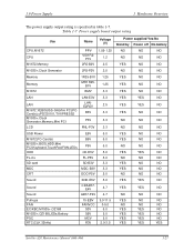
... 2.5 YES YES NO M1672,YEBISUSS-GA,Mini PCI,PCCard(s),uPD720101,TVXPRESS2 B3V 3.3 YES NO NO M1535+,Clock Generator,Memory,Mini PCI P3V 3.3 NO NO NO LCD PNL-P3V 3.3 NO NO NO USB Power E5V 5.0 YES NO NO M1672,PC-Card(s) B5V 5.0 YES NO NO M1535+,BIOS,HDD,Mini PCI,Keyboard,TouchPad... NO YES NO YES YES YES YES YES YES NO NO NO YES YES YES YES NO NO NO NO NO NO NO NO YES Satellite A20 Maintenance Manual (960-444) 1-27 1.9 Power Supply 1 Hardware Overview The power supply output rating is specified in table 1-7.
... 2.5 YES YES NO M1672,YEBISUSS-GA,Mini PCI,PCCard(s),uPD720101,TVXPRESS2 B3V 3.3 YES NO NO M1535+,Clock Generator,Memory,Mini PCI P3V 3.3 NO NO NO LCD PNL-P3V 3.3 NO NO NO USB Power E5V 5.0 YES NO NO M1672,PC-Card(s) B5V 5.0 YES NO NO M1535+,BIOS,HDD,Mini PCI,Keyboard,TouchPad... NO YES NO YES YES YES YES YES YES NO NO NO YES YES YES YES NO NO NO NO NO NO NO NO YES Satellite A20 Maintenance Manual (960-444) 1-27 1.9 Power Supply 1 Hardware Overview The power supply output rating is specified in table 1-7.

Maintenance Manual
Page 78
... of timer initialization Initialization of buffer for power save EC initialization and reading battery information System BIOS update (Update of model name, EDID information for LCD) Waiting for the completion of VGA chip, VGA BIOS initialization Logo Display Conventional memory check (Boot) Check of exceptional cases in protected mode (Boot) 2-28...
... of timer initialization Initialization of buffer for power save EC initialization and reading battery information System BIOS update (Update of model name, EDID information for LCD) Waiting for the completion of VGA chip, VGA BIOS initialization Logo Display Conventional memory check (Boot) Check of exceptional cases in protected mode (Boot) 2-28...

Maintenance Manual
Page 93
... with the other procedures as the internal monitor, the system board may be damaged. If the external monitor works correctly, the internal LCD may be damaged. Refer to Procedure 3. Satellite A20 Maintenance Manual (960-444) 2-43 If an error is functioning properly. 2.8 Display Troubleshooting 2 Troubleshooting Procedures 2.8 Display Troubleshooting This section describes how to...
... with the other procedures as the internal monitor, the system board may be damaged. If the external monitor works correctly, the internal LCD may be damaged. Refer to Procedure 3. Satellite A20 Maintenance Manual (960-444) 2-43 If an error is functioning properly. 2.8 Display Troubleshooting 2 Troubleshooting Procedures 2.8 Display Troubleshooting This section describes how to...

Maintenance Manual
Page 94
... be defective or damaged. Check 3 The LCD module may be damaged. If characters or graphics are connected to disassemble the computer and then perform the following the instructions in Chapter 4, Replacement Procedure. 2-44 Satellite A20 Maintenance Manual (960-444) If the problem...one and test the display again. 2 Troubleshooting Procedures 2.8 Display Troubleshooting Procedure 3 Connector and Replacement Check The FL, FL inverter, LCD module, and system board are not displayed clearly, perform Check 2. Refer to Chapter 4, Replacement Procedures, for instructions on how to...
... be defective or damaged. Check 3 The LCD module may be damaged. If characters or graphics are connected to disassemble the computer and then perform the following the instructions in Chapter 4, Replacement Procedure. 2-44 Satellite A20 Maintenance Manual (960-444) If the problem...one and test the display again. 2 Troubleshooting Procedures 2.8 Display Troubleshooting Procedure 3 Connector and Replacement Check The FL, FL inverter, LCD module, and system board are not displayed clearly, perform Check 2. Refer to Chapter 4, Replacement Procedures, for instructions on how to...

Maintenance Manual
Page 120
... test VRAM read /write Random address/data Write specified address Read specified address Ripple pattern Function Wrap around 3-8 Satellite A20 Maintenance Manual (960-444) 3 Tests and Diagnostics 3.3 Subtest Names 3.3 Subtest Names Table 3-1 lists the subtest names for LCD "H" pattern display LCD Brightness Sequential read Sequential read /write for VGA Gradation for VGA Gradation for...
... test VRAM read /write Random address/data Write specified address Read specified address Ripple pattern Function Wrap around 3-8 Satellite A20 Maintenance Manual (960-444) 3 Tests and Diagnostics 3.3 Subtest Names 3.3 Subtest Names Table 3-1 lists the subtest names for LCD "H" pattern display LCD Brightness Sequential read Sequential read /write for VGA Gradation for VGA Gradation for...


