
Operating Instructions
Page 5
...Side 10 Rear/Right Side/Bottom 10 Control Panel 12 Connector Panel 12 Remote Commander 13 Setting Up and Projecting Installing the Projector 17 Connecting the Projector 18 Connecting with a Computer ......18 Connecting with a VCR or 15k RGB/Component Equipment 20 Selecting the Menu Language ............. 37 The MENU SETTING Menu .......... 38 The INSTALL SETTING Menu ..... 39 The INFORMATION Menu 40 Maintenance GB Maintenance 41 Replacing the Lamp 41 Cleaning the Air Filter 42 Troubleshooting 44 Warning Messages 46 Caution Messages 47 Other Specifications 49 Index 54 5 GB
...Side 10 Rear/Right Side/Bottom 10 Control Panel 12 Connector Panel 12 Remote Commander 13 Setting Up and Projecting Installing the Projector 17 Connecting the Projector 18 Connecting with a Computer ......18 Connecting with a VCR or 15k RGB/Component Equipment 20 Selecting the Menu Language ............. 37 The MENU SETTING Menu .......... 38 The INSTALL SETTING Menu ..... 39 The INFORMATION Menu 40 Maintenance GB Maintenance 41 Replacing the Lamp 41 Cleaning the Air Filter 42 Troubleshooting 44 Warning Messages 46 Caution Messages 47 Other Specifications 49 Index 54 5 GB

Operating Instructions
Page 41
... . When you may scald your finger. Do not tilt the lamp. Turn the projector over . 2 Open the lamp cover by loosening a screw with the Phillips screwdriver (supplied with qualified Sony personnel. • Pull out the lamp by the handle. Maintenance B Maintenance Maintenance Replacing the Lamp Replace the lamp with the Phillips screwdriver. Note For safety sake, do not loosen...
... . When you may scald your finger. Do not tilt the lamp. Turn the projector over . 2 Open the lamp cover by loosening a screw with the Phillips screwdriver (supplied with qualified Sony personnel. • Pull out the lamp by the handle. Maintenance B Maintenance Maintenance Replacing the Lamp Replace the lamp with the Phillips screwdriver. Note For safety sake, do not loosen...
Operating Instructions
Page 42
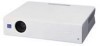
... the =/1 key lights in red. 8 Press the following keys on if the lamp is securely in place. Remove dust from the outside of the used lamp As the used projector lamp in the same way as a fluorescent lamp. Tighten the screws. Disposal of the ventilation holes with a vacuum cleaner. 4 ...Insert the new lamp all the way in until it is not secured properly. 5 Close the lamp cover and tighten the screws....
... the =/1 key lights in red. 8 Press the following keys on if the lamp is securely in place. Remove dust from the outside of the used lamp As the used projector lamp in the same way as a fluorescent lamp. Tighten the screws. Disposal of the ventilation holes with a vacuum cleaner. 4 ...Insert the new lamp all the way in until it is not secured properly. 5 Close the lamp cover and tighten the screws....

Operating Instructions
Page 45
... of focus. c Check that the proper connections have been made (see page 41). menu properly (see page 34). • The lamp has burnt or dims. c Replace the lamp with the power on the screen and press the APA key. The picture is not clear. • Picture is incorrect. •...see page 19). • The sound is set to wrong color system. appears in the INPUT SETTING menu properly (see page 34). • Projector is not adjusted properly. c Adjust the picture (see page 36). The picture is disconnected or the connections are black edges around the image. c ...
... of focus. c Check that the proper connections have been made (see page 41). menu properly (see page 34). • The lamp has burnt or dims. c Replace the lamp with the power on the screen and press the APA key. The picture is not clear. • Picture is incorrect. •...see page 19). • The sound is set to wrong color system. appears in the INPUT SETTING menu properly (see page 34). • Projector is not adjusted properly. c Adjust the picture (see page 36). The picture is disconnected or the connections are black edges around the image. c ...

Operating Instructions
Page 46
... indicator lights up . lights up . • The lamp has reached the end of output to XGA (VPL-CX6/EX1) or SVGA (VPL-CS6) (see page 29). Both the LAMP/COVER • The electrical system breaks down the lamp and turn on the screen. Warning Messages Use the list below to see page...batteries are dead. c Replace with qualified Sony personnel. Others Symptom Cause and Remedy The LAMP/COVER indicator flashes. • The lamp cover or the air filter cover is too high. c Attach the cover securely (see page 48). If it in case of the projector. c Replace the lamp (see page 38). The...
... indicator lights up . lights up . • The lamp has reached the end of output to XGA (VPL-CX6/EX1) or SVGA (VPL-CS6) (see page 29). Both the LAMP/COVER • The electrical system breaks down the lamp and turn on the screen. Warning Messages Use the list below to see page...batteries are dead. c Replace with qualified Sony personnel. Others Symptom Cause and Remedy The LAMP/COVER indicator flashes. • The lamp cover or the air filter cover is too high. c Attach the cover securely (see page 48). If it in case of the projector. c Replace the lamp (see page 38). The...

Operating Instructions
Page 50
...Projector Lamp LMP-C150 (for replacement) (1) Operating Instructions (1) Quick Reference Card (1) Security Label (1) Design and specifications are subject to change without the projection parts) Mass Approx. 2.7 kg (5 lb 15 oz) Power requirements AC 100 to 240 V, 50/60 Hz Power consumption Max. 240 W (Standby mode: VPL-CS6/EX1: 5 W VPL-CX6...your nearest Sony office. 1) VPS-50C may not be available in some areas. B type (1) (1-790-081-31) (VPL-CS6/ CX6 only) CD-ROM (Application software) (VPL-CX6 only) (1) Soft case (1) AC power cord (1) Air filter (for replacement) Signal ...
...Projector Lamp LMP-C150 (for replacement) (1) Operating Instructions (1) Quick Reference Card (1) Security Label (1) Design and specifications are subject to change without the projection parts) Mass Approx. 2.7 kg (5 lb 15 oz) Power requirements AC 100 to 240 V, 50/60 Hz Power consumption Max. 240 W (Standby mode: VPL-CS6/EX1: 5 W VPL-CX6...your nearest Sony office. 1) VPS-50C may not be available in some areas. B type (1) (1-790-081-31) (VPL-CS6/ CX6 only) CD-ROM (Application software) (VPL-CX6 only) (1) Soft case (1) AC power cord (1) Air filter (for replacement) Signal ...
Operating Instructions
Page 54
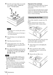
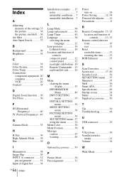
... I Illumination 38 Image Flip 39 INPUT A connector .......12 pin assignment 51 Input-A Signal Sel. .........38 Installation examples ..... 17 notes 7 unsuitable conditions .... 7 unsuitable installation .. 7 L Lamp Mode 39 Lamp replacement .......... 41 Lamp Timer 40 Language 38 selecting the menu language 22 Lens protector 10 Lithium battery 16 Location and function of controls connector panel .......... 12 control...
... I Illumination 38 Image Flip 39 INPUT A connector .......12 pin assignment 51 Input-A Signal Sel. .........38 Installation examples ..... 17 notes 7 unsuitable conditions .... 7 unsuitable installation .. 7 L Lamp Mode 39 Lamp replacement .......... 41 Lamp Timer 40 Language 38 selecting the menu language 22 Lens protector 10 Lithium battery 16 Location and function of controls connector panel .......... 12 control...


