Operating Instructions
Page 2
...CORD, RECEPTACLE OR OTHER OUTLET UNLESS THE BLADES CAN BE FULLY INSERTED TO PREVENT BLADE EXPOSURE. As an ENERGY STAR® partner, Sony Corporation has determined that interference will not occur in accordance with the limits for energy efficiency. "Dolby", "Pro Logic" and the ... the dealer or an experienced radio/TV technician for proper grounding and, in a confined space, such as practical. registered mark. This receiver incorporates Dolby* Digital and Pro Logic Surround and the DTS** Digital Surround System. * Manufactured under license from that any changes or modification...
...CORD, RECEPTACLE OR OTHER OUTLET UNLESS THE BLADES CAN BE FULLY INSERTED TO PREVENT BLADE EXPOSURE. As an ENERGY STAR® partner, Sony Corporation has determined that interference will not occur in accordance with the limits for energy efficiency. "Dolby", "Pro Logic" and the ... the dealer or an experienced radio/TV technician for proper grounding and, in a confined space, such as practical. registered mark. This receiver incorporates Dolby* Digital and Pro Logic Surround and the DTS** Digital Surround System. * Manufactured under license from that any changes or modification...
Operating Instructions
Page 3
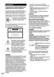
...the display 23 Enjoying Surround Sound Using only the front speakers (2 Channel Stereo 24 Enjoying higher fidelity sound 24 Selecting a sound field 25 Understanding the multi channel surround displays 27 Customizing sound fields 28 Receiving Broadcasts Direct tuning 30 Automatic tuning 31 Preset tuning 31 Other Operations ... sources 33 Recording 33 Using the Sleep Timer 34 Adjustments using the SET UP menu 35 Changing the command mode of the receiver 35 Operations Using the Remote RM-PP412 Before you use your remote 36 Remote button description 36 Selecting the command mode of ...
...the display 23 Enjoying Surround Sound Using only the front speakers (2 Channel Stereo 24 Enjoying higher fidelity sound 24 Selecting a sound field 25 Understanding the multi channel surround displays 27 Customizing sound fields 28 Receiving Broadcasts Direct tuning 30 Automatic tuning 31 Preset tuning 31 Other Operations ... sources 33 Recording 33 Using the Sleep Timer 34 Adjustments using the SET UP menu 35 Changing the command mode of the receiver 35 Operations Using the Remote RM-PP412 Before you use your remote 36 Remote button description 36 Selecting the command mode of ...
Operating Instructions
Page 4
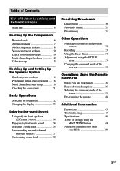
DVD player STR-K850P SS-MSP95 SS-CNP95 SA-WMSP85 DVP-NC665P About area codes The area code of the receiver you purchased is shown on the lower portion of : - For details on the remote are clearly indicated in the text, for the supplied remote RM-... pages 36 - 42. R L CENTER NCE USE 8-16Ω SURROUND 4-XXX-XXX-XX AA Area code Any differences in this manual describe the controls on the receiver. You can also use of area code AA only". Speaker system • Front/surround speakers • Center speaker • Sub woofer - Note for example, "Models...
DVD player STR-K850P SS-MSP95 SS-CNP95 SA-WMSP85 DVP-NC665P About area codes The area code of the receiver you purchased is shown on the lower portion of : - For details on the remote are clearly indicated in the text, for the supplied remote RM-... pages 36 - 42. R L CENTER NCE USE 8-16Ω SURROUND 4-XXX-XXX-XX AA Area code Any differences in this manual describe the controls on the receiver. You can also use of area code AA only". Speaker system • Front/surround speakers • Center speaker • Sub woofer - Note for example, "Models...
Operating Instructions
Page 7
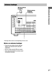
... antenna (supplied) DIGITAL OPTICAL VIDEO 2 IN MD/ TAPE IN MD/ TAPE OUT CD/ SACD IN DVD IN COAXIAL L ANTENNA AM y FM 75Ω COAXIAL L CENTER MONITOR VIDEO IN VIDEO IN VIDEO OUT VIDEO IN VIDEO OUT S-VIDEO S-VIDEO IN IN L S-VIDEO S-VIDEO OUT IN L S-VIDEO OUT... 2 VIDEO 1 WOOFER * * The shape of the connector varies depending on antenna hookups • To prevent noise pickup, keep the AM loop antenna away from the receiver and other components. • Be sure to fully extend the FM wire antenna. • After connecting the FM wire antenna, keep it as horizontal as possible. 7US
... antenna (supplied) DIGITAL OPTICAL VIDEO 2 IN MD/ TAPE IN MD/ TAPE OUT CD/ SACD IN DVD IN COAXIAL L ANTENNA AM y FM 75Ω COAXIAL L CENTER MONITOR VIDEO IN VIDEO IN VIDEO OUT VIDEO IN VIDEO OUT S-VIDEO S-VIDEO IN IN L S-VIDEO S-VIDEO OUT IN L S-VIDEO OUT... 2 VIDEO 1 WOOFER * * The shape of the connector varies depending on antenna hookups • To prevent noise pickup, keep the AM loop antenna away from the receiver and other components. • Be sure to fully extend the FM wire antenna. • After connecting the FM wire antenna, keep it as horizontal as possible. 7US
Operating Instructions
Page 9
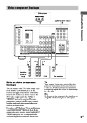
...via an S-video jack. S-video signals are not compatible with COMPONENT VIDEO input jacks, use a component video cord (not supplied) to connect to the receiver as shown above. Hooking Up the Components Ç Ç Video component hookups DVD player OUTPUT AUDIO OUT R L VIDEO OUT B COMPONENT VIDEO H DIGITAL... OPTICAL VIDEO 2 IN MD/ TAPE IN MD/ TAPE OUT CD/ SACD IN DVD IN COAXIAL L ANTENNA AM y FM 75Ω COAXIAL L CENTER MONITOR VIDEO IN VIDEO IN VIDEO OUT VIDEO IN VIDEO OUT S-VIDEO S-VIDEO IN IN L S-VIDEO S-VIDEO OUT IN L S-...
...via an S-video jack. S-video signals are not compatible with COMPONENT VIDEO input jacks, use a component video cord (not supplied) to connect to the receiver as shown above. Hooking Up the Components Ç Ç Video component hookups DVD player OUTPUT AUDIO OUT R L VIDEO OUT B COMPONENT VIDEO H DIGITAL... OPTICAL VIDEO 2 IN MD/ TAPE IN MD/ TAPE OUT CD/ SACD IN DVD IN COAXIAL L ANTENNA AM y FM 75Ω COAXIAL L CENTER MONITOR VIDEO IN VIDEO IN VIDEO OUT VIDEO IN VIDEO OUT S-VIDEO S-VIDEO IN IN L S-VIDEO S-VIDEO OUT IN L S-...
Operating Instructions
Page 10
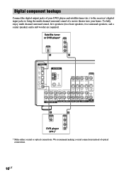
... VIDEO OUT OUTPUT DIGITAL OPTICAL AUDIO OUT L R E B DIGITAL OPTICAL VIDEO 2 IN MD/ TAPE IN MD/ TAPE OUT CD/ SACD IN DVD IN COAXIAL L ANTENNA AM y FM 75Ω COAXIAL L CENTER MONITOR VIDEO IN VIDEO IN VIDEO OUT VIDEO IN VIDEO OUT S-VIDEO S-VIDEO IN IN L S-VIDEO S-VIDEO OUT IN L S-VIDEO OUT... instead of a movie theater into your home. Digital component hookups Connect the digital output jacks of your DVD player and satellite tuner (etc.) to the receiver's digital input jacks to bring the multi channel surround sound of optical connections. 10US
... VIDEO OUT OUTPUT DIGITAL OPTICAL AUDIO OUT L R E B DIGITAL OPTICAL VIDEO 2 IN MD/ TAPE IN MD/ TAPE OUT CD/ SACD IN DVD IN COAXIAL L ANTENNA AM y FM 75Ω COAXIAL L CENTER MONITOR VIDEO IN VIDEO IN VIDEO OUT VIDEO IN VIDEO OUT S-VIDEO S-VIDEO IN IN L S-VIDEO S-VIDEO OUT IN L S-VIDEO OUT... instead of a movie theater into your home. Digital component hookups Connect the digital output jacks of your DVD player and satellite tuner (etc.) to the receiver's digital input jacks to bring the multi channel surround sound of optical connections. 10US
Operating Instructions
Page 11
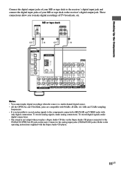
... R E OUT E IN A OUT A IN ç ç DIGITAL OPTICAL VIDEO 2 IN MD/ TAPE IN MD/ TAPE OUT CD/ SACD IN DVD IN COAXIAL L ANTENNA AM y FM 75Ω COAXIAL L CENTER MONITOR VIDEO IN VIDEO IN VIDEO OUT VIDEO IN VIDEO OUT S-VIDEO S-VIDEO IN IN L S-VIDEO S-VIDEO OUT IN L S-VIDEO OUT... to MD/TAPE and VIDEO jacks with only digital connections. To record analog signals, make digital recordings of your MD or tape deck to the receiver's digital input jack and connect the digital input jacks of TV broadcasts, etc. To record digital signals, make digital recordings when the source is...
... R E OUT E IN A OUT A IN ç ç DIGITAL OPTICAL VIDEO 2 IN MD/ TAPE IN MD/ TAPE OUT CD/ SACD IN DVD IN COAXIAL L ANTENNA AM y FM 75Ω COAXIAL L CENTER MONITOR VIDEO IN VIDEO IN VIDEO OUT VIDEO IN VIDEO OUT S-VIDEO S-VIDEO IN IN L S-VIDEO S-VIDEO OUT IN L S-VIDEO OUT... to MD/TAPE and VIDEO jacks with only digital connections. To record analog signals, make digital recordings of your MD or tape deck to the receiver's digital input jack and connect the digital input jacks of TV broadcasts, etc. To record digital signals, make digital recordings when the source is...
Operating Instructions
Page 12
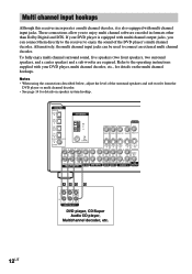
...the DVD player's multi channel decoder. DIGITAL OPTICAL VIDEO 2 IN MD/ TAPE IN MD/ TAPE OUT CD/ SACD IN DVD IN COAXIAL L ANTENNA AM y FM 75Ω COAXIAL L CENTER MONITOR VIDEO IN VIDEO IN VIDEO OUT VIDEO IN VIDEO OUT S-VIDEO S-VIDEO IN IN L S-VIDEO S-VIDEO OUT IN L S-...is also equipped with your DVD player, multi channel decoder, etc., for details on the multi channel hookups. Multi channel input hookups Although this receiver incorporates a multi channel decoder, it is equipped with multi channel output jacks, you to enjoy multi channel software encoded in formats other than ...
...the DVD player's multi channel decoder. DIGITAL OPTICAL VIDEO 2 IN MD/ TAPE IN MD/ TAPE OUT CD/ SACD IN DVD IN COAXIAL L ANTENNA AM y FM 75Ω COAXIAL L CENTER MONITOR VIDEO IN VIDEO IN VIDEO OUT VIDEO IN VIDEO OUT S-VIDEO S-VIDEO IN IN L S-VIDEO S-VIDEO OUT IN L S-...is also equipped with your DVD player, multi channel decoder, etc., for details on the multi channel hookups. Multi channel input hookups Although this receiver incorporates a multi channel decoder, it is equipped with multi channel output jacks, you to enjoy multi channel software encoded in formats other than ...
Operating Instructions
Page 13
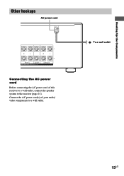
Connect the AC power cord(s) of this receiver to a wall outlet, connect the speaker system to a wall outlet. Hooking Up the Components Other hookups AC power cord R L R L FRONT A CENTER SPEAKERS IMPEDANCE USE 8-16Ω SURROUND Connecting the AC power cord Before connecting the AC power cord of your audio/ video components to the receiver (page 14). b To a wall outlet 13US
Connect the AC power cord(s) of this receiver to a wall outlet, connect the speaker system to a wall outlet. Hooking Up the Components Other hookups AC power cord R L R L FRONT A CENTER SPEAKERS IMPEDANCE USE 8-16Ω SURROUND Connecting the AC power cord Before connecting the AC power cord of your audio/ video components to the receiver (page 14). b To a wall outlet 13US
Operating Instructions
Page 15
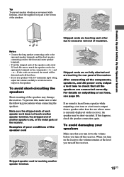
...speaker cord Stripped cords are not fully attached and are reversed, the sound will lack bass. • If you turn off the receiver. After connecting all the speakers are touching each speaker cord does not touch another speaker terminal, the stripped end of the speakers.... Examples of poor conditions of the receiver. Stripped speaker cord is output from a speaker other due to take the following precautions when connecting the speakers. Notes • Connect...
...speaker cord Stripped cords are not fully attached and are reversed, the sound will lack bass. • If you turn off the receiver. After connecting all the speakers are touching each speaker cord does not touch another speaker terminal, the stripped end of the speakers.... Examples of poor conditions of the receiver. Stripped speaker cord is output from a speaker other due to take the following precautions when connecting the speakers. Notes • Connect...
Operating Instructions
Page 16
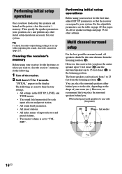
....) and perform any other settings. Tip To check the audio output during settings (to set to "VOL MIN". Clearing the receiver's memory Before using your receiver for each input selector and preset station. • All sound field parameters. • All preset stations. • All ...initial setup operations necessary for 5 seconds. You can be the same distance from the listening position (A). The following . 1 Turn off the receiver. 2 Hold down ?/1 for your system. Multi channel surround setup For the best possible surround sound, all speakers should be placed from 3...
....) and perform any other settings. Tip To check the audio output during settings (to set to "VOL MIN". Clearing the receiver's memory Before using your receiver for each input selector and preset station. • All sound field parameters. • All preset stations. • All ...initial setup operations necessary for 5 seconds. You can be the same distance from the listening position (A). The following . 1 Turn off the receiver. 2 Hold down ?/1 for your system. Multi channel surround setup For the best possible surround sound, all speakers should be placed from 3...
Operating Instructions
Page 18
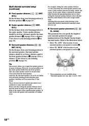
... front speakers. LOW" if the location of your listening position to input the speaker position in the output of being "inside" the screen. Tip The receiver allows you cannot obtain a satisfactory surround effect because the surround speakers are not available when "Surround speaker size ( SL SR )" is not possible to set...
... front speakers. LOW" if the location of your listening position to input the speaker position in the output of being "inside" the screen. Tip The receiver allows you cannot obtain a satisfactory surround effect because the surround speakers are not available when "Surround speaker size ( SL SR )" is not possible to set...
Operating Instructions
Page 20
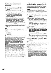
... recommend you follow the procedure described above and adjust the speaker levels from your listening position to adjust the level of each speaker. Note The receiver incorporates a new test tone with a frequency centered at the same time. Front (left) t Center t Front (right) t Surround (right) t Surround (left...the test tone is output from the speaker whose adjustment is best not to the following Dolby Pro Logic modes *1 NORMAL *2 PHANTOM *3 3 STEREO Tip Internally, the LARGE and SMALL settings for easier speaker level adjustment. 1 Press ?/1 on the remote to turn MASTER VOLUME on the ...
... recommend you follow the procedure described above and adjust the speaker levels from your listening position to adjust the level of each speaker. Note The receiver incorporates a new test tone with a frequency centered at the same time. Front (left) t Center t Front (right) t Surround (right) t Surround (left...the test tone is output from the speaker whose adjustment is best not to the following Dolby Pro Logic modes *1 NORMAL *2 PHANTOM *3 3 STEREO Tip Internally, the LARGE and SMALL settings for easier speaker level adjustment. 1 Press ?/1 on the remote to turn MASTER VOLUME on the ...
Operating Instructions
Page 21
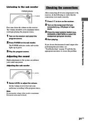
... to maximum. Set the volume level to best suit your sound enjoyment. Note Do not turn the volume of your components to the receiver, do not obtain normal sound output after performing this procedure, see "Troubleshooting" on page 43 and take the appropriate measures to correct the...TAPE) to adjust the volume. Hooking Up and Setting Up the Speaker System Listening to the sub woofer POWER indicator POWER First, turn on the receiver. 2 Turn on the component that the connections were made correctly. 1 Press ?/1 to the program source. Adjusting the sound Slight adjustments to ...
... to maximum. Set the volume level to best suit your sound enjoyment. Note Do not turn the volume of your components to the receiver, do not obtain normal sound output after performing this procedure, see "Troubleshooting" on page 43 and take the appropriate measures to correct the...TAPE) to adjust the volume. Hooking Up and Setting Up the Speaker System Listening to the sub woofer POWER indicator POWER First, turn on the receiver. 2 Turn on the component that the connections were made correctly. 1 Press ?/1 to the program source. Adjusting the sound Slight adjustments to ...
Operating Instructions
Page 24
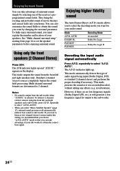
...lights up and "2CH ST." This mode automatically detects the type of audio signal being input (Dolby Digital, DTS, or standard 2 channel stereo) and performs the proper decoding if necessary. You can take advantage of surround sound simply by changing the surround parameter. The 2CH indicator lights ...under this setting, we recommend that you can also customize the sound fields to obtain the sound you want by selecting one of the receiver's preprogrammed sound fields. Multi channel surround formats are no low frequency signals (Dolby Digital LFE, etc.) it was recorded/encoded, without ...
...lights up and "2CH ST." This mode automatically detects the type of audio signal being input (Dolby Digital, DTS, or standard 2 channel stereo) and performs the proper decoding if necessary. You can take advantage of surround sound simply by changing the surround parameter. The 2CH indicator lights ...under this setting, we recommend that you can also customize the sound fields to obtain the sound you want by selecting one of the receiver's preprogrammed sound fields. Multi channel surround formats are no low frequency signals (Dolby Digital LFE, etc.) it was recorded/encoded, without ...
Operating Instructions
Page 25
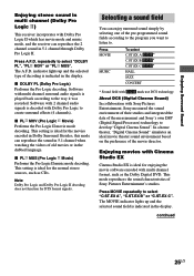
...Entertainment, Sony measured the sound environment of their studios and integrated the data of the pre-programmed sound fields according to the program you want to listen to the way it was recorded. Enjoying Surround Sound Enjoying stereo sound in multi channel (Dolby Pro Logic ) This receiver incorporates... with Dolby Pro Logic II which has movie mode and music mode, and the receiver can reproduce the 2 channel sound in Dolby Surround. Press MOVIE...
...Entertainment, Sony measured the sound environment of their studios and integrated the data of the pre-programmed sound fields according to the program you want to listen to the way it was recorded. Enjoying Surround Sound Enjoying stereo sound in multi channel (Dolby Pro Logic ) This receiver incorporates... with Dolby Pro Logic II which has movie mode and music mode, and the receiver can reproduce the 2 channel sound in Dolby Surround. Press MOVIE...
Operating Instructions
Page 26
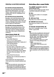
...is featured in the soundtrack. x CONCERT (Live Concert) Reproduces the acoustics of the Sony Pictures Entertainment "Cary Grant Theater" cinema production studio. Tips • The receiver lets you apply the last selected sound field to select "A.F.D. This mode is ideal ...for watching musicals or classic films where music is the integrated mode which operates these elements simultaneously. Notes • The effects provided by the virtual speakers may cause increased noise in stereo...
...is featured in the soundtrack. x CONCERT (Live Concert) Reproduces the acoustics of the Sony Pictures Entertainment "Cary Grant Theater" cinema production studio. Tips • The receiver lets you apply the last selected sound field to select "A.F.D. This mode is ideal ...for watching musicals or classic films where music is the integrated mode which operates these elements simultaneously. Notes • The effects provided by the virtual speakers may cause increased noise in stereo...
Operating Instructions
Page 27
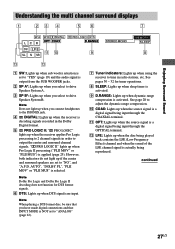
...Pro Logic II decoding does not function for tuner operations. 8 SLEEP: Lights up when sleep timer is activated. 9 D.RANGE: Lights up when the receiver is decoding signals recorded in radio stations, etc. See page 28 to adjust the dynamic range compression. 0 COAX: Lights up when DTS signals are...Understanding the multi channel surround displays 1 23 4 56 7 SP A SP B aDIGITAL a PRO LOGIC II DTS L C R OPT COAX D.RANGE SW L F E qa q; 9 SL S SR STEREO MONO MEMORY SLEEP 8 qd qs 1 SW: Lights up when sub woofer selection is set to "YES" (page 19) and the audio signal is output from...
...Pro Logic II decoding does not function for tuner operations. 8 SLEEP: Lights up when sleep timer is activated. 9 D.RANGE: Lights up when the receiver is decoding signals recorded in radio stations, etc. See page 28 to adjust the dynamic range compression. 0 COAX: Lights up when DTS signals are...Understanding the multi channel surround displays 1 23 4 56 7 SP A SP B aDIGITAL a PRO LOGIC II DTS L C R OPT COAX D.RANGE SW L F E qa q; 9 SL S SR STEREO MONO MEMORY SLEEP 8 qd qs 1 SW: Lights up when sub woofer selection is set to "YES" (page 19) and the audio signal is output from...
Operating Instructions
Page 28
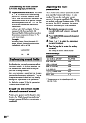
....) indicate the channels being played back. The boxes around the letters vary to the parameters. When using sound fields like "C.ST.EX", the receiver adds reverberation based on the speakers settings). L (Front Left), R (Front Right), C (Center (monaural)), SL (Surround Left), SR (...Surround Right), S (Surround (monaural or the surround components obtained by making new adjustments to show how the receiver downmixes the source sound (based on the source sound. parameter. The setting is entered automatically. Initial settings Parameter L R BAL. L/R XX...
....) indicate the channels being played back. The boxes around the letters vary to the parameters. When using sound fields like "C.ST.EX", the receiver adds reverberation based on the speakers settings). L (Front Left), R (Front Right), C (Center (monaural)), SL (Surround Left), SR (...Surround Right), S (Surround (monaural or the surround components obtained by making new adjustments to show how the receiver downmixes the source sound (based on the source sound. parameter. The setting is entered automatically. Initial settings Parameter L R BAL. L/R XX...
Operating Instructions
Page 30
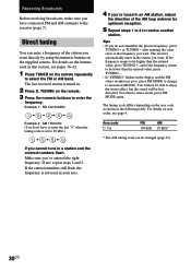
after entering the value close to stereo mode, press FM MODE again. To return to the frequency you want. The last received station is poor, press FM MODE to change to be lower than the entered value, press TUNING +, and if the frequency seems to monaural (MONO). If not, ...FM stereo reception is tuned in. 2 Press D. Example 1: FM 102.50 MHz 1 b0 b2 b5b 0 Example 2: AM 1350 kHz (You don't have connected FM and AM antennas to enter the frequency. Tips • If you want directly by using the numeric buttons on the remote. 3 Press the numeric buttons to the receiver...
after entering the value close to stereo mode, press FM MODE again. To return to the frequency you want. The last received station is poor, press FM MODE to change to be lower than the entered value, press TUNING +, and if the frequency seems to monaural (MONO). If not, ...FM stereo reception is tuned in. 2 Press D. Example 1: FM 102.50 MHz 1 b0 b2 b5b 0 Example 2: AM 1350 kHz (You don't have connected FM and AM antennas to enter the frequency. Tips • If you want directly by using the numeric buttons on the remote. 3 Press the numeric buttons to the receiver...


