
Limited Warranty (U.S. Only)
Page 1
... of incidental or consequential damages, or allow limitations on how long an implied warranty lasts does not apply to any authorized Sony service facility. EXCEPT TO THE EXTENT PROHIBITED BY APPLICABLE LAW, ANY IMPLIED WARRANTY OF MERCHANTABILITY OR FITNESS FOR A PARTICULAR PURPOSE...ON THIS PRODUCT. 4-557-173-02 General Stereo/Hifi Components/Tape Decks ® CD Players/Mini Disc Players/Audio Systems Hifi Audio LIMITED WARRANTY Sony Electronics Inc. ("Sony") warrants this Product is determined to be presented to any Sony authorized service facility. After the Warranty Period...
... of incidental or consequential damages, or allow limitations on how long an implied warranty lasts does not apply to any authorized Sony service facility. EXCEPT TO THE EXTENT PROHIBITED BY APPLICABLE LAW, ANY IMPLIED WARRANTY OF MERCHANTABILITY OR FITNESS FOR A PARTICULAR PURPOSE...ON THIS PRODUCT. 4-557-173-02 General Stereo/Hifi Components/Tape Decks ® CD Players/Mini Disc Players/Audio Systems Hifi Audio LIMITED WARRANTY Sony Electronics Inc. ("Sony") warrants this Product is determined to be presented to any Sony authorized service facility. After the Warranty Period...
Operating Instructions
Page 1
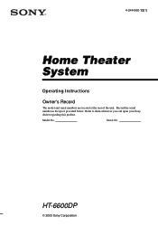
Serial No. 4-244-560-12(1) Home Theater System Operating Instructions Owner's Record The model and serial numbers are located at the rear of the unit. HT-6600DP © 2003 Sony Corporation Record the serial number in the space provided below. Refer to them whenever you call upon your Sony dealer regarding this product. Model No.
Serial No. 4-244-560-12(1) Home Theater System Operating Instructions Owner's Record The model and serial numbers are located at the rear of the unit. HT-6600DP © 2003 Sony Corporation Record the serial number in the space provided below. Refer to them whenever you call upon your Sony dealer regarding this product. Model No.
Operating Instructions
Page 2
... any changes or modification not expressly approved in this equipment does cause harmful interference to radio or television reception, which the receiver is provided to call CATV system installer's attention to Article 820-40 of the NEC that the cable ground shall be ..., curtains, etc. As an ENERGY STAR® partner, Sony Corporation has determined that this equipment. Note to CATV system installer: This reminder is connected. - Increase the separation between the equipment and receiver. - Reorient or relocate the receiving antenna. - ENERGY STAR® is no guarantee that to...
... any changes or modification not expressly approved in this equipment does cause harmful interference to radio or television reception, which the receiver is provided to call CATV system installer's attention to Article 820-40 of the NEC that the cable ground shall be ..., curtains, etc. As an ENERGY STAR® partner, Sony Corporation has determined that this equipment. Note to CATV system installer: This reminder is connected. - Increase the separation between the equipment and receiver. - Reorient or relocate the receiving antenna. - ENERGY STAR® is no guarantee that to...
Operating Instructions
Page 3
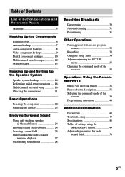
...the display 23 Enjoying Surround Sound Using only the front speakers (2 Channel Stereo 24 Enjoying higher fidelity sound 24 Selecting a sound field 25 Understanding the multi channel surround displays 27 Customizing sound fields 28 Receiving Broadcasts Direct tuning 30 Automatic tuning 31 Preset tuning 31 Other Operations ... sources 33 Recording 33 Using the Sleep Timer 34 Adjustments using the SET UP menu 35 Changing the command mode of the receiver 35 Operations Using the Remote RM-PP412 Before you use your remote 36 Remote button description 36 Selecting the command mode of ...
...the display 23 Enjoying Surround Sound Using only the front speakers (2 Channel Stereo 24 Enjoying higher fidelity sound 24 Selecting a sound field 25 Understanding the multi channel surround displays 27 Customizing sound fields 28 Receiving Broadcasts Direct tuning 30 Automatic tuning 31 Preset tuning 31 Other Operations ... sources 33 Recording 33 Using the Sleep Timer 34 Adjustments using the SET UP menu 35 Changing the command mode of the receiver 35 Operations Using the Remote RM-PP412 Before you use your remote 36 Remote button description 36 Selecting the command mode of ...
Operating Instructions
Page 4
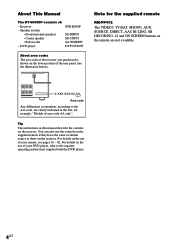
DVD player STR-K850P SS-MSP95 SS-CNP95 SA-WMSP85 DVP-NC665P About area codes The area code of the receiver you purchased is shown on the receiver. Tip The instructions in the text, for the supplied remote RM-PP412 The VIDEO3, TV/SAT, PHONO, AUX, SOURCE, DIRECT, AAC BI-LING, SB ... if they have the same or similar names as those on the use of your DVD player, refer to the area code, are not available. Receiver - Speaker system • Front/surround speakers • Center speaker • Sub woofer - R L CENTER NCE USE 8-16Ω SURROUND 4-XXX-XXX-XX AA Area ...
DVD player STR-K850P SS-MSP95 SS-CNP95 SA-WMSP85 DVP-NC665P About area codes The area code of the receiver you purchased is shown on the receiver. Tip The instructions in the text, for the supplied remote RM-PP412 The VIDEO3, TV/SAT, PHONO, AUX, SOURCE, DIRECT, AAC BI-LING, SB ... if they have the same or similar names as those on the use of your DVD player, refer to the area code, are not available. Receiver - Speaker system • Front/surround speakers • Center speaker • Sub woofer - R L CENTER NCE USE 8-16Ω SURROUND 4-XXX-XXX-XX AA Area ...
Operating Instructions
Page 5
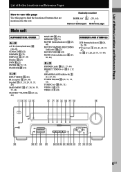
... (30) I - Illustration number r DISPLAY 3 (23, 45) R R Name of buttons that are mentioned in the text. wg (31, 32 47) SPEAKERS (OFF/A/B/A+B) 2 (14, 23, 44) TUNER FM/AM qa (22, 31, 32, 33) TUNING +/- List of Button Locations and Reference Pages List of Button Locations and Reference Pages How to use this...
... (30) I - Illustration number r DISPLAY 3 (23, 45) R R Name of buttons that are mentioned in the text. wg (31, 32 47) SPEAKERS (OFF/A/B/A+B) 2 (14, 23, 44) TUNER FM/AM qa (22, 31, 32, 33) TUNING +/- List of Button Locations and Reference Pages List of Button Locations and Reference Pages How to use this...
Operating Instructions
Page 6
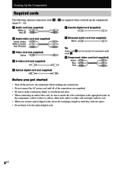
and red (right, audio) to white; Hooking Up the Components Required cords The following optional connection cords A - white (left, audio) to red. • When you hook up the components (pages 8 - 12). H are completed. • Be sure to make connections firmly to avoid hum and noise. • When connecting an audio/video cord, be torn into place. • Do not bend or tie the optical digital cord. 6US A Audio cord (not supplied) White (L) Red (R) F Coaxial digital cord (supplied) B Audio/video cord (not supplied) Yellow (video) White (L/audio) Red (R/audio) C Video ...
and red (right, audio) to white; Hooking Up the Components Required cords The following optional connection cords A - white (left, audio) to red. • When you hook up the components (pages 8 - 12). H are completed. • Be sure to make connections firmly to avoid hum and noise. • When connecting an audio/video cord, be torn into place. • Do not bend or tie the optical digital cord. 6US A Audio cord (not supplied) White (L) Red (R) F Coaxial digital cord (supplied) B Audio/video cord (not supplied) Yellow (video) White (L/audio) Red (R/audio) C Video ...
Operating Instructions
Page 7
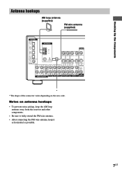
... antenna (supplied) DIGITAL OPTICAL VIDEO 2 IN MD/ TAPE IN MD/ TAPE OUT CD/ SACD IN DVD IN COAXIAL L ANTENNA AM y FM 75Ω COAXIAL L CENTER MONITOR VIDEO IN VIDEO IN VIDEO OUT VIDEO IN VIDEO OUT S-VIDEO S-VIDEO IN IN L S-VIDEO S-VIDEO OUT IN L S-VIDEO ...2 VIDEO 1 WOOFER * * The shape of the connector varies depending on antenna hookups • To prevent noise pickup, keep the AM loop antenna away from the receiver and other components. • Be sure to fully extend the FM wire antenna. • After connecting the FM wire antenna, keep it as horizontal as possible. 7US
... antenna (supplied) DIGITAL OPTICAL VIDEO 2 IN MD/ TAPE IN MD/ TAPE OUT CD/ SACD IN DVD IN COAXIAL L ANTENNA AM y FM 75Ω COAXIAL L CENTER MONITOR VIDEO IN VIDEO IN VIDEO OUT VIDEO IN VIDEO OUT S-VIDEO S-VIDEO IN IN L S-VIDEO S-VIDEO OUT IN L S-VIDEO ...2 VIDEO 1 WOOFER * * The shape of the connector varies depending on antenna hookups • To prevent noise pickup, keep the AM loop antenna away from the receiver and other components. • Be sure to fully extend the FM wire antenna. • After connecting the FM wire antenna, keep it as horizontal as possible. 7US
Operating Instructions
Page 8
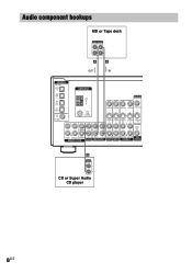
Audio component hookups MD or Tape deck INPUT OUTPUT LINE LINE L R A A OUT IN ç ç DIGITAL OPTICAL VIDEO 2 IN MD/ TAPE IN MD/ TAPE OUT CD/ SACD IN DVD IN COAXIAL L ANTENNA AM y FM 75Ω COAXIAL L CENTER MONITOR VIDEO IN VIDEO IN VIDEO OUT VIDEO IN VIDEO OUT S-VIDEO S-VIDEO IN IN L S-VIDEO S-VIDEO OUT IN L S-VIDEO OUT AUDIO OUT R R SUB FRONT SURROUND WOOFER MULTI CH IN IN CD/SACD OUT IN MD/TAPE R R AUDIO IN AUDIO IN AUDIO OUT AUDIO IN SUB DVD VIDEO 2 VIDEO 1 WOOFER A OUTPUT LINE L R CD or Super Audio CD player 8US
Audio component hookups MD or Tape deck INPUT OUTPUT LINE LINE L R A A OUT IN ç ç DIGITAL OPTICAL VIDEO 2 IN MD/ TAPE IN MD/ TAPE OUT CD/ SACD IN DVD IN COAXIAL L ANTENNA AM y FM 75Ω COAXIAL L CENTER MONITOR VIDEO IN VIDEO IN VIDEO OUT VIDEO IN VIDEO OUT S-VIDEO S-VIDEO IN IN L S-VIDEO S-VIDEO OUT IN L S-VIDEO OUT AUDIO OUT R R SUB FRONT SURROUND WOOFER MULTI CH IN IN CD/SACD OUT IN MD/TAPE R R AUDIO IN AUDIO IN AUDIO OUT AUDIO IN SUB DVD VIDEO 2 VIDEO 1 WOOFER A OUTPUT LINE L R CD or Super Audio CD player 8US
Operating Instructions
Page 9
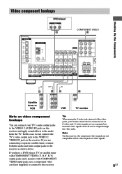
...signals are not compatible with COMPONENT VIDEO input jacks, use a component video cord (not supplied) to connect to the VIDEO 2 VIDEO IN jack on the receiver. Hooking Up the Components Ç Ç Video component hookups DVD player OUTPUT AUDIO OUT R L VIDEO OUT B COMPONENT VIDEO H DIGITAL OPTICAL VIDEO ...2 IN MD/ TAPE IN MD/ TAPE OUT CD/ SACD IN DVD IN COAXIAL L ANTENNA AM y FM 75Ω COAXIAL L CENTER MONITOR VIDEO IN VIDEO IN VIDEO OUT VIDEO IN VIDEO OUT S-VIDEO S-VIDEO IN IN L S-VIDEO S-VIDEO OUT IN L S-...
...signals are not compatible with COMPONENT VIDEO input jacks, use a component video cord (not supplied) to connect to the VIDEO 2 VIDEO IN jack on the receiver. Hooking Up the Components Ç Ç Video component hookups DVD player OUTPUT AUDIO OUT R L VIDEO OUT B COMPONENT VIDEO H DIGITAL OPTICAL VIDEO ...2 IN MD/ TAPE IN MD/ TAPE OUT CD/ SACD IN DVD IN COAXIAL L ANTENNA AM y FM 75Ω COAXIAL L CENTER MONITOR VIDEO IN VIDEO IN VIDEO OUT VIDEO IN VIDEO OUT S-VIDEO S-VIDEO IN IN L S-VIDEO S-VIDEO OUT IN L S-...
Operating Instructions
Page 10
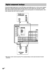
...DIGITAL OPTICAL AUDIO OUT L R E B DIGITAL OPTICAL VIDEO 2 IN MD/ TAPE IN MD/ TAPE OUT CD/ SACD IN DVD IN COAXIAL L ANTENNA AM y FM 75Ω COAXIAL L CENTER MONITOR VIDEO IN VIDEO IN VIDEO OUT VIDEO IN VIDEO OUT S-VIDEO S-VIDEO IN IN L S-VIDEO S-VIDEO OUT IN L S-VIDEO ...a movie theater into your home. Digital component hookups Connect the digital output jacks of your DVD player and satellite tuner (etc.) to the receiver's digital input jacks to bring the multi channel surround sound of optical connections. 10US To fully enjoy multi channel surround sound, five speakers (two...
...DIGITAL OPTICAL AUDIO OUT L R E B DIGITAL OPTICAL VIDEO 2 IN MD/ TAPE IN MD/ TAPE OUT CD/ SACD IN DVD IN COAXIAL L ANTENNA AM y FM 75Ω COAXIAL L CENTER MONITOR VIDEO IN VIDEO IN VIDEO OUT VIDEO IN VIDEO OUT S-VIDEO S-VIDEO IN IN L S-VIDEO S-VIDEO OUT IN L S-VIDEO ...a movie theater into your home. Digital component hookups Connect the digital output jacks of your DVD player and satellite tuner (etc.) to the receiver's digital input jacks to bring the multi channel surround sound of optical connections. 10US To fully enjoy multi channel surround sound, five speakers (two...
Operating Instructions
Page 11
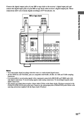
... Audio CD player connected to make digital connections. • The sound is not possible to record analog signals to the components connected to the receiver's digital output jack. To record digital signals, make digital recordings of your MD or tape deck to MD/TAPE and VIDEO jacks with only ...L R E OUT E IN A OUT A IN ç ç DIGITAL OPTICAL VIDEO 2 IN MD/ TAPE IN MD/ TAPE OUT CD/ SACD IN DVD IN COAXIAL L ANTENNA AM y FM 75Ω COAXIAL L CENTER MONITOR VIDEO IN VIDEO IN VIDEO OUT VIDEO IN VIDEO OUT S-VIDEO S-VIDEO IN IN L S-VIDEO S-VIDEO OUT IN L S-VIDEO OUT...
... Audio CD player connected to make digital connections. • The sound is not possible to record analog signals to the components connected to the receiver's digital output jack. To record digital signals, make digital recordings of your MD or tape deck to MD/TAPE and VIDEO jacks with only ...L R E OUT E IN A OUT A IN ç ç DIGITAL OPTICAL VIDEO 2 IN MD/ TAPE IN MD/ TAPE OUT CD/ SACD IN DVD IN COAXIAL L ANTENNA AM y FM 75Ω COAXIAL L CENTER MONITOR VIDEO IN VIDEO IN VIDEO OUT VIDEO IN VIDEO OUT S-VIDEO S-VIDEO IN IN L S-VIDEO S-VIDEO OUT IN L S-VIDEO OUT...
Operating Instructions
Page 12
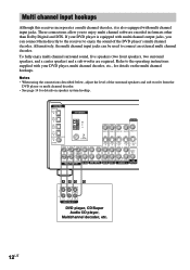
...speakers, two surround speakers, and a center speaker) and a sub woofer are required. Alternatively, the multi channel input jacks can connect them directly to the receiver to enjoy multi channel software encoded in formats other than Dolby Digital and DTS. DIGITAL OPTICAL VIDEO 2 IN MD/ TAPE IN MD/ TAPE OUT CD.../ SACD IN DVD IN COAXIAL L ANTENNA AM y FM 75Ω COAXIAL L CENTER MONITOR VIDEO IN VIDEO IN VIDEO OUT VIDEO IN VIDEO OUT S-VIDEO S-VIDEO IN IN L S-VIDEO S-VIDEO OUT IN L S-...
...speakers, two surround speakers, and a center speaker) and a sub woofer are required. Alternatively, the multi channel input jacks can connect them directly to the receiver to enjoy multi channel software encoded in formats other than Dolby Digital and DTS. DIGITAL OPTICAL VIDEO 2 IN MD/ TAPE IN MD/ TAPE OUT CD.../ SACD IN DVD IN COAXIAL L ANTENNA AM y FM 75Ω COAXIAL L CENTER MONITOR VIDEO IN VIDEO IN VIDEO OUT VIDEO IN VIDEO OUT S-VIDEO S-VIDEO IN IN L S-VIDEO S-VIDEO OUT IN L S-...
Operating Instructions
Page 13
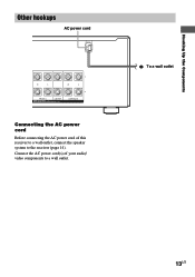
Connect the AC power cord(s) of this receiver to a wall outlet, connect the speaker system to a wall outlet. Hooking Up the Components Other hookups AC power cord R L R L FRONT A CENTER SPEAKERS IMPEDANCE USE 8-16Ω SURROUND Connecting the AC power cord Before connecting the AC power cord of your audio/ video components to the receiver (page 14). b To a wall outlet 13US
Connect the AC power cord(s) of this receiver to a wall outlet, connect the speaker system to a wall outlet. Hooking Up the Components Other hookups AC power cord R L R L FRONT A CENTER SPEAKERS IMPEDANCE USE 8-16Ω SURROUND Connecting the AC power cord Before connecting the AC power cord of your audio/ video components to the receiver (page 14). b To a wall outlet 13US
Operating Instructions
Page 14
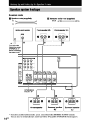
You can select the front speakers you have an additional front speaker system, connect them to use with the SPEAKERS (OFF/A/B/A+B) button (page 23). 14US Hooking Up and Setting Up the Speaker System Speaker system hookups Required cords A Speaker cords (supplied) (+) (-) B Monaural audio cord (supplied) Black Active sub woofer INPUT AUDIO IN Front speaker (R) Front speaker (L) e Ee E b B To a wall outlet (Switch the power (POWER) to off before connecting the power cord.) A A COMPONENT VIDEO Y MONITOR PB/B-Y VIDEO OUT PR/R-Y DVD VIDEO 2 MONITOR IN IN OUT S-VIDEO OUT ...
You can select the front speakers you have an additional front speaker system, connect them to use with the SPEAKERS (OFF/A/B/A+B) button (page 23). 14US Hooking Up and Setting Up the Speaker System Speaker system hookups Required cords A Speaker cords (supplied) (+) (-) B Monaural audio cord (supplied) Black Active sub woofer INPUT AUDIO IN Front speaker (R) Front speaker (L) e Ee E b B To a wall outlet (Switch the power (POWER) to off before connecting the power cord.) A A COMPONENT VIDEO Y MONITOR PB/B-Y VIDEO OUT PR/R-Y DVD VIDEO 2 MONITOR IN IN OUT S-VIDEO OUT ...
Operating Instructions
Page 15
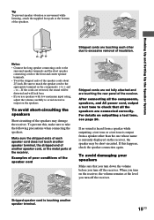
...speaker cord, or the metal parts of insulation. Stripped speaker cord is output from a speaker other due to avoid excessive output on the receiver, the volume remains at the bottom of the speakers. Hooking Up and Setting Up the Speaker System Stripped cords are touching the rear ...speaker cord Stripped cords are not fully attached and are touching each speaker cord does not touch another speaker terminal, the stripped end of the receiver. Make sure the stripped ends of the speaker cords about 2/3 inch. For details on the components: + to take the following precautions when...
...speaker cord, or the metal parts of insulation. Stripped speaker cord is output from a speaker other due to avoid excessive output on the receiver, the volume remains at the bottom of the speakers. Hooking Up and Setting Up the Speaker System Stripped cords are touching the rear ...speaker cord Stripped cords are not fully attached and are touching each speaker cord does not touch another speaker terminal, the stripped end of the receiver. Make sure the stripped ends of the speaker cords about 2/3 inch. For details on the components: + to take the following precautions when...
Operating Instructions
Page 16
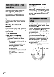
...to their factory settings. • All settings in the display. For the adjustable parameters, see the table on the power, clear the receiver's memory. Tip To check the audio output during settings (to set to the side, depending on the shape of input selectors and ...the speaker parameters (size, position, etc.) and perform any other settings. Performing initial setup operations Once you . Clearing the receiver's memory Before using your receiver for your system. The front speakers can place the surround speakers either behind you have hooked up the speakers and turned ...
...to their factory settings. • All settings in the display. For the adjustable parameters, see the table on the power, clear the receiver's memory. Tip To check the audio output during settings (to set to the side, depending on the shape of input selectors and ...the speaker parameters (size, position, etc.) and perform any other settings. Performing initial setup operations Once you . Clearing the receiver's memory Before using your receiver for your system. The front speakers can place the surround speakers either behind you have hooked up the speakers and turned ...
Operating Instructions
Page 17
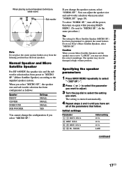
... you use Micro Satellite Speakers and the speaker size is entered automatically. 4 Repeat steps 2 and 3 until you have set to select the setting you use Sony's Micro Satellite Speakers, select "MICRO SP.". Initial settings Parameter L R DIST. Hooking Up and Setting Up the Speaker System When placing surround speakers behind you select...
... you use Micro Satellite Speakers and the speaker size is entered automatically. 4 Repeat steps 2 and 3 until you have set to select the setting you use Sony's Micro Satellite Speakers, select "MICRO SP.". Initial settings Parameter L R DIST. Hooking Up and Setting Up the Speaker System When placing surround speakers behind you select...
Operating Instructions
Page 18
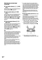
Tip The receiver allows you to enjoy surround sound. B B 60 A A 30 * These parameters are too close, setting the surround speaker distance closer (shorter) than the front speakers. XX ...
Tip The receiver allows you to enjoy surround sound. B B 60 A A 30 * These parameters are too close, setting the surround speaker distance closer (shorter) than the front speakers. XX ...
Operating Instructions
Page 19
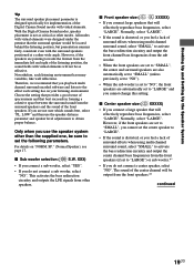
All modes with virtual elements were designed under the premise that will be located behind the listening position, but presentation remains fairly consistent even with the surround speakers positioned at a rather wide angle. Choose the setting that provides a good sense of spaciousness and that best succeeds in forming a cohesive space between the surround sound from the surround speakers and the sound of surround effects when using multi channel surround sound, select "SMALL" to activate the bass redirection circuitry and output the center channel bass frequencies from the front ...
All modes with virtual elements were designed under the premise that will be located behind the listening position, but presentation remains fairly consistent even with the surround speakers positioned at a rather wide angle. Choose the setting that provides a good sense of spaciousness and that best succeeds in forming a cohesive space between the surround sound from the surround speakers and the sound of surround effects when using multi channel surround sound, select "SMALL" to activate the bass redirection circuitry and output the center channel bass frequencies from the front ...