Operating Instructions
Page 2
... turning the equipment off and on a circuit different from that may cause undesired operation. Owner's Record The model and serial numbers are present inside the unit. Record these numbers in a particular installation. Do not open the cabinet. FCC Notice This equipment has been tested and found to which can radiate radio frequency energy and, if not installed and used in this manual...
... turning the equipment off and on a circuit different from that may cause undesired operation. Owner's Record The model and serial numbers are present inside the unit. Record these numbers in a particular installation. Do not open the cabinet. FCC Notice This equipment has been tested and found to which can radiate radio frequency energy and, if not installed and used in this manual...
Operating Instructions
Page 3
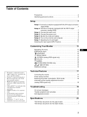
... with the DVI output connector (digital RGB 7 Setup 2: Connect a computer equipped with the HD15 output connector (analog RGB 7 Setup 3: Connect the audio cord 8 Setup 4: Connect the power cord 8 Setup 5: Bundle the cords and cables 9 Setup 6: Turn on the monitor and computer 9 Setup 7: Adjusting the tilt and height 10 Selecting the input signal (INPUT button 11 Customizing Your Monitor 12 Navigating the menu 12 US BACKLIGHT 12 CONTRAST 12 BRIGHTNESS 12 SCREEN (analog RGB signal only 13 COLOR 14 GAMMA 15 ZOOM (SDM-X72/X82 only 15 SMOOTHING 15 Additional settings 16 Technical...
... with the DVI output connector (digital RGB 7 Setup 2: Connect a computer equipped with the HD15 output connector (analog RGB 7 Setup 3: Connect the audio cord 8 Setup 4: Connect the power cord 8 Setup 5: Bundle the cords and cables 9 Setup 6: Turn on the monitor and computer 9 Setup 7: Adjusting the tilt and height 10 Selecting the input signal (INPUT button 11 Customizing Your Monitor 12 Navigating the menu 12 US BACKLIGHT 12 CONTRAST 12 BRIGHTNESS 12 SCREEN (analog RGB signal only 13 COLOR 14 GAMMA 15 ZOOM (SDM-X72/X82 only 15 SMOOTHING 15 Additional settings 16 Technical...
Operating Instructions
Page 4
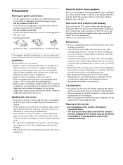
..., tapes, and floppy discs away from the speaker's opening as this monitor for repair or shipment, use any type of dust, dirt, or sand, for 240 V AC only The equipment should be sure to unplug the power cord from the monitor and grasp the support and base sections of the display stand firmly with your local sanitation authority. 4 Precautions Warning on the LCD screen.
..., tapes, and floppy discs away from the speaker's opening as this monitor for repair or shipment, use any type of dust, dirt, or sand, for 240 V AC only The equipment should be sure to unplug the power cord from the monitor and grasp the support and base sections of the display stand firmly with your local sanitation authority. 4 Precautions Warning on the LCD screen.
Operating Instructions
Page 5
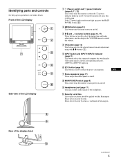
... 7 Stereo speakers (page 17) These output the audio signals as sound. 8 MAIN POWER switch (page 9) This switch turns the monitor's main power on and off , press this switch again. To turn the monitor off . 3 M/m and 2 (volume) buttons (page 12, 17) These buttons are used to select the menu items and make adjustments, and also display the VOLUME menu to reduce the power consumption. Rear of Kensington. Front of the LCD display Side view of the LCD display 1 1 (Power) switch and 1 (power) indicator...
... 7 Stereo speakers (page 17) These output the audio signals as sound. 8 MAIN POWER switch (page 9) This switch turns the monitor's main power on and off , press this switch again. To turn the monitor off . 3 M/m and 2 (volume) buttons (page 12, 17) These buttons are used to select the menu items and make adjustments, and also display the VOLUME menu to reduce the power consumption. Rear of Kensington. Front of the LCD display Side view of the LCD display 1 1 (Power) switch and 1 (power) indicator...
Operating Instructions
Page 6
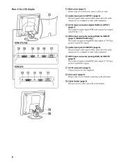
... connector (analog RGB) for INPUT2 (page 8) This connector inputs analog RGB video signals (0.700 Vp-p, positive) and SYNC signals. ql Cable holder (page 9) This part secures cables and cords to bundle connecting cords and cables. Rear of a computer or other audio equipment. qk Arm cover (page 9) Remove this cover when you connect cables or cords. qd DVI-D input connector (digital RGB) for INPUT2 (page 8) This jack inputs audio signals when connected to the audio output jack of the LCD display SDM-X72/X82 SDM-X52 qa Back cover (page 7) Remove this cover to the monitor...
... connector (analog RGB) for INPUT2 (page 8) This connector inputs analog RGB video signals (0.700 Vp-p, positive) and SYNC signals. ql Cable holder (page 9) This part secures cables and cords to bundle connecting cords and cables. Rear of a computer or other audio equipment. qk Arm cover (page 9) Remove this cover when you connect cables or cords. qd DVI-D input connector (digital RGB) for INPUT2 (page 8) This jack inputs audio signals when connected to the audio output jack of the LCD display SDM-X72/X82 SDM-X52 qa Back cover (page 7) Remove this cover to the monitor...
Operating Instructions
Page 7
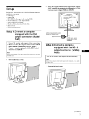
...analog US RGB) Turn off the monitor and computer before connecting. • When connecting the computer to the monitor's HD15 input connector (analog RGB), refer to the monitor's DVI-D input connector (digital RGB) for INPUT1. Setup Before using your monitor, check that the following items are included in your carton: • LCD display • Power cord • HD15-HD15 video signal cable (analog RGB) • DVI-D video signal cable (digital RGB) • Audio cord (stereo miniplug) • Windows Utility/Macintosh Utility Disk • Warranty card • This instruction manual...
...analog US RGB) Turn off the monitor and computer before connecting. • When connecting the computer to the monitor's HD15 input connector (analog RGB), refer to the monitor's DVI-D input connector (digital RGB) for INPUT1. Setup Before using your monitor, check that the following items are included in your carton: • LCD display • Power cord • HD15-HD15 video signal cable (analog RGB) • DVI-D video signal cable (digital RGB) • Audio cord (stereo miniplug) • Windows Utility/Macintosh Utility Disk • Warranty card • This instruction manual...
Operating Instructions
Page 8
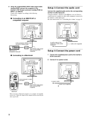
...compatible computer Setup 3:Connect the audio cord Connect the supplied audio cord to a power outlet. For more information, see "Controlling the volume" on page 17. 2 Using the supplied HD15-HD15 video signal cable (analog RGB), connect the computer to power outlet power cord (supplied) 2 8 to the monitor's HD 15 input connector (analog RGB) for INPUT1 or INPUT2 to audio output of the computer or other audio equipment connected to the computer's output connector HD15-HD15 video signal cable (analog RGB) (supplied) Macintosh When connecting a Macintosh computer, use an adapter...
...compatible computer Setup 3:Connect the audio cord Connect the supplied audio cord to a power outlet. For more information, see "Controlling the volume" on page 17. 2 Using the supplied HD15-HD15 video signal cable (analog RGB), connect the computer to power outlet power cord (supplied) 2 8 to the monitor's HD 15 input connector (analog RGB) for INPUT1 or INPUT2 to audio output of the computer or other audio equipment connected to the computer's output connector HD15-HD15 video signal cable (analog RGB) (supplied) Macintosh When connecting a Macintosh computer, use an adapter...
Operating Instructions
Page 9
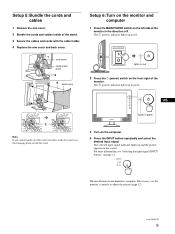
... [. The installation of the monitor. MAIN POWER lights in red. For more information, see "Selecting the input signal (INPUT button)" on the screen. US 3 Note If you cannot bundle all of the cords and cables inside of the stand. 3 Secure the cables and cords with the cable holder. 4 Replace the arm cover and back cover. 1 arm cover Hold at this point. 2 4 back cover Setup 6: Turn on the monitor and computer 1 Press the MAIN POWER switch on...
... [. The installation of the monitor. MAIN POWER lights in red. For more information, see "Selecting the input signal (INPUT button)" on the screen. US 3 Note If you cannot bundle all of the cords and cables inside of the stand. 3 Secure the cables and cords with the cable holder. 4 Replace the arm cover and back cover. 1 arm cover Hold at this point. 2 4 back cover Setup 6: Turn on the monitor and computer 1 Press the MAIN POWER switch on...
Operating Instructions
Page 10
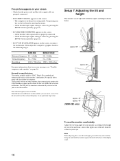
... the display stand. 10 The Plug & Play monitor is automatically selected so that you turn on your computer after connecting the monitor, the setup Wizard may appear on the screen, reconnect the old monitor. Since flickers are properly connected. • If NO INPUT SIGNAL appears on the screen: - Then adjust the computer's graphics board in the power saving mode. Check that the input signal setting is not reflected from the screen to the computer. No specific driver needs...
... the display stand. 10 The Plug & Play monitor is automatically selected so that you turn on your computer after connecting the monitor, the setup Wizard may appear on the screen, reconnect the old monitor. Since flickers are properly connected. • If NO INPUT SIGNAL appears on the screen: - Then adjust the computer's graphics board in the power saving mode. Check that the input signal setting is not reflected from the screen to the computer. No specific driver needs...
Operating Instructions
Page 12
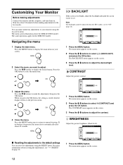
... your monitor using the RESET menu. Note The backlight cannot be adjusted when the ECO mode is too bright, adjust the backlight and make numerous adjustments to the previous menu. BRIGHTNESS Adjust the picture brightness (black level). The same operations apply for the SDM-X52 model. Press the M/m buttons to display the desired menu. If no buttons are pressed, the menu closes automatically after about resetting the adjustments, see . BACKLIGHT If the screen is set to see "0 (RESET)" on the screen. 2 Press the M/m buttons...
... your monitor using the RESET menu. Note The backlight cannot be adjusted when the ECO mode is too bright, adjust the backlight and make numerous adjustments to the previous menu. BRIGHTNESS Adjust the picture brightness (black level). The same operations apply for the SDM-X52 model. Press the M/m buttons to display the desired menu. If no buttons are pressed, the menu closes automatically after about resetting the adjustments, see . BACKLIGHT If the screen is set to see "0 (RESET)" on the screen. 2 Press the M/m buttons...
Operating Instructions
Page 13
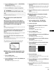
...) and position (horizontal/vertical position). SCREEN (analog RGB signal only) Note When receiving digital RGB signals from the DVI-D input connector for the current input signal. (See AUTO below.) If you still need to select (SCREEN) and press the OK button. These adjustments are observed over the entire screen, adjust pitch by the following steps. 9 Press the M/m buttons to make further automatic adjustment of the screen's phase, pitch and horizontal/vertical position for the current input signal (AUTO) 1 Press the MENU button. If vertical stripes are...
...) and position (horizontal/vertical position). SCREEN (analog RGB signal only) Note When receiving digital RGB signals from the DVI-D input connector for the current input signal. (See AUTO below.) If you still need to select (SCREEN) and press the OK button. These adjustments are observed over the entire screen, adjust pitch by the following steps. 9 Press the M/m buttons to make further automatic adjustment of the screen's phase, pitch and horizontal/vertical position for the current input signal (AUTO) 1 Press the MENU button. If vertical stripes are...
Operating Instructions
Page 14
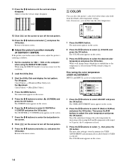
... the screen to select (COLOR) and press the OK button. When using the SDM-X72/X82 model. Since this adjustment changes the color temperature by increasing or decreasing the R and B components with respect to G (green), the G component is fixed. 3 Press the M/m buttons to the menu screen. The main menu appears on the computer when using the SDM-X52 model, it is lowered from the default color temperature settings. Adjust so that the vertical stripes...
... the screen to select (COLOR) and press the OK button. When using the SDM-X72/X82 model. Since this adjustment changes the color temperature by increasing or decreasing the R and B components with respect to G (green), the G component is fixed. 3 Press the M/m buttons to the menu screen. The main menu appears on the computer when using the SDM-X52 model, it is lowered from the default color temperature settings. Adjust so that the vertical stripes...
Operating Instructions
Page 15
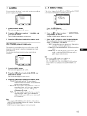
... default setting): Standard smoothing effect. • GRAPHICS: To make the pictures appear clean. (This US mode is suited for CD-ROM software such as photo images or illustrations.) Note • When you set to display the picture on the screen. 3 Press the M/m buttons to select the desired mode. GAMMA GAMMA 1 GAMMA 2 GAMMA 3 1280 x1024 / 60Hz EX I T 1 Press the MENU button. Note • When using the SDM-X72/X82 model...
... default setting): Standard smoothing effect. • GRAPHICS: To make the pictures appear clean. (This US mode is suited for CD-ROM software such as photo images or illustrations.) Note • When you set to display the picture on the screen. 3 Press the M/m buttons to select the desired mode. GAMMA GAMMA 1 GAMMA 2 GAMMA 3 1280 x1024 / 60Hz EX I T 1 Press the MENU button. Note • When using the SDM-X72/X82 model...
Operating Instructions
Page 16
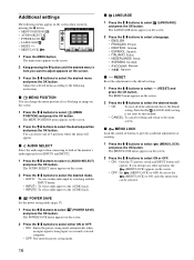
... the power saving mode. 16 x LANGUAGE 1 Press the M/m buttons to select (MENU POSITION) and press the OK button. x ZZ... Note that the (LANGUAGE) setting is being input via the AUDIO2 jack. x MENU POSITION You can be selected. Additional settings The following instructions. The LANGUAGE menu appears on the screen. 1 Press the M/m buttons to select (LANGUAGE) and press the OK button. If you keep pressing the m button. • MENU POSITION MENU POS I T I ON • AUDIO SELECT ZZ... • POWER SAVE...
... the power saving mode. 16 x LANGUAGE 1 Press the M/m buttons to select (MENU POSITION) and press the OK button. x ZZ... Note that the (LANGUAGE) setting is being input via the AUDIO2 jack. x MENU POSITION You can be selected. Additional settings The following instructions. The LANGUAGE menu appears on the screen. 1 Press the M/m buttons to select (LANGUAGE) and press the OK button. If you keep pressing the m button. • MENU POSITION MENU POS I T I ON • AUDIO SELECT ZZ... • POWER SAVE...
Operating Instructions
Page 17
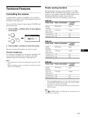
..." mode, the input signal is cut and NO INPUT SIGNAL appears on the screen. • When your monitor is in power saving mode, no menu appears on the screen. Note If the ZZ... (POWER SAVE) is connected to the monitor's audio input jacks. VOLUME , 30 2 Press the M/m (2) buttons to OFF (page 16), the monitor does not enter the power saving mode. 17 If the monitor is set by VESA, ENERGY STAR, and NUTEK. Technical Features Controlling the volume Using the monitor's speakers...
..." mode, the input signal is cut and NO INPUT SIGNAL appears on the screen. • When your monitor is in power saving mode, no menu appears on the screen. Note If the ZZ... (POWER SAVE) is connected to the monitor's audio input jacks. VOLUME , 30 2 Press the M/m (2) buttons to OFF (page 16), the monitor does not enter the power saving mode. 17 If the monitor is set by VESA, ENERGY STAR, and NUTEK. Technical Features Controlling the volume Using the monitor's speakers...
Operating Instructions
Page 18
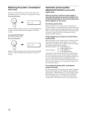
... monitor frequency ranges): Horizontal frequency: 28 - 61 kHz (SDM-X52) 28 - 92 kHz (SDM-X72/X82) Vertical frequency: 56 - 75 Hz (SDM-X52) 56 - 85 Hz (SDM-X72/X82) Consequently, the first time the monitor receives input signals that a clear picture appears on the front of the screen. Press the ECO button , ECO : ON The ECO: ON menu appears on the screen. The factory preset mode When the monitor receives an input signal, it automatically adjusts the picture's position...
... monitor frequency ranges): Horizontal frequency: 28 - 61 kHz (SDM-X52) 28 - 92 kHz (SDM-X72/X82) Vertical frequency: 56 - 75 Hz (SDM-X52) 56 - 85 Hz (SDM-X72/X82) Consequently, the first time the monitor receives input signals that a clear picture appears on the front of the screen. Press the ECO button , ECO : ON The ECO: ON menu appears on the screen. The factory preset mode When the monitor receives an input signal, it automatically adjusts the picture's position...
Operating Instructions
Page 19
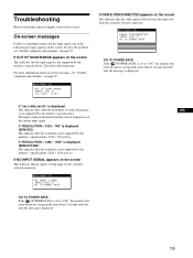
... displayed (SDM-X52) This indicates that the video signal cable has been disconnected from the time the message is not supported by the monitor's specifications (1024 × 768 or less). I NFORMA T I ON NO I NPUT S I GNA L I NPUT 1 : DV I - If NO INPUT SIGNAL appears on the screen This indicates that the resolution is being input via the currently selected connector. D GO TO POWER SAVE GO TO POWER SAVE If the ZZ... (POWER SAVE...
... displayed (SDM-X52) This indicates that the video signal cable has been disconnected from the time the message is not supported by the monitor's specifications (1024 × 768 or less). I NFORMA T I ON NO I NPUT S I GNA L I NPUT 1 : DV I - If NO INPUT SIGNAL appears on the screen This indicates that the resolution is being input via the currently selected connector. D GO TO POWER SAVE GO TO POWER SAVE If the ZZ... (POWER SAVE...
Operating Instructions
Page 20
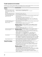
... problem. The 1 (power) indicator turns on red. • Check that is within that the graphics mode (VESA, Macintosh 19'' Color, etc.) and the frequency of the input signal are supported by the monitor • Check your graphics board is attached to the computer before entering the power saving mode. If CABLE DISCONNECTED appears on the screen before connecting the video signal cable. If NO INPUT SIGNAL appears on ." Connect the adapter to the computer properly. • Check that the monitor...
... problem. The 1 (power) indicator turns on red. • Check that is within that the graphics mode (VESA, Macintosh 19'' Color, etc.) and the frequency of the input signal are supported by the monitor • Check your graphics board is attached to the computer before entering the power saving mode. If CABLE DISCONNECTED appears on the screen before connecting the video signal cable. If NO INPUT SIGNAL appears on ." Connect the adapter to the computer properly. • Check that the monitor...
Operating Instructions
Page 21
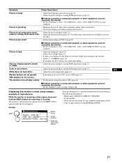
... of input signals (analog RGB/digital RGB) 21 Picture is visible. Picture is receiving a video signal, press and hold the MENU button for the display to become bright after a while. • Set the power saving function to OFF (page 16). US White does not look white. • Adjust the color temperature (page 14). Press the MENU button again to 1024 × 768 (SDM-X52), 1280 × 1024 (SDM-X72/X82) on the screen). • If the menu lock is...
... of input signals (analog RGB/digital RGB) 21 Picture is visible. Picture is receiving a video signal, press and hold the MENU button for the display to become bright after a while. • Set the power saving function to OFF (page 16). US White does not look white. • Adjust the color temperature (page 14). Press the MENU button again to 1024 × 768 (SDM-X52), 1280 × 1024 (SDM-X72/X82) on the screen). • If the menu lock is...
Operating Instructions
Page 22
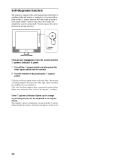
... is green 1 Turn off the 1 (power) switch and disconnect the video signal cables from the monitor. 2 Turn the monitor on by pressing the 1 (power) switch. If all four color bars appear (white, red, green, blue), the monitor is a potential monitor failure. If the 1 (power) indicator lights up in orange Try pressing any key on the keyboard or moving the mouse. Reconnect the video input cables and check the condition of the monitor's condition. The computer's power saving mode is a problem...
... is green 1 Turn off the 1 (power) switch and disconnect the video signal cables from the monitor. 2 Turn the monitor on by pressing the 1 (power) switch. If all four color bars appear (white, red, green, blue), the monitor is a potential monitor failure. If the 1 (power) indicator lights up in orange Try pressing any key on the keyboard or moving the mouse. Reconnect the video input cables and check the condition of the monitor's condition. The computer's power saving mode is a problem...


