
Operating Instructions
Page 6
... projector. Do not use a soft dry cloth. Never pull the cord itself has been turned off the power with the I / 1 key, do not disconnect the unit from the wall outlet if it is not to be exposed to direct lighting or sunlight. • Ceiling-mounted spot lighting is a normal result of light-reflecting material. On cleaning • To keep the cabinet looking new, periodically clean...
... projector. Do not use a soft dry cloth. Never pull the cord itself has been turned off the power with the I / 1 key, do not disconnect the unit from the wall outlet if it is not to be exposed to direct lighting or sunlight. • Ceiling-mounted spot lighting is a normal result of light-reflecting material. On cleaning • To keep the cabinet looking new, periodically clean...
Operating Instructions
Page 8
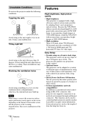
..., XGA panels provide a resolution of time the lamp has been on a slope of the projector. Blocking the ventilation holes Avoid using one of a breaker or other than 20 degrees. Because the VPL-PX40 utilizes a newly developed high N.A. LCD panel with a microlens and a 265W UHP lamp, it possible to control multiple projectors and also makes it can be set up . This is equipped with a long focus. • Direct Power...
..., XGA panels provide a resolution of time the lamp has been on a slope of the projector. Blocking the ventilation holes Avoid using one of a breaker or other than 20 degrees. Because the VPL-PX40 utilizes a newly developed high N.A. LCD panel with a microlens and a 265W UHP lamp, it possible to control multiple projectors and also makes it can be set up . This is equipped with a long focus. • Direct Power...
Operating Instructions
Page 10
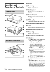
... (exhaust) i Focus ring Adjusts the picture focus. f Front remote control detector g Lens Remove the lens cap before projection. Flashes when the lamp cover or air filter cover is not secured firmly. • TEMP (Temperature)/FAN: Lights up or flashes under the following conditions: - Flashes when the fan is input for 10 minutes. For details on the LAMP/COVER and the TEMP/FAN indicators, see "Connector Panel" on page 13. j Rear remote control detector k Indicators • LAMP/COVER: Lights up when the projector is in the SET SETTING menu is set to...
... (exhaust) i Focus ring Adjusts the picture focus. f Front remote control detector g Lens Remove the lens cap before projection. Flashes when the lamp cover or air filter cover is not secured firmly. • TEMP (Temperature)/FAN: Lights up or flashes under the following conditions: - Flashes when the fan is input for 10 minutes. For details on the LAMP/COVER and the TEMP/FAN indicators, see "Connector Panel" on page 13. j Rear remote control detector k Indicators • LAMP/COVER: Lights up when the projector is in the SET SETTING menu is set to...

Operating Instructions
Page 11
.... to lower the projector to raise the projector Notes • Be careful not to use the adjuster To adjust the height Adjusts the height of Controls 11 GB Overview For fine adjustment, turn on . - Lights in red when a AC power cord is turned on the projector with the I / 1 key. Adjuster adjustment buttons 2 While pressing the buttons, adjust the projector to an optional security cable (Kensington's). o Adjuster p Speaker q Ventilation holes (intake)/air filter cover • Do not...
.... to lower the projector to raise the projector Notes • Be careful not to use the adjuster To adjust the height Adjusts the height of Controls 11 GB Overview For fine adjustment, turn on . - Lights in red when a AC power cord is turned on the projector with the I / 1 key. Adjuster adjustment buttons 2 While pressing the buttons, adjust the projector to an optional security cable (Kensington's). o Adjuster p Speaker q Ventilation holes (intake)/air filter cover • Do not...
Operating Instructions
Page 12
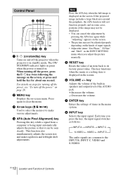
When turning off the power, press the I / 1 (on/standby) key Turns on the screen, or press and hold the key for turning off the power, see "To turn off the power" on . Control Panel MENU APA I/ ENTER RESET INPUT VOLUME CONT ETH INPU INPU a I / 1 key twice following the message on and off the projector when the projector is turned on page 28. The ON/ STANDBY indicator lights in green when the power is in standby mode. Press again to clear the menu. c Arrow keys (M/m/ For details on steps for about one second. b MENU key Displays the on-screen menu.
When turning off the power, press the I / 1 (on/standby) key Turns on the screen, or press and hold the key for turning off the power, see "To turn off the power" on . Control Panel MENU APA I/ ENTER RESET INPUT VOLUME CONT ETH INPU INPU a I / 1 key twice following the message on and off the projector when the projector is turned on page 28. The ON/ STANDBY indicator lights in green when the power is in standby mode. Press again to clear the menu. c Arrow keys (M/m/ For details on steps for about one second. b MENU key Displays the on-screen menu.

Operating Instructions
Page 15
Use the arrow keys (M/m/ Overview d D KEYSTONE key Corrects the trapezoidal distortion caused by the projection angle.
Use the arrow keys (M/m/ Overview d D KEYSTONE key Corrects the trapezoidal distortion caused by the projection angle.

Operating Instructions
Page 24
...the INPUT A connector INPUT A Computer connected to the INPUT B connector INPUT B Computer connected to the INPUT C (digital) connector INPUT C Computer connected to the INPUT D connector INPUT D Video equipment connected to select the input source. The ON/STANDBY indicator lights in green. 3 Turn on the equipment connected to the projector. 4 Press the INPUT key to the VIDEO input connector VIDEO GB 24 Projecting Projecting COMMAND OFF ON PIC PJ NETWORK MUTING AUDIO INPUT LENS APA D KEYSTONE VOLUME HELP MENU/ TAB LASER FREEZE Rear remote control detector MENU APA...
...the INPUT A connector INPUT A Computer connected to the INPUT B connector INPUT B Computer connected to the INPUT C (digital) connector INPUT C Computer connected to the INPUT D connector INPUT D Video equipment connected to select the input source. The ON/STANDBY indicator lights in green. 3 Turn on the equipment connected to the projector. 4 Press the INPUT key to the VIDEO input connector VIDEO GB 24 Projecting Projecting COMMAND OFF ON PIC PJ NETWORK MUTING AUDIO INPUT LENS APA D KEYSTONE VOLUME HELP MENU/ TAB LASER FREEZE Rear remote control detector MENU APA...
Operating Instructions
Page 27
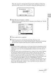
... used. Enter the password that using the security lock can prevent valid usage in such cases. INSTALL SETTING X Input A V Keystone: 0 Image Flip: Off Background: Blue Lamp Mode: Standard Direct Power On: Off High Altitude Mode:Off Security Lock: Off Invalid Password! 4 The security lock is completed. 5 Turn the main power off the power. • The security lock will not be set and the main power is turned off, the screen for entering the password is displayed when the power is turned...
... used. Enter the password that using the security lock can prevent valid usage in such cases. INSTALL SETTING X Input A V Keystone: 0 Image Flip: Off Background: Blue Lamp Mode: Standard Direct Power On: Off High Altitude Mode:Off Security Lock: Off Invalid Password! 4 The security lock is completed. 5 Turn the main power off the power. • The security lock will not be set and the main power is turned off, the screen for entering the password is displayed when the power is turned...

Operating Instructions
Page 28
..., clean the air filter every 1500 hours. appears to light up the ON/STANDBY indicator with the I / 1 key for a certain time even after the fan stops running and the ON/STANDBY indicator lights in a certain condition, you can turn off the power. During this time, you will cause the fan to turn off , set the direct power on -screen message in red. The internal circuitry will not be using a circuit breaker to automatically operate...
..., clean the air filter every 1500 hours. appears to light up the ON/STANDBY indicator with the I / 1 key for a certain time even after the fan stops running and the ON/STANDBY indicator lights in a certain condition, you can turn off the power. During this time, you will cause the fan to turn off , set the direct power on -screen message in red. The internal circuitry will not be using a circuit breaker to automatically operate...

Operating Instructions
Page 30
...Mode: Color Temp: Standard 80 50 30 Graphics High Input A GB 30 Using the MENU x is displayed when no signal is shown as a yellow button. The setting items are displayed in a pop-up menu Selected input Menu Setting items signal MENU SETTING Status: Language: Menu Position: Menu Color: Input A Input signal setting indicator For Input D: Shows "Computer", "Component" or "Video GBR". Display items Input signal indicator Video NTSC 4.43 Input signal setting indicator Picture adjustment menu Contrast Input signal indicator Shows the selected input channel. You can change the menu...
...Mode: Color Temp: Standard 80 50 30 Graphics High Input A GB 30 Using the MENU x is displayed when no signal is shown as a yellow button. The setting items are displayed in a pop-up menu Selected input Menu Setting items signal MENU SETTING Status: Language: Menu Position: Menu Color: Input A Input signal setting indicator For Input D: Shows "Computer", "Component" or "Video GBR". Display items Input signal indicator Video NTSC 4.43 Input signal setting indicator Picture adjustment menu Contrast Input signal indicator Shows the selected input channel. You can change the menu...
Operating Instructions
Page 34
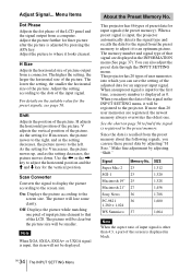
... the signal to display the picture according to the screen size. The picture will not be displayed. This projector has 46 types of the LCD panel and the signal output from a connector. The memory number and signal type of that of user memories into which you can also adjust the preset data through the INPUT SETTING menu. This projector has 20 types of the LCD. Signal Super Mac-2 SGI-1 Macintosh 19" Macintosh 21" Sony...
... the signal to display the picture according to the screen size. The picture will not be displayed. This projector has 46 types of the LCD panel and the signal output from a connector. The memory number and signal type of that of user memories into which you can also adjust the preset data through the INPUT SETTING menu. This projector has 20 types of the LCD. Signal Super Mac-2 SGI-1 Macintosh 19" Macintosh 21" Sony...

Operating Instructions
Page 35
... of the input signal automatically. The SET SETTING Menu The SET SETTING menu is used for 10 minutes with no signal input. Input-D Signal Sel. IR Receiver Selects the remote control detectors (IR receiver) on the Remote Commander even if the Smart APA set to "On," the projector goes into power saving mode if you turn on the Remote Commander. 1) The APA (Auto Pixel Alignment) automatically adjusts "Dot Phase," "H Size" and "Shift" in the following sequence: Input-A/ Input-B/Input-C/Input-D/Video/S-Video. Rear: Activates...
... of the input signal automatically. The SET SETTING Menu The SET SETTING menu is used for 10 minutes with no signal input. Input-D Signal Sel. IR Receiver Selects the remote control detectors (IR receiver) on the Remote Commander even if the Smart APA set to "On," the projector goes into power saving mode if you turn on the Remote Commander. 1) The APA (Auto Pixel Alignment) automatically adjusts "Dot Phase," "H Size" and "Shift" in the following sequence: Input-A/ Input-B/Input-C/Input-D/Video/S-Video. Rear: Activates...

Operating Instructions
Page 36
...INSTALL SETTING V Keystone: 0 Image Flip: Off Background: Blue Lamp Mode: Standard Direct Power On: Off High Altitude Mode:Off Security Lock: Off Input A Menu Items Status (on-screen display) Sets up the on -screen displays. Menu Items V Keystone Corrects the trapezoid caused by the projection angle. GB 36 The MENU SETTING Menu Select Black or Blue. HV: Flips the image horizontally and vertically. MENU SETTING Status: Language: Menu Position: Menu Color: On English Center White Input A A The INSTALL SETTING Menu The INSTALL SETTING menu is used in the menu...
...INSTALL SETTING V Keystone: 0 Image Flip: Off Background: Blue Lamp Mode: Standard Direct Power On: Off High Altitude Mode:Off Security Lock: Off Input A Menu Items Status (on-screen display) Sets up the on -screen displays. Menu Items V Keystone Corrects the trapezoid caused by the projection angle. GB 36 The MENU SETTING Menu Select Black or Blue. HV: Flips the image horizontally and vertically. MENU SETTING Status: Language: Menu Position: Menu Color: On English Center White Input A A The INSTALL SETTING Menu The INSTALL SETTING menu is used in the menu...

Operating Instructions
Page 37
... Adress Displays the IP address that is set . You cannot alter the display. The INFORMATION Menu 37 GB Adjustments and Settings Using the Menu The displayed value is approximate. The brightness of the input signal. On: Turns on the screen. Standard:Reduces fan noise and power consumption. Lamp Mode Sets the lamp brightness in the projection. Note These only display on the security lock function, which locks the projector once a password has been set for the projector. Direct Power...
... Adress Displays the IP address that is set . You cannot alter the display. The INFORMATION Menu 37 GB Adjustments and Settings Using the Menu The displayed value is approximate. The brightness of the input signal. On: Turns on the screen. Standard:Reduces fan noise and power consumption. Lamp Mode Sets the lamp brightness in the projection. Note These only display on the security lock function, which locks the projector once a password has been set for the projector. Direct Power...
Operating Instructions
Page 38
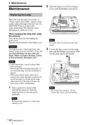
... The lamp becomes a high temperature after turning off the projector, then unplug the power cord. If you touch the lamp, you may scatter, causing injury. 1 Place a protective sheet (cloth) beneath the projector. Note For safety sake, do not loosen any other screws. 3 Loosen the three screws on the screen, replace the lamp with the Phillips screwdriver. GB 38 Maintenance appears on the lamp unit with a new...
... The lamp becomes a high temperature after turning off the projector, then unplug the power cord. If you touch the lamp, you may scatter, causing injury. 1 Place a protective sheet (cloth) beneath the projector. Note For safety sake, do not loosen any other screws. 3 Loosen the three screws on the screen, replace the lamp with the Phillips screwdriver. GB 38 Maintenance appears on the lamp unit with a new...

Operating Instructions
Page 39
.... 7 Connect the power cord and turn the projector to touch the glass surface of the lamp. • The power will not turn on the control panel in the following sequence for less than five seconds each: RESET, Notes • Be careful not to standby mode. 8 Press the following keys on if the lamp is securely in place. Note • Do not tighten the screws too...
.... 7 Connect the power cord and turn the projector to touch the glass surface of the lamp. • The power will not turn on the control panel in the following sequence for less than five seconds each: RESET, Notes • Be careful not to standby mode. 8 Press the following keys on if the lamp is securely in place. Note • Do not tighten the screws too...

Operating Instructions
Page 41
... before turning on the LCD panel. c Wait for Input-D Signal Sel. The picture from INPUT D connector is not turned on. • The power has been turned off and on the connected computer. and TEMP/FAN indicators c Consult with qualified Sony personnel. Picture Symptom Cause and Remedy No picture. • Cable is muting. in the SET SETTING menu is incorrect. c Select Computer, Video GBR or Component for Input-D Signal Sel. Troubleshooting 41 GB c Close the lamp cover securely...
... before turning on the LCD panel. c Wait for Input-D Signal Sel. The picture from INPUT D connector is not turned on. • The power has been turned off and on the connected computer. and TEMP/FAN indicators c Consult with qualified Sony personnel. Picture Symptom Cause and Remedy No picture. • Cable is muting. in the SET SETTING menu is incorrect. c Select Computer, Video GBR or Component for Input-D Signal Sel. Troubleshooting 41 GB c Close the lamp cover securely...

Operating Instructions
Page 43
...). The TEMP/FAN indicator • The fan is out of the acceptable range of the messages displayed on the screen. Both the LAMP/COVER • The electrical system breaks down the lamp and turn on the Remote Commander is time to NETWORK. c Turn off in the SET SETTING menu is set to replace the lamp. in 1 min. • Internal temperature is detached. The menu display does not • The PJ/NETWORK select switch on the power again (see...
...). The TEMP/FAN indicator • The fan is out of the acceptable range of the messages displayed on the screen. Both the LAMP/COVER • The electrical system breaks down the lamp and turn on the Remote Commander is time to NETWORK. c Turn off in the SET SETTING menu is set to replace the lamp. in 1 min. • Internal temperature is detached. The menu display does not • The PJ/NETWORK select switch on the power again (see...
Operating Instructions
Page 47
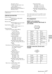
... of filters) Operating Instructions (1) Instalation Manual for replacement) (one pair of the items may not be available in some areas. Optional accessories Projector Lamp LMP-P260 (for replacement) Projector Suspension Support PSS-610 Monitor Cable SMF400 (HD D-sub 15-pin (male) y 5 × BNC (male)) Signal Interface Cable SIC10 (5 × BNC (male) y 5 × BNC (male)) Projection Lense Long focus zoom lens VPLL-ZM102 F = 2.0 to 2.6 f = 69 to 102 mm Manual focus/zoom Projection screen size 40...
... of filters) Operating Instructions (1) Instalation Manual for replacement) (one pair of the items may not be available in some areas. Optional accessories Projector Lamp LMP-P260 (for replacement) Projector Suspension Support PSS-610 Monitor Cable SMF400 (HD D-sub 15-pin (male) y 5 × BNC (male)) Signal Interface Cable SIC10 (5 × BNC (male) y 5 × BNC (male)) Projection Lense Long focus zoom lens VPLL-ZM102 F = 2.0 to 2.6 f = 69 to 102 mm Manual focus/zoom Projection screen size 40...

Operating Instructions
Page 53
... L Lamp Mode 37 Lamp replacement ..........38 Lamp Timer 37 Language 36 Location and function of controls connector panel ..........13 control panel 12 front/left side 10 rear/right side/bottom 10 M Menu clearing the menu display 31 INFORMATION menu 37 INPUT SETTING menu 33 INSTALL SETTING menu 36 MENU SETTING menu 36 PICTURE SETTING menu 31 SET SETTING menu .35 Menu Color 36 Menu Position 36 Message caution 44 warning 43 O Optional accessories .......47 OUTPUT connectors .....13 P Picture Mode 31 PICTURE SETTING Menu 31 Pin assignment 47 Power Turn on 24 Power Saving...
... L Lamp Mode 37 Lamp replacement ..........38 Lamp Timer 37 Language 36 Location and function of controls connector panel ..........13 control panel 12 front/left side 10 rear/right side/bottom 10 M Menu clearing the menu display 31 INFORMATION menu 37 INPUT SETTING menu 33 INSTALL SETTING menu 36 MENU SETTING menu 36 PICTURE SETTING menu 31 SET SETTING menu .35 Menu Color 36 Menu Position 36 Message caution 44 warning 43 O Optional accessories .......47 OUTPUT connectors .....13 P Picture Mode 31 PICTURE SETTING Menu 31 Pin assignment 47 Power Turn on 24 Power Saving...


