Operating Instructions
Page 2
... Parts and Controls ..... 7 Front Panel 7 Input Signals and Adjustable/Setting Items 11 Quad View Functions and Adjustable/ Setting Items 12 Rear Panel 13 Connecting the SDI Signals 14 Handling a USB memory stick 15 Notes on USB memory sticks 15 Removing the Stand (Included as Standard) ... 16 Attaching the Handle (For PVM-X1800 only) ... 16 Connecting the AC Power Cord 17 Selecting a Channel 17 Managing the Setting Values 18 About the Menu Screen 18 Using the Menu...
... Parts and Controls ..... 7 Front Panel 7 Input Signals and Adjustable/Setting Items 11 Quad View Functions and Adjustable/ Setting Items 12 Rear Panel 13 Connecting the SDI Signals 14 Handling a USB memory stick 15 Notes on USB memory sticks 15 Removing the Stand (Included as Standard) ... 16 Attaching the Handle (For PVM-X1800 only) ... 16 Connecting the AC Power Cord 17 Selecting a Channel 17 Managing the Setting Values 18 About the Menu Screen 18 Using the Menu...
Operating Instructions
Page 3
... display, such "stuck" pixels may be secured in consideration of the ventilation and service operation. Do not block the ventilation slots and vents of the fans. Leave a space around the unit for several days or more. Disconnect the power cord from the wall outlet if it can damage the screen. Connecting while turned on (red, green, or blue), or flashing...
... display, such "stuck" pixels may be secured in consideration of the ventilation and service operation. Do not block the ventilation slots and vents of the fans. Leave a space around the unit for several days or more. Disconnect the power cord from the wall outlet if it can damage the screen. Connecting while turned on (red, green, or blue), or flashing...
Operating Instructions
Page 4
... marker displays Press the MENU button to turn off the power when not in the "User Preset Setting" menu, HDR (High Dynamic Range) is not to turn off the power if the monitor is displayed. For details, refer to the operation manual of the connected equipment. Do not display static images that indicate settings or the operating state On-screen displays such as possible or reduce the input signal level...
... marker displays Press the MENU button to turn off the power when not in the "User Preset Setting" menu, HDR (High Dynamic Range) is not to turn off the power if the monitor is displayed. For details, refer to the operation manual of the connected equipment. Do not display static images that indicate settings or the operating state On-screen displays such as possible or reduce the input signal level...

Operating Instructions
Page 5
... Fan Error The unit has a built in fan for extended periods may result in red, turn off the power and contact an authorized Sony dealer. Make sure not to expose the unit to damage. Operating the unit while condensation is known as condensation. In addition, the screen is specially coated. 100% or more level without compressing the brightness parts...
... Fan Error The unit has a built in fan for extended periods may result in red, turn off the power and contact an authorized Sony dealer. Make sure not to expose the unit to damage. Operating the unit while condensation is known as condensation. In addition, the screen is specially coated. 100% or more level without compressing the brightness parts...

Operating Instructions
Page 7
.... Audio from the AUDIO output connector on /off the assigned function or switch the settings in this connector for loading 3D LUT files and future firmware updates. Audio is output from the speaker is not output when headphones are following: F1 button: Ch.1 F2 button: Ch.2 F3 button: Ch.3 F4 button: Ch.4 F5 button: Mono F6 button: Quad View F7 button: Blue Only F8 button: Internal Signal F9 button: Int. The factory default settings are connected...
.... Audio from the AUDIO output connector on /off the assigned function or switch the settings in this connector for loading 3D LUT files and future firmware updates. Audio is output from the speaker is not output when headphones are following: F1 button: Ch.1 F2 button: Ch.2 F3 button: Ch.3 F4 button: Ch.4 F5 button: Mono F6 button: Quad View F7 button: Blue Only F8 button: Internal Signal F9 button: Int. The factory default settings are connected...

Operating Instructions
Page 8
...," "Brightness," or "Contrast" for adjustment. When "Brightness" or "Contrast" is displayed on -screen menu. Also, the names of the F9 to F11 buttons to select the color R/G/B/RGB for the function button. Lights up in red during sleep mode and lights up in the "User Preset Setting" menu. The indicator displays the power status as follows. To change the settings, see "On High Brightness Display" (page 4). CAUTION indicator Flashes in the "User Preset Setting" menu F9 to F12 buttons Use to...
...," "Brightness," or "Contrast" for adjustment. When "Brightness" or "Contrast" is displayed on -screen menu. Also, the names of the F9 to F11 buttons to select the color R/G/B/RGB for the function button. Lights up in red during sleep mode and lights up in the "User Preset Setting" menu. The indicator displays the power status as follows. To change the settings, see "On High Brightness Display" (page 4). CAUTION indicator Flashes in the "User Preset Setting" menu F9 to F12 buttons Use to...

Operating Instructions
Page 9
...for the LCD panel activates. Setting" (page 21) in sleep mode. Adjusts the color intensity under "Ch. Button CONTRAST MANUAL button BRIGHT MANUAL button CHROMA MANUAL button PHASE MANUAL button Operations Not available on -screen menu is displayed, press the button to the previous value. Menu operation buttons Button MENU button ENTER button Operations When the on this unit. Button UP button DOWN button Operations When the menu is not displayed, press the button to confirm a menu item or setting value. Adjusts all the RGB (red/green/blue) together under "User Color Temp...
...for the LCD panel activates. Setting" (page 21) in sleep mode. Adjusts the color intensity under "Ch. Button CONTRAST MANUAL button BRIGHT MANUAL button CHROMA MANUAL button PHASE MANUAL button Operations Not available on -screen menu is displayed, press the button to the previous value. Menu operation buttons Button MENU button ENTER button Operations When the on this unit. Button UP button DOWN button Operations When the menu is not displayed, press the button to confirm a menu item or setting value. Adjusts all the RGB (red/green/blue) together under "User Color Temp...
Operating Instructions
Page 11
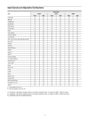
User Color Temp. (manual adjsutment) User LUT Marker Volume Audio Muting WFM 1) Vector 1) ALM 1) Internal Signal Int. Signal Pattern Pixel Zoom 2) Time Code Mono Blue Only R Off G Off B Off Native Scan Under Scan Black Detail Mode Dynamic Cont. Dr. Tally 3) : Adjustable/can be set × : Not adjustable/cannot be set 4K SDI YCbCr RGB × × ...
User Color Temp. (manual adjsutment) User LUT Marker Volume Audio Muting WFM 1) Vector 1) ALM 1) Internal Signal Int. Signal Pattern Pixel Zoom 2) Time Code Mono Blue Only R Off G Off B Off Native Scan Under Scan Black Detail Mode Dynamic Cont. Dr. Tally 3) : Adjustable/can be set × : Not adjustable/cannot be set 4K SDI YCbCr RGB × × ...
Operating Instructions
Page 12
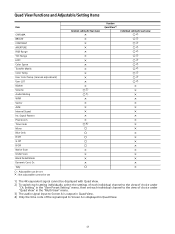
... View" menu. 3) The audio signal input to Screen A is output in Quad View. 12 Dr. Tally : Adjustable/can be set × : Not adjustable/cannot be set each individual channel to the view of choice under "Ch. Quad View Functions and Adjustable/Setting Items Item CHROMA BRIGHT CONTRAST APERTURE RGB Range YCC Range EOTF Color Space Transfer Matrix Color Temp. Signal Pattern Pixel Zoom Time Code Mono Blue Only R Off G Off B Off Native Scan Under Scan Black Detail Mode...
... View" menu. 3) The audio signal input to Screen A is output in Quad View. 12 Dr. Tally : Adjustable/can be set × : Not adjustable/cannot be set each individual channel to the view of choice under "Ch. Quad View Functions and Adjustable/Setting Items Item CHROMA BRIGHT CONTRAST APERTURE RGB Range YCC Range EOTF Color Space Transfer Matrix Color Temp. Signal Pattern Pixel Zoom Time Code Mono Blue Only R Off G Off B Off Native Scan Under Scan Black Detail Mode...
Operating Instructions
Page 13
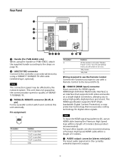
... input audio signal set under "Marker Preset" in the "User Preset Setting" menu are all turned on page 16. LAN (10/100) connector Connect to enjoy high quality digital picture and sound. To input other signals, we also recommend using a Premium High Speed HDMI cable within a length of 10BASET/100BASE-TX. PARALLEL REMOTE connector (RJ-45, 8pin) Forms a parallel control switch and controls this unit externally. Rear Panel Handle (For PVM-X2400...
... input audio signal set under "Marker Preset" in the "User Preset Setting" menu are all turned on page 16. LAN (10/100) connector Connect to enjoy high quality digital picture and sound. To input other signals, we also recommend using a Premium High Speed HDMI cable within a length of 10BASET/100BASE-TX. PARALLEL REMOTE connector (RJ-45, 8pin) Forms a parallel control switch and controls this unit externally. Rear Panel Handle (For PVM-X2400...

Operating Instructions
Page 14
... (SDI input) connectors (BNC) Input connectors for serial digital signals. To change the settings, see "Connecting the SDI Signals" (page 14). or an equivalent) is recommended. DC IN 22 to 32 V (DC power input) connector Connect to a DC 22 V to 32 V DC power supply. For details, see "Auto Power Down" (page 38) of Sub image 4 (lower-right screen) Connector 1 to 4 1, 3 1 2 3 4 1 2 3 4 1 2 3 4 Maximum 4 channels 2 channels 2 channels 1 channel 1 channel 14 To turn on the monitor, press...
... (SDI input) connectors (BNC) Input connectors for serial digital signals. To change the settings, see "Connecting the SDI Signals" (page 14). or an equivalent) is recommended. DC IN 22 to 32 V (DC power input) connector Connect to a DC 22 V to 32 V DC power supply. For details, see "Auto Power Down" (page 38) of Sub image 4 (lower-right screen) Connector 1 to 4 1, 3 1 2 3 4 1 2 3 4 1 2 3 4 Maximum 4 channels 2 channels 2 channels 1 channel 1 channel 14 To turn on the monitor, press...
Operating Instructions
Page 17
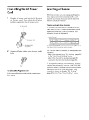
... AC plug holder while pressing the lock levers. When you can also switch channels by assigning a specific channel to display "Ch. Connecting the AC Power Cord 1 Plug the AC power cord into the AC IN socket on the above screen, then press the SELECT/ENTER control for each channel and easily view and switch channels with the CH SELECT button. You can assign settings like input signal and color temperature...
... AC plug holder while pressing the lock levers. When you can also switch channels by assigning a specific channel to display "Ch. Connecting the AC Power Cord 1 Plug the AC power cord into the AC IN socket on the above screen, then press the SELECT/ENTER control for each channel and easily view and switch channels with the CH SELECT button. You can assign settings like input signal and color temperature...
Operating Instructions
Page 18
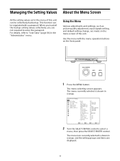
... orange. 2 Turn the SELECT/ENTER control to select a menu, then press the SELECT/ENTER control. This function can be regulated with the menu operation buttons on the menu screen of this unit can be collectively backed up. Managing the Setting Values About the Menu Screen All the setting values set in the menu of the unit. Using the Menu Various adjustments and settings, such as picture quality adjustment, input signals setting, and default setting change, are...
... orange. 2 Turn the SELECT/ENTER control to select a menu, then press the SELECT/ENTER control. This function can be regulated with the menu operation buttons on the menu screen of this unit can be collectively backed up. Managing the Setting Values About the Menu Screen All the setting values set in the menu of the unit. Using the Menu Various adjustments and settings, such as picture quality adjustment, input signals setting, and default setting change, are...
Operating Instructions
Page 23
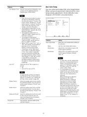
... (SDR) When R/G/B Bias is adjusted by fixing the backlight brightness. Select the audio preset to "2.2," "2.4," or "2.6," the contrast control method depends on the "Quad View Display" setting located under "Brightness" of "SMPTE ST 2084." When "EOTF" is adjusted with the PLUGE signal, etc. Submenu Setting Chr./Bright./Cont. Name R/G/B Gain R/G/B Bias Setting Select the color temperature setting to be adjusted. Adjusts the color balance (bias) of R (red)/G (green)/B (blue). Black levels fluctuate to select...
... (SDR) When R/G/B Bias is adjusted by fixing the backlight brightness. Select the audio preset to "2.2," "2.4," or "2.6," the contrast control method depends on the "Quad View Display" setting located under "Brightness" of "SMPTE ST 2084." When "EOTF" is adjusted with the PLUGE signal, etc. Submenu Setting Chr./Bright./Cont. Name R/G/B Gain R/G/B Bias Setting Select the color temperature setting to be adjusted. Adjusts the color balance (bias) of R (red)/G (green)/B (blue). Black levels fluctuate to select...

Operating Instructions
Page 27
... of the area marker 1/2. Submenu Setting V Position: Sets the vertical position of the marker at the top left corner of the image display area as the starting point when "Flexible Area" is selected in "Area Mode." You can set to a position from 1 to 2159. Width: Sets the width of the selected audio preset. Sets the audio channel when SDI signal is selected in "Area...
... of the area marker 1/2. Submenu Setting V Position: Sets the vertical position of the marker at the top left corner of the image display area as the starting point when "Flexible Area" is selected in "Area Mode." You can set to a position from 1 to 2159. Width: Sets the width of the selected audio preset. Sets the audio channel when SDI signal is selected in "Area...

Operating Instructions
Page 30
... are input. Sets the background of the specified signal level is colored in "WFM Setting," magenta does not appear on the waveform monitor. Off: Does not highlight large frequency areas. The displayed image is selected Level: Select the display level for Over Range. When "On" is hidden behind the WFM (Wave Form Monitor), Vector (vector scope), or the audio level meter screen. Sets...
... are input. Sets the background of the specified signal level is colored in "WFM Setting," magenta does not appear on the waveform monitor. Off: Does not highlight large frequency areas. The displayed image is selected Level: Select the display level for Over Range. When "On" is hidden behind the WFM (Wave Form Monitor), Vector (vector scope), or the audio level meter screen. Sets...

Operating Instructions
Page 31
... WFM (Wave Form Monitor) and Vector (vector scope). Off: Displays the normal waveform. Internal Signal Pixel Zoom Submenu Pixel Zoom Setting Sets whether to "On" automatically activates Native Scan. Submenu Internal Signal Pattern Setting Turns the internal signal display On/ Off. On: The internal signal is displayed. Off: The internal signal is not available. When using the pixel zoom, the center part of the line specified...
... WFM (Wave Form Monitor) and Vector (vector scope). Off: Displays the normal waveform. Internal Signal Pixel Zoom Submenu Pixel Zoom Setting Sets whether to "On" automatically activates Native Scan. Submenu Internal Signal Pattern Setting Turns the internal signal display On/ Off. On: The internal signal is displayed. Off: The internal signal is not available. When using the pixel zoom, the center part of the line specified...

Operating Instructions
Page 34
... image displayed directly from pixels (On). Aspect Marker-Line Press the button to display the internal signal. Blank.-Black" settings are not enlarged up to the end of the display. When "Native Scan" is set the aspect blanking to 9 on the controller Mono (black and white) Press the button to turn off the B (blue) signal. Internal Signal Press the button to display the line of the button, the picture switches to "Gray," "White," and "Color...
... image displayed directly from pixels (On). Aspect Marker-Line Press the button to display the internal signal. Blank.-Black" settings are not enlarged up to the end of the display. When "Native Scan" is set the aspect blanking to 9 on the controller Mono (black and white) Press the button to turn off the B (blue) signal. Internal Signal Press the button to display the line of the button, the picture switches to "Gray," "White," and "Color...

Operating Instructions
Page 38
... monitor is hidden. To cancel the settings, select "Off." (Default value: On) Note While the internal signal is displayed, Auto Power Down is "High" or "Low." Submenu Black Detail Mode Zebra Dynamic Cont. Dr. Setting Faithfully reproduces dark scenes with different levels of backlight brightness. Clipping occurs for about seven seconds when the input of the signal starts. Off: The display is automatically turned off. When set...
... monitor is hidden. To cancel the settings, select "Off." (Default value: On) Note While the internal signal is displayed, Auto Power Down is "High" or "Low." Submenu Black Detail Mode Zebra Dynamic Cont. Dr. Setting Faithfully reproduces dark scenes with different levels of backlight brightness. Clipping occurs for about seven seconds when the input of the signal starts. Off: The display is automatically turned off. When set...
Operating Instructions
Page 40
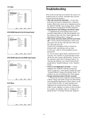
..., refer to Sony qualified service personnel. When the menu is assigned to function buttons. Adjustments and settings cannot be made Adjustments and settings may turn on the monitor for 60 minutes, the monitor is automatically turned off by the auto power-off . Display a white screen display or a video on the monitor, press the (Power) switch. Ch. Check if the ventilation slots or vents are displayed for the HDMI signal input) Unit Status Troubleshooting This section...
..., refer to Sony qualified service personnel. When the menu is assigned to function buttons. Adjustments and settings cannot be made Adjustments and settings may turn on the monitor for 60 minutes, the monitor is automatically turned off by the auto power-off . Display a white screen display or a video on the monitor, press the (Power) switch. Ch. Check if the ventilation slots or vents are displayed for the HDMI signal input) Unit Status Troubleshooting This section...


