Operating Instructions
Page 4
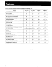
Horizontal/vertical delay mode Users control memory • - External sync input Color temperature selector Light-touch picture adjustment buttons EIA standard 19-inch rack mounting PVM-1344O PVM-1342Q ^ Yes Yes Yes Yes No No Yes Yes Yes No No • Yes No Yes Yes Yes Yes Yes Yes Yes Yes Yes PAL, SECAM, ...
Horizontal/vertical delay mode Users control memory • - External sync input Color temperature selector Light-touch picture adjustment buttons EIA standard 19-inch rack mounting PVM-1344O PVM-1342Q ^ Yes Yes Yes Yes No No Yes Yes Yes No No • Yes No Yes Yes Yes Yes Yes Yes Yes Yes Yes PAL, SECAM, ...
Operating Instructions
Page 5
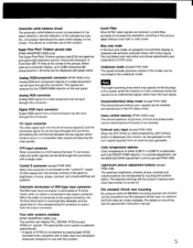
... SYNC)) button is obtained with all three cathodes driven with this connector. Super Fine Pitch Trinitron picutre tube (PVM-1344Q/PVM-1342Q only) The Super Fine Pitch Trinitron picture tube (0.25 mm aperture grill) gives high resolution picture. recorded video cassettes with a video tape recorder/player especially designed for the beam distortion, secular distortion of...
... SYNC)) button is obtained with all three cathodes driven with this connector. Super Fine Pitch Trinitron picutre tube (PVM-1344Q/PVM-1342Q only) The Super Fine Pitch Trinitron picture tube (0.25 mm aperture grill) gives high resolution picture. recorded video cassettes with a video tape recorder/player especially designed for the beam distortion, secular distortion of...
Operating Instructions
Page 7
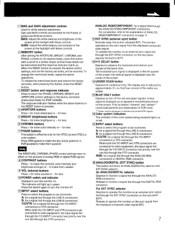
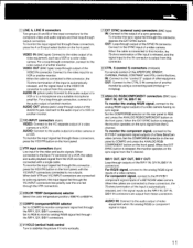
... Y/C-INPUT and VTR connectors are provided for a signal fed through the Y/C-INPUT connectors or VTR connector. The monitor operates on the pictures of ANALOG RGB/COMPONENT connectors on an external sync signal fed through the DIGITAL RGB connector. IllColor system indicators The indicator of the.../DIGITAL selector Depress to operate the monitor on the rear panel, depress the button (EXT). A blue signal is effective only for PVM-1444OM). for less. 7 PHASE buttons This button is displayed as ANALOG/DIGITAL selector andEXT SYNC selector. To release the memorized levels and...
... Y/C-INPUT and VTR connectors are provided for a signal fed through the Y/C-INPUT connectors or VTR connector. The monitor operates on the pictures of ANALOG RGB/COMPONENT connectors on an external sync signal fed through the DIGITAL RGB connector. IllColor system indicators The indicator of the.../DIGITAL selector Depress to operate the monitor on the rear panel, depress the button (EXT). A blue signal is effective only for PVM-1444OM). for less. 7 PHASE buttons This button is displayed as ANALOG/DIGITAL selector andEXT SYNC selector. To release the memorized levels and...
Operating Instructions
Page 8
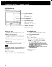
...through the VTR connector. for less. 1251POWER switch and indicator Same as M. Note The APERTURE, CHROMA, PHASE control settings have no effect on the pictures input through the LINE A connectors. for less. (201BRIGHT (brightness) control Turn toward + for more sharpness or toward - A: for a signal...toward GRN (green) to make the skin tones greenish or toward PUR (purple) to be monitored. Location and Function of Parts and Controls Front panel PVM-134O U U fi) 0 0 0 2 19 APERTURE control 20 BRIGHT (brightness) control 21 CHROMA control 0 PHASE control 231 CONTRAST control 1241 ...
...through the VTR connector. for less. 1251POWER switch and indicator Same as M. Note The APERTURE, CHROMA, PHASE control settings have no effect on the pictures input through the LINE A connectors. for less. (201BRIGHT (brightness) control Turn toward + for more sharpness or toward - A: for a signal...toward GRN (green) to make the skin tones greenish or toward PUR (purple) to be monitored. Location and Function of Parts and Controls Front panel PVM-134O U U fi) 0 0 0 2 19 APERTURE control 20 BRIGHT (brightness) control 21 CHROMA control 0 PHASE control 231 CONTRAST control 1241 ...
Operating Instructions
Page 9
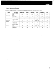
Model PVM-1344Q PVM-1342Q/ PVM-1341 PVM-1340 Input mode • LINE A, LINE B • Y/C • VTR Analog RGB Component • LINE A, LINE B • Y/C • VTR • Digital RGB • Analog RGB • ... Yes No Yes Yes Yes (NTSC only) No Yes Yes Yes Yes (NTSC only) No No Yes VOL Yes Yes Yes Yes No Yes No 9 Picture Adjustment Buttons The picture adjustment buttons of each monitor operate in the following input mode (indicated as "Yes").
Model PVM-1344Q PVM-1342Q/ PVM-1341 PVM-1340 Input mode • LINE A, LINE B • Y/C • VTR Analog RGB Component • LINE A, LINE B • Y/C • VTR • Digital RGB • Analog RGB • ... Yes No Yes Yes Yes (NTSC only) No Yes Yes Yes Yes (NTSC only) No No Yes VOL Yes Yes Yes Yes No Yes No 9 Picture Adjustment Buttons The picture adjustment buttons of each monitor operate in the following input mode (indicated as "Yes").
Operating Instructions
Page 11
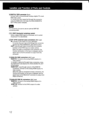
...monitor the input signal fed through the R/R-Y, G/Y, B/B-Y connectors. 6 V HOLD (vertical hold) control Turn to the analog RIG/B signal outputs of a Sony BetaCam video camera. Set to RGB to monitor analog R/G/B signal fed through these connectors, press the A or B input select button on the rear panel...9 ANALOG RGB/COMPONENT connectors (BNC type) Ft/R-Y IN, G/Y IN, B/B-Y IN: To monitor the analog R/G/B signal, connect to stabilize the picture if it rolls vertically. When the cable is input. 11 To monitor the component signal, connect to the IN connector is released, the monitor ...
...monitor the input signal fed through the R/R-Y, G/Y, B/B-Y connectors. 6 V HOLD (vertical hold) control Turn to the analog RIG/B signal outputs of a Sony BetaCam video camera. Set to RGB to monitor analog R/G/B signal fed through these connectors, press the A or B input select button on the rear panel...9 ANALOG RGB/COMPONENT connectors (BNC type) Ft/R-Y IN, G/Y IN, B/B-Y IN: To monitor the analog R/G/B signal, connect to stabilize the picture if it rolls vertically. When the cable is input. 11 To monitor the component signal, connect to the IN connector is released, the monitor ...
Operating Instructions
Page 12
... connection, be sure to use an optional SMF-520 connecting cable. 11 H CENT (horizontal centering) control When a digital R/G/B signal is monitored, turn to center the picture if it is output from this connector, the 75-ohms termination of a video camera. When the cable is connected to this connector. 13 ANALOG RGB...
... connection, be sure to use an optional SMF-520 connecting cable. 11 H CENT (horizontal centering) control When a digital R/G/B signal is monitored, turn to center the picture if it is output from this connector, the 75-ohms termination of a video camera. When the cable is connected to this connector. 13 ANALOG RGB...
Operating Instructions
Page 13
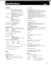
...(Typical) Peripheral area: 0.8 mm (Typical) Raster size stability H: 1.0%, V: 1.5% High voltage regulation Audio output 0.6 W (Max.) CRT PVM-1344Q/PVM-1342Q: SMPTE-C (American-standard-phosphor) PVM-1341/PVM-1340: P-22 Chromacity coordinates (SMPTE C only) X Y Red Green Blue 0.630 0.310 0.155 0.340 0.595 0.070 _ (tolerance...(at 4.5 MHz) Synchronization AFC time constant: 1 msec Line pull range Horizontal: ±500 Hz Vertical: 8 Hz Picture performance Normal scan 7°/8 overscan of CRT effective screen area Under scan 3% underscan of 75-percent chrominance) When the ...
...(Typical) Peripheral area: 0.8 mm (Typical) Raster size stability H: 1.0%, V: 1.5% High voltage regulation Audio output 0.6 W (Max.) CRT PVM-1344Q/PVM-1342Q: SMPTE-C (American-standard-phosphor) PVM-1341/PVM-1340: P-22 Chromacity coordinates (SMPTE C only) X Y Red Green Blue 0.630 0.310 0.155 0.340 0.595 0.070 _ (tolerance...(at 4.5 MHz) Synchronization AFC time constant: 1 msec Line pull range Horizontal: ±500 Hz Vertical: 8 Hz Picture performance Normal scan 7°/8 overscan of CRT effective screen area Under scan 3% underscan of 75-percent chrominance) When the ...


