System Reference Manual
Page 11
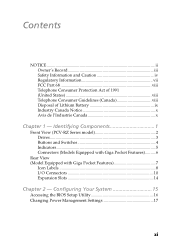
... (United States viii Telephone Consumer Guidelines (Canada viii Disposal of Lithium Battery ix Industry Canada Notice x Avis de l'Industrie Canada x Chapter 1 - Identifying Components 1 Front View (PCV-RZ Series model 2 Drives ...3 Buttons and Switches 4 Indicators 5 Connectors (Models Equipped with Giga Pocket Features)..........6 Rear View (Model Equipped with Giga Pocket Features 7 Icon Labels...
... (United States viii Telephone Consumer Guidelines (Canada viii Disposal of Lithium Battery ix Industry Canada Notice x Avis de l'Industrie Canada x Chapter 1 - Identifying Components 1 Front View (PCV-RZ Series model 2 Drives ...3 Buttons and Switches 4 Indicators 5 Connectors (Models Equipped with Giga Pocket Features)..........6 Rear View (Model Equipped with Giga Pocket Features 7 Icon Labels...
System Reference Manual
Page 13
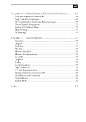
... 70 DMA Channel Assignments 72 System I /O and Expansion Slots 80 Floppy Disk Drive and Controller 80 Hard Drives and Controller 80 Optical Drives 81 System BIOS 81 Index 83 Specifications 77 Processor ...77 Chipset ...77 AGP Bus...77 PCI Bus ...78 Memory Modules 78 Memory Configurations 78 L2 Cache ...78 Graphics...
... 70 DMA Channel Assignments 72 System I /O and Expansion Slots 80 Floppy Disk Drive and Controller 80 Hard Drives and Controller 80 Optical Drives 81 System BIOS 81 Index 83 Specifications 77 Processor ...77 Chipset ...77 AGP Bus...77 PCI Bus ...78 Memory Modules 78 Memory Configurations 78 L2 Cache ...78 Graphics...
System Reference Manual
Page 29
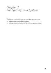
Chapter 2 Configuring Your System This chapter contains information on configuring your system. ❑ Making changes to the BIOS settings. ❑ Making changes to the display's power management settings. 15
Chapter 2 Configuring Your System This chapter contains information on configuring your system. ❑ Making changes to the BIOS settings. ❑ Making changes to the display's power management settings. 15
System Reference Manual
Page 30
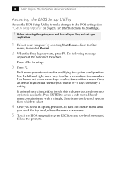
.... 4 Once you select an option, press ESC to select a menu from the Start menu, then select Restart. 2 When the Sony logo appears, press F3. Press for modifying the system configuration. Once an item is highlighted, use the plus/minus (+/-) keys to the...Options" on page 57 for information on BIOS settings). ! Before rebooting the system, save and close all open files, and exit open applications. 1 Reboot your computer by selecting Shut Down... 16 VAIO Digital Studio System Reference Manual Accessing the BIOS Setup Utility Access the BIOS Setup Utility to make changes to modify ...
.... 4 Once you select an option, press ESC to select a menu from the Start menu, then select Restart. 2 When the Sony logo appears, press F3. Press for modifying the system configuration. Once an item is highlighted, use the plus/minus (+/-) keys to the...Options" on page 57 for information on BIOS settings). ! Before rebooting the system, save and close all open files, and exit open applications. 1 Reboot your computer by selecting Shut Down... 16 VAIO Digital Studio System Reference Manual Accessing the BIOS Setup Utility Access the BIOS Setup Utility to make changes to modify ...
System Reference Manual
Page 47
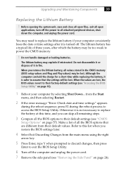
...sequence, press F2 during the reboot process to all attached peripheral devices, shut down the computer, and unplug the power cord. from their default values. Refer to this time, and you restore the BIOS settings later. 4 Select Exit Discarding Changes from the main menu using the right arrow...type Y when prompted to discard changes, then press Enter to assume that are lost, the BIOS values revert to their default settings (see "CMOS Setup Options" on page 16). 1 Reboot your computer consistently loses the date or time settings after which the battery may be too weak to ...
...sequence, press F2 during the reboot process to all attached peripheral devices, shut down the computer, and unplug the power cord. from their default values. Refer to this time, and you restore the BIOS settings later. 4 Select Exit Discarding Changes from the main menu using the right arrow...type Y when prompted to discard changes, then press Enter to assume that are lost, the BIOS values revert to their default settings (see "CMOS Setup Options" on page 16). 1 Reboot your computer consistently loses the date or time settings after which the battery may be too weak to ...
System Reference Manual
Page 49
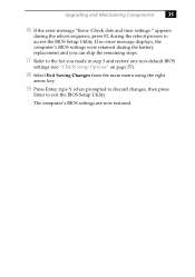
... battery replacement and you can skip the remaining steps. 17 Refer to the list you made in step 3 and restore any non-default BIOS settings (see "CMOS Setup Options" on page 57). 18 Select Exit Saving Changes from the main menu using the right arrow key. ... type Y when prompted to discard changes, then press Enter to access the BIOS Setup Utility. If no error message displays, the computer's BIOS settings were retained during the reboot process to exit the BIOS Setup Utility. The computer's BIOS settings are now restored. Upgrading and Maintaining Components 35 16 If the error message...
... battery replacement and you can skip the remaining steps. 17 Refer to the list you made in step 3 and restore any non-default BIOS settings (see "CMOS Setup Options" on page 57). 18 Select Exit Saving Changes from the main menu using the right arrow key. ... type Y when prompted to discard changes, then press Enter to access the BIOS Setup Utility. If no error message displays, the computer's BIOS settings were retained during the reboot process to exit the BIOS Setup Utility. The computer's BIOS settings are now restored. Upgrading and Maintaining Components 35 16 If the error message...
System Reference Manual
Page 53
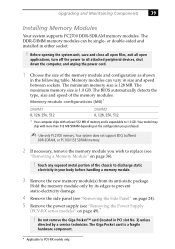
...size is 1.0 GB. The maximum memory size is 128 MB. The BIOS automatically detects the type, size and speed of the chassis to all... 24). 5 Remove the power supply (see "Removing a Memory Module" on the configuration you wish to PCV-RX models only. or double-sided and installed in size and speed between sockets. Upgrading and Maintaining Components 39... service technician. Memory module configurations (MB)* DIMM1 0, 128, 256, 512 DIMM2 0, 128, 256, 512 * Your computer ships with more than 512 MB SDRAM depending on page 36). ! Before opening the system unit, save and close all...
...size is 1.0 GB. The maximum memory size is 128 MB. The BIOS automatically detects the type, size and speed of the chassis to all... 24). 5 Remove the power supply (see "Removing a Memory Module" on the configuration you wish to PCV-RX models only. or double-sided and installed in size and speed between sockets. Upgrading and Maintaining Components 39... service technician. Memory module configurations (MB)* DIMM1 0, 128, 256, 512 DIMM2 0, 128, 256, 512 * Your computer ships with more than 512 MB SDRAM depending on page 36). ! Before opening the system unit, save and close all...
System Reference Manual
Page 69
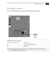
CLR CMOS 123 CLR CMOS Jumper Settings Jumper Plug Position 1-2 2-3 Function Clear CMOS Password Normal ✍ The configuration jumpers should never need changing unless otherwise directed by a technical support or service technician. System Board 55 CLR CMOS Jumper The CLR CMOS Jumper clears the BIOS password setting.
CLR CMOS 123 CLR CMOS Jumper Settings Jumper Plug Position 1-2 2-3 Function Clear CMOS Password Normal ✍ The configuration jumpers should never need changing unless otherwise directed by a technical support or service technician. System Board 55 CLR CMOS Jumper The CLR CMOS Jumper clears the BIOS password setting.
System Reference Manual
Page 71
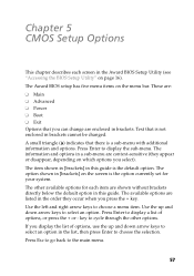
...option in brackets. Chapter 5 CMOS Setup Options This chapter describes each item are context-sensitive (they occur when you press the + key. The Award BIOS setup has five menu items on page 16). These are: ❑ Main ❑ Advanced ❑ Power ❑ Boot ❑ Exit Options ...for your system. The information and options in a sub-menu are shown without brackets directly below the default option in the Award BIOS Setup Utility (see "Accessing the BIOS Setup Utility" on the menu bar. A small triangle ( ) indicates that is the default option. key to choose a menu ...
...option in brackets. Chapter 5 CMOS Setup Options This chapter describes each item are context-sensitive (they occur when you press the + key. The Award BIOS setup has five menu items on page 16). These are: ❑ Main ❑ Advanced ❑ Power ❑ Boot ❑ Exit Options ...for your system. The information and options in a sub-menu are shown without brackets directly below the default option in the Award BIOS Setup Utility (see "Accessing the BIOS Setup Utility" on the menu bar. A small triangle ( ) indicates that is the default option. key to choose a menu ...
System Reference Manual
Page 73
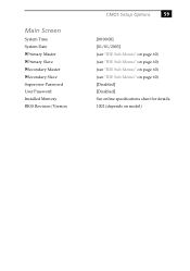
Main Screen System Time System Date Primary Master Primary Slave Secondary Master Secondary Slave Supervisor Password User Password Installed Memory BIOS Revision/Version CMOS Setup Options 59 [00:00:00] [01/01/2003] (see "IDE Sub-Menus" on page 60) (see "IDE Sub-Menus" on page 60) (see "IDE Sub-Menus" on page 60) (see "IDE Sub-Menus" on page 60) [Disabled] [Disabled] See online specifications sheet for details. 1002 (depends on model)
Main Screen System Time System Date Primary Master Primary Slave Secondary Master Secondary Slave Supervisor Password User Password Installed Memory BIOS Revision/Version CMOS Setup Options 59 [00:00:00] [01/01/2003] (see "IDE Sub-Menus" on page 60) (see "IDE Sub-Menus" on page 60) (see "IDE Sub-Menus" on page 60) (see "IDE Sub-Menus" on page 60) [Disabled] [Disabled] See online specifications sheet for details. 1002 (depends on model)
System Reference Manual
Page 95
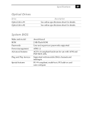
See online specifications sheet for details. Optical Drives Drive Optical drive #1 Optical drive #2 Specifications 81 Description See online specifications sheet for details. System BIOS Make and model ROM Passwords Power management Advanced features Plug and Play devices Special features Award-based 2 Mb Flash-ROM User and supervisor passwords supported APM 1.2 ACPI-1.0 compliant hardware for use with APM and PNP BIOS APIs Supported with steerable DMA channels and interrupts PC-99 compliant, multi-boot, PCI add-on card auto-configure
See online specifications sheet for details. Optical Drives Drive Optical drive #1 Optical drive #2 Specifications 81 Description See online specifications sheet for details. System BIOS Make and model ROM Passwords Power management Advanced features Plug and Play devices Special features Award-based 2 Mb Flash-ROM User and supervisor passwords supported APM 1.2 ACPI-1.0 compliant hardware for use with APM and PNP BIOS APIs Supported with steerable DMA channels and interrupts PC-99 compliant, multi-boot, PCI add-on card auto-configure

System Reference Manual
Page 97
... graphics specifications 78 H hard drive specifications 80 83 See slots F fax/modem - See lithium battery beep codes 69 BIOS Setup Utility See CMOS Setup Utility BIOS setup utility advanced screen 61 boot screen 64 exit screen 65 main screen 59 options 57 power screen 63 screens 57... BIOS specifications 81 C chipset specifications 77 CLR CMOS Jumper 55 CMOS - See Also BIOS CMOS Setup Utility 16 codes, beeps 69 communications, specifications 79 computer lithium battery ix configuring power management 17 connectors i.LINK 6 monitor ...
... graphics specifications 78 H hard drive specifications 80 83 See slots F fax/modem - See lithium battery beep codes 69 BIOS Setup Utility See CMOS Setup Utility BIOS setup utility advanced screen 61 boot screen 64 exit screen 65 main screen 59 options 57 power screen 63 screens 57... BIOS specifications 81 C chipset specifications 77 CLR CMOS Jumper 55 CMOS - See Also BIOS CMOS Setup Utility 16 codes, beeps 69 communications, specifications 79 computer lithium battery ix configuring power management 17 connectors i.LINK 6 monitor ...
System Reference Manual
Page 99
See I/O slot slot cover, removing 42 specifications AGP bus 77 audio 79 BIOS 81 chipset 77 communications 79 floppy disk drive and controller 80 Giga Pocket 79 graphics 78 hard drives and controllers 80 I/O and expansion slots 80 L2 cache 78 memory configurations 78 memory module 78 PCI bus 78 processor 77, 78 status and error messages 70 supervisor password 68 system board CLR CMOS Jumper 55 memory module connector 52 power connector 53 system I/O address map 73 system memory, installing 39 U USB connectors 6 user password 68 Index 85 S See Also communications slot -
See I/O slot slot cover, removing 42 specifications AGP bus 77 audio 79 BIOS 81 chipset 77 communications 79 floppy disk drive and controller 80 Giga Pocket 79 graphics 78 hard drives and controllers 80 I/O and expansion slots 80 L2 cache 78 memory configurations 78 memory module 78 PCI bus 78 processor 77, 78 status and error messages 70 supervisor password 68 system board CLR CMOS Jumper 55 memory module connector 52 power connector 53 system I/O address map 73 system memory, installing 39 U USB connectors 6 user password 68 Index 85 S See Also communications slot -
Online Help Center (VAIO User Guide)
Page 51
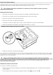
... stored in household or business trash may become inaccurate. If you , visit the Sony Computing Support Web site at http://www.sony.com/pcsupport. Replacing the lithium battery 1. Write down your computer and turn off all peripheral devices, such as desired. If necessary, remove any ... then click OK. Page 51 Installing a lithium battery (PCV- Double-click the time readout displayed in the BIOS Setup utility. 2. Remove the side panel. From the Date & Time tab, change the settings as your nearest Sony Service Center or Factory Service Center. Replace the battery only...
... stored in household or business trash may become inaccurate. If you , visit the Sony Computing Support Web site at http://www.sony.com/pcsupport. Replacing the lithium battery 1. Write down your computer and turn off all peripheral devices, such as desired. If necessary, remove any ... then click OK. Page 51 Installing a lithium battery (PCV- Double-click the time readout displayed in the BIOS Setup utility. 2. Remove the side panel. From the Date & Time tab, change the settings as your nearest Sony Service Center or Factory Service Center. Replace the battery only...


