Quick Start Guide
Page 44
...are adjusted correctly. (See the manual that came with a floppy disk drive. VAIO Digital Studio Computer Quick Start About VAIO Computer Functions My computer does not start. ❑ Verify that the computer is plugged into a power source and turned on. The Windows Task Manager window appears. 2 From the ... or contrast control dials are connected firmly. ❑ If you plugged the computer into a power strip or Uninterruptible Power Supply (UPS), make sure the power strip or UPS is turned on and working. ❑ Verify that the computer is not in monitor, confirm that it is turned on.
...are adjusted correctly. (See the manual that came with a floppy disk drive. VAIO Digital Studio Computer Quick Start About VAIO Computer Functions My computer does not start. ❑ Verify that the computer is plugged into a power source and turned on. The Windows Task Manager window appears. 2 From the ... or contrast control dials are connected firmly. ❑ If you plugged the computer into a power strip or Uninterruptible Power Supply (UPS), make sure the power strip or UPS is turned on and working. ❑ Verify that the computer is not in monitor, confirm that it is turned on.
System Reference Manual
Page 12
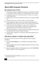
... Drive 44 To identify additional hard disk space 48 Removing the Power Supply (PCV-RX series models 49 Replacing the Power Supply (PCV-RX series model 50 Chapter 4 - System Board 51 Memory Module (DDR-DIMM) Slots 52 Power Supply and Aux Power Headers 53 CLR CMOS Jumper 55 Chapter 5 - CMOS Setup ...Options 57 Main Screen 59 Advanced Screen 61 Power Screen 63 Boot Screen 64 Exit Screen 65 xii VAIO ...
... Drive 44 To identify additional hard disk space 48 Removing the Power Supply (PCV-RX series models 49 Replacing the Power Supply (PCV-RX series model 50 Chapter 4 - System Board 51 Memory Module (DDR-DIMM) Slots 52 Power Supply and Aux Power Headers 53 CLR CMOS Jumper 55 Chapter 5 - CMOS Setup ...Options 57 Main Screen 59 Advanced Screen 61 Power Screen 63 Boot Screen 64 Exit Screen 65 xii VAIO ...
System Reference Manual
Page 35
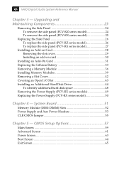
Configuring Your System 21 8 Click the UPS tab. For more information about configuring a UPS device, refer to select and configure an Uninterruptible Power Supply (UPS) device for your system. ✍ A UPS device is an optional accessory not supplied with your system. 9 Select the settings most appropriate for your system and click OK. The UPS tab enables you to the Microsoft® Windows® XP operating system Help.
Configuring Your System 21 8 Click the UPS tab. For more information about configuring a UPS device, refer to select and configure an Uninterruptible Power Supply (UPS) device for your system. ✍ A UPS device is an optional accessory not supplied with your system. 9 Select the settings most appropriate for your system and click OK. The UPS tab enables you to the Microsoft® Windows® XP operating system Help.
System Reference Manual
Page 38
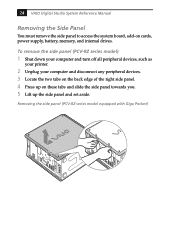
24 VAIO Digital Studio System Reference Manual Removing the Side Panel You must remove the side panel to access the system board, add-on these tabs and slide the side panel towards you. 5 Lift up the side panel and set aside. Removing the side panel (PCV-RZ series model equipped... remove the side panel (PCV-RZ series model) 1 Shut down your computer and turn off all peripheral devices, such as your printer. 2 Unplug your computer and disconnect any peripheral devices. 3 Locate the two tabs on the back edge of the right side panel. 4 Press up on cards, power supply, battery, memory, and ...
24 VAIO Digital Studio System Reference Manual Removing the Side Panel You must remove the side panel to access the system board, add-on these tabs and slide the side panel towards you. 5 Lift up the side panel and set aside. Removing the side panel (PCV-RZ series model equipped... remove the side panel (PCV-RZ series model) 1 Shut down your computer and turn off all peripheral devices, such as your printer. 2 Unplug your computer and disconnect any peripheral devices. 3 Locate the two tabs on the back edge of the right side panel. 4 Press up on cards, power supply, battery, memory, and ...
System Reference Manual
Page 50
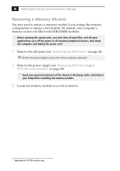
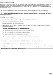
... you change the memory configuration or replace a bad module. 36 VAIO Digital Studio System Reference Manual Removing a Memory Module You may need to remove a memory module if you wish to remove. * Applicable to PCV-RX models only. Before opening the system unit, save and close... off the power to all attached peripheral devices, shut down the computer, and unplug the power cord. 1 Remove the side panel (see "Removing the Side Panel" on page 24). ✍ Remove the power supply to access the memory modules underneath.* 2 Remove the power supply (see "Removing the Power Supply (PCV-RX series ...
... you change the memory configuration or replace a bad module. 36 VAIO Digital Studio System Reference Manual Removing a Memory Module You may need to remove a memory module if you wish to remove. * Applicable to PCV-RX models only. Before opening the system unit, save and close... off the power to all attached peripheral devices, shut down the computer, and unplug the power cord. 1 Remove the side panel (see "Removing the Side Panel" on page 24). ✍ Remove the power supply to access the memory modules underneath.* 2 Remove the power supply (see "Removing the Power Supply (PCV-RX series ...
System Reference Manual
Page 52
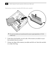
Store the module in a static-free bag. 38 VAIO Digital Studio System Reference Manual Removing a memory module (PCV-RX series model) ✍ The memory modules are located beneath the power supply (applicable to PCV-RX models only). 4 Push down the handle on each side of the memory module to eject the module from its socket. 5 Grasp one edge of the memory module and lift out.
Store the module in a static-free bag. 38 VAIO Digital Studio System Reference Manual Removing a memory module (PCV-RX series model) ✍ The memory modules are located beneath the power supply (applicable to PCV-RX models only). 4 Push down the handle on each side of the memory module to eject the module from its socket. 5 Grasp one edge of the memory module and lift out.
System Reference Manual
Page 53
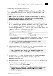
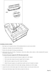
..., shut down the computer, and unplug the power cord. 1 Choose the size of the memory modules. or double-sided and installed in your body before handling a memory module. 3 Remove the new memory module(s) from its edges to replace (see "Removing the Power Supply (PCV-RX series models)" ...on the configuration you wish to prevent static-electricity damage. 4 Remove the side panel (see "Removing the Side Panel" on page 24). 5 Remove the power supply (see "Removing a Memory Module" on page 36). !...
..., shut down the computer, and unplug the power cord. 1 Choose the size of the memory modules. or double-sided and installed in your body before handling a memory module. 3 Remove the new memory module(s) from its edges to replace (see "Removing the Power Supply (PCV-RX series models)" ...on the configuration you wish to prevent static-electricity damage. 4 Remove the side panel (see "Removing the Side Panel" on page 24). 5 Remove the power supply (see "Removing a Memory Module" on page 36). !...
System Reference Manual
Page 55
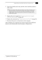
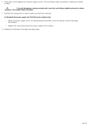
... place. 9 Replace the power supply (see "Replacing the Power Supply (PCV-RX series model)" on page 50).* 10 Replace the side panel (see "Replacing the Side Panel" on page 26). 11 Reconnect the power cord and turn on each side are not totally straight upright, continue to PCV-RX models only. Upgrading ...and Maintaining Components 41 8 Press down on each side of the module until the module is fully seated. ✍ When the module is fully seated, the handles on each side of the module. After restarting your computer, the system ...
... place. 9 Replace the power supply (see "Replacing the Power Supply (PCV-RX series model)" on page 50).* 10 Replace the side panel (see "Replacing the Side Panel" on page 26). 11 Reconnect the power cord and turn on each side are not totally straight upright, continue to PCV-RX models only. Upgrading ...and Maintaining Components 41 8 Press down on each side of the module until the module is fully seated. ✍ When the module is fully seated, the handles on each side of the module. After restarting your computer, the system ...
System Reference Manual
Page 59
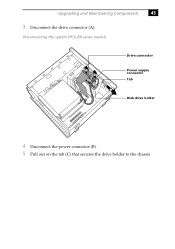
Upgrading and Maintaining Components 45 3 Disconnect the drive connector (A). Disconnecting the system (PCV-RX series model) A B C Drive connector Power supply connector Tab Disk drive holder 4 Disconnect the power connector (B). 5 Pull out on the tab (C) that secures the drive holder to the chassis.
Upgrading and Maintaining Components 45 3 Disconnect the drive connector (A). Disconnecting the system (PCV-RX series model) A B C Drive connector Power supply connector Tab Disk drive holder 4 Disconnect the power connector (B). 5 Pull out on the tab (C) that secures the drive holder to the chassis.
System Reference Manual
Page 63
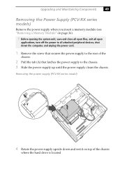
... of the chassis. 2 Pull the tab (A) that latches the power supply to the chassis. 3 Slide the power supply up until the power supply clears the chassis. Removing the power supply (PCV-RX series model) A 4 Rotate the power supply upside down the computer, and unplug the power cord. 1 Remove the screw that secures the power supply to the rear of the chassis where the hard drive...
... of the chassis. 2 Pull the tab (A) that latches the power supply to the chassis. 3 Slide the power supply up until the power supply clears the chassis. Removing the power supply (PCV-RX series model) A 4 Rotate the power supply upside down the computer, and unplug the power cord. 1 Remove the screw that secures the power supply to the rear of the chassis where the hard drive...
System Reference Manual
Page 64
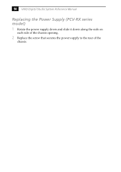
50 VAIO Digital Studio System Reference Manual Replacing the Power Supply (PCV-RX series model) 1 Rotate the power supply down and slide it down along the rails on each side of the chassis opening. 2 Replace the screw that secures the power supply to the rear of the chassis.
50 VAIO Digital Studio System Reference Manual Replacing the Power Supply (PCV-RX series model) 1 Rotate the power supply down and slide it down along the rails on each side of the chassis opening. 2 Replace the screw that secures the power supply to the rear of the chassis.
System Reference Manual
Page 65
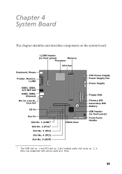
..., Line Out CD-In Aux-In Slot No. 1 (CNR)* Slot No. 2 (PCI)* Slot No. 3 (PCI) Slot No. 4 (PCI) Slot No. 5 (AGP) CMOS Clear CPU Power Supply Power Supply Fan Power Supply Floppy Disk Primary IDE Secondary IDE Battery USB Header (to front panel) Front Panel Header * The CNR slot no. 1 and PCI slot no. 2 are located...
..., Line Out CD-In Aux-In Slot No. 1 (CNR)* Slot No. 2 (PCI)* Slot No. 3 (PCI) Slot No. 4 (PCI) Slot No. 5 (AGP) CMOS Clear CPU Power Supply Power Supply Fan Power Supply Floppy Disk Primary IDE Secondary IDE Battery USB Header (to front panel) Front Panel Header * The CNR slot no. 1 and PCI slot no. 2 are located...
System Reference Manual
Page 67
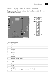
System Board 53 Power Supply and Aux Power Headers The power supply header on the system board connects to the power supply header labelled P1. 2 4 1 3 10 20 1 11 Power Supply header Pin Signal Name 1 +3.3 V 2 +3.3 V 3 Ground 4 +5 V 5 Ground 6 +5 V 7 Ground 8 PWRGD (Power Good) 9 +5 VSB 10 +12 V 11 +3.3 V 12 -12 V 13 Ground 14 PS-ON# (power supply remote on/off control) 15 Ground
System Board 53 Power Supply and Aux Power Headers The power supply header on the system board connects to the power supply header labelled P1. 2 4 1 3 10 20 1 11 Power Supply header Pin Signal Name 1 +3.3 V 2 +3.3 V 3 Ground 4 +5 V 5 Ground 6 +5 V 7 Ground 8 PWRGD (Power Good) 9 +5 VSB 10 +12 V 11 +3.3 V 12 -12 V 13 Ground 14 PS-ON# (power supply remote on/off control) 15 Ground
System Reference Manual
Page 68
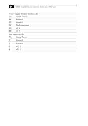
54 VAIO Digital Studio System Reference Manual Power Supply header (Continued) Pin Signal Name 16 Ground 17 Ground 18 No Connection 19 +5 V 20 +5 V Aux Power header Pin Signal Name 1 Ground 2 Ground 3 +12 V 4 +12 V
54 VAIO Digital Studio System Reference Manual Power Supply header (Continued) Pin Signal Name 16 Ground 17 Ground 18 No Connection 19 +5 V 20 +5 V Aux Power header Pin Signal Name 1 Ground 2 Ground 3 +12 V 4 +12 V
Online Help Center (VAIO User Guide)
Page 36
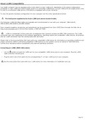
...or 6-pin i.LINK port on operating conditions and proper connection. About i.LINK Compatibility Your VAIO® computer may be purchased from Sony VAIO Direct through the Web site at http://vaio.sonystyle.com or the toll-free number, 1-888-315-7669. The i.LINK connection may.... A 6-pin i.LINK port can be equipped with your compatible i.LINK device for use . The total power supplied by the 6-pin i.LINK port cannot exceed 6 watts. Sony computer supplies, accessories, and peripherals can supply power (10V to 12V) to a connected i.LINK device. Connecting an i.LINK (IEEE 1394) device 1. Page...
...or 6-pin i.LINK port on operating conditions and proper connection. About i.LINK Compatibility Your VAIO® computer may be purchased from Sony VAIO Direct through the Web site at http://vaio.sonystyle.com or the toll-free number, 1-888-315-7669. The i.LINK connection may.... A 6-pin i.LINK port can be equipped with your compatible i.LINK device for use . The total power supplied by the 6-pin i.LINK port cannot exceed 6 watts. Sony computer supplies, accessories, and peripherals can supply power (10V to 12V) to a connected i.LINK device. Connecting an i.LINK (IEEE 1394) device 1. Page...
Online Help Center (VAIO User Guide)
Page 48
...m em ory (PCV- Pull the tab that secures the power supply unit to the chassis. 2. See the online specifications sheet for PCV-RX series model only) 1. Gently handle the memory module by the sides only. Slide the power supply unit up until it out. Push down your computer and turn off ...all peripheral devices, such as your computer. Shut down on the latches, located ...
...m em ory (PCV- Pull the tab that secures the power supply unit to the chassis. 2. See the online specifications sheet for PCV-RX series model only) 1. Gently handle the memory module by the sides only. Slide the power supply unit up until it out. Push down your computer and turn off ...all peripheral devices, such as your computer. Shut down on the latches, located ...
Online Help Center (VAIO User Guide)
Page 49
.... 3. If necessary, remove any cables, add-on cards, or other components to an upside down your computer and turn off all peripheral devices, such as your computer and any peripheral devices. 3. Slide the power supply unit up until it by the the edges. 6. Locate the notch on its anti-static package, handling ...of the module to the chassis. 2. Gently place the unit on the bottom edge of the memory module into the slot. To remove the power supply (for PCV-RX series model only) 1. Remove the side panel. Rotate the power supply to access the memory module slots. Page 49
.... 3. If necessary, remove any cables, add-on cards, or other components to an upside down your computer and turn off all peripheral devices, such as your computer and any peripheral devices. 3. Slide the power supply unit up until it by the the edges. 6. Locate the notch on its anti-static package, handling ...of the module to the chassis. 2. Gently place the unit on the bottom edge of the memory module into the slot. To remove the power supply (for PCV-RX series model only) 1. Remove the side panel. Rotate the power supply to access the memory module slots. Page 49
Online Help Center (VAIO User Guide)
Page 50
...slightly outward to the chassis. 10. The module clicks into position, holding the module in place. To Reinstall the power supply (for PCV-RX series models only) 1. Replace the screw that secures the power supply to relieve pressure. Page 50 The end latches snap into place. 9. See About the Side Panel. Press down ...evenly against the module's upper corners. Reinstall any components or add-on cards you may have removed. Replace the side panel. Rotate the power supply unit to its original position and slide it into the chassis until the tab snaps into position. 2. 8.
...slightly outward to the chassis. 10. The module clicks into position, holding the module in place. To Reinstall the power supply (for PCV-RX series models only) 1. Replace the screw that secures the power supply to relieve pressure. Page 50 The end latches snap into place. 9. See About the Side Panel. Press down ...evenly against the module's upper corners. Reinstall any components or add-on cards you may have removed. Replace the side panel. Rotate the power supply unit to its original position and slide it into the chassis until the tab snaps into position. 2. 8.
Online Help Center (VAIO User Guide)
Page 65
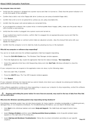
... not shut down your computer does not respond or the application does not close the application. The Windows operating system may result in the loss of the dialog box. 3. Click Start in monitor, confirm that it is plugged into a power strip or Uninterruptible Power Supply (UPS), make sure the power strip or UPS is turned...
... not shut down your computer does not respond or the application does not close the application. The Windows operating system may result in the loss of the dialog box. 3. Click Start in monitor, confirm that it is plugged into a power strip or Uninterruptible Power Supply (UPS), make sure the power strip or UPS is turned...
Online Help Center (VAIO User Guide)
Page 79
...data during an electrical storm. If you live in an area that may result in the power supply. Never pull the cord itself. Unplug your computer from the wall outlet or power strip. Do not place heavy objects on 100-120 V AC 50/60 Hz only. ... damage to purchase an Uninterruptible Power Supply (UPS). This protects you against internal components that experiences frequent power fluctuations, you do not intend to open the power supply. To remove power from the system, you must turn off the computer and then unplug the AC power cord from the wall outlet if...
...data during an electrical storm. If you live in an area that may result in the power supply. Never pull the cord itself. Unplug your computer from the wall outlet or power strip. Do not place heavy objects on 100-120 V AC 50/60 Hz only. ... damage to purchase an Uninterruptible Power Supply (UPS). This protects you against internal components that experiences frequent power fluctuations, you do not intend to open the power supply. To remove power from the system, you must turn off the computer and then unplug the AC power cord from the wall outlet if...


