Quick Start Guide
Page 16
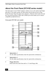
...Floppy disk drive Reads and writes data from and to the optical and floppy disk drives. VAIO Digital Studio Computer Quick Start About the Front Panel (PCV-RZ series model) The front panel of your VAIO Computer enables access to a 3.5-inch floppy disk. 16 On certain models, the front panel also... provides access to Giga Pocket Personal Video Recorder jacks and ports, a Memory Stick media slot and the Universal Serial Bus (USB), and ...
...Floppy disk drive Reads and writes data from and to the optical and floppy disk drives. VAIO Digital Studio Computer Quick Start About the Front Panel (PCV-RZ series model) The front panel of your VAIO Computer enables access to a 3.5-inch floppy disk. 16 On certain models, the front panel also... provides access to Giga Pocket Personal Video Recorder jacks and ports, a Memory Stick media slot and the Universal Serial Bus (USB), and ...
Quick Start Guide
Page 18
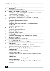
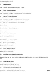
VAIO Digital Studio Computer Quick Start 14 Floppy disk eject button Ejects a floppy disk from the floppy disk drive. 15 Universal Serial Bus (USB 2.0) ports (2) Connections for compatible high/full/low-speed USB devices. 16 i.LINK (4-pin) S400 port (IEEE 1394) Connection for information on the software ...may not communicate with your compatible i.LINK device for a compatible digital device. ✍ i.LINK is a trademark of Sony used only to your system, such as an optical or hard disk drive, confirm their operating system compatibility and required operating conditions. 18
VAIO Digital Studio Computer Quick Start 14 Floppy disk eject button Ejects a floppy disk from the floppy disk drive. 15 Universal Serial Bus (USB 2.0) ports (2) Connections for compatible high/full/low-speed USB devices. 16 i.LINK (4-pin) S400 port (IEEE 1394) Connection for information on the software ...may not communicate with your compatible i.LINK device for a compatible digital device. ✍ i.LINK is a trademark of Sony used only to your system, such as an optical or hard disk drive, confirm their operating system compatibility and required operating conditions. 18
Quick Start Guide
Page 19
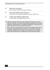
The icons on the back panel locate and identify the ports on your computer contains the ports for a parallel device, such as a printer or scanner. 19 VIDEO1 INPUT - VIDEO OUTPUT - - VHF/UHF PHONE LINE 1 AC Input port ... Keyboard port Connection for a PS/2 keyboard. 4 Printer port Connection for supplied and optional accessories. About the Back Panel (PCV-RZ series model) About the Back Panel (PCV-RZ series model) The back panel of your computer. Back panel (PCV-RZ series model) MONITOR USB MIC HEADPHONES LINE IN MONITOR AUDIO S VIDEO/VIDEO AUDIO S VIDEO/VIDEO -
The icons on the back panel locate and identify the ports on your computer contains the ports for a parallel device, such as a printer or scanner. 19 VIDEO1 INPUT - VIDEO OUTPUT - - VHF/UHF PHONE LINE 1 AC Input port ... Keyboard port Connection for a PS/2 keyboard. 4 Printer port Connection for supplied and optional accessories. About the Back Panel (PCV-RZ series model) About the Back Panel (PCV-RZ series model) The back panel of your computer. Back panel (PCV-RZ series model) MONITOR USB MIC HEADPHONES LINE IN MONITOR AUDIO S VIDEO/VIDEO AUDIO S VIDEO/VIDEO -
Quick Start Guide
Page 20
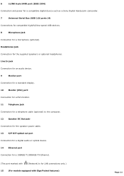
... Audio Out jack Connection for the supplied speakers or optional headphones. Headphones jack Connection for an audio cable (supplied). VAIO Digital Studio Computer Quick Start 5 Monitor port* Connection for a standard display. 6 i.LINK 6-pin S400 port (IEEE 1394) Connection... and power for a compatible digital device such as a Sony Digital Handycam® camcorder. 7 Universal Serial Bus (USB 2.0) ports (4) Connections for compatible high/full/low-speed USB ...
... Audio Out jack Connection for the supplied speakers or optional headphones. Headphones jack Connection for an audio cable (supplied). VAIO Digital Studio Computer Quick Start 5 Monitor port* Connection for a standard display. 6 i.LINK 6-pin S400 port (IEEE 1394) Connection... and power for a compatible digital device such as a Sony Digital Handycam® camcorder. 7 Universal Serial Bus (USB 2.0) ports (4) Connections for compatible high/full/low-speed USB ...
Quick Start Guide
Page 26
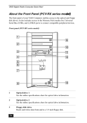
... Memory Stick media slot, Universal Serial Bus (USB), and i.LINK® ports to the optical and floppy disk drives. VAIO Digital Studio Computer Quick Start About the Front Panel (PCV-RX series model) The front panel of your VAIO Computer enables access to connect compatible peripheral devices. Front panel (PCV-RX series model) 1 Optical drive 1 See the...
... Memory Stick media slot, Universal Serial Bus (USB), and i.LINK® ports to the optical and floppy disk drives. VAIO Digital Studio Computer Quick Start About the Front Panel (PCV-RX series model) The front panel of your VAIO Computer enables access to connect compatible peripheral devices. Front panel (PCV-RX series model) 1 Optical drive 1 See the...
Quick Start Guide
Page 27
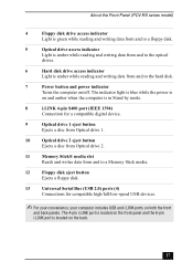
... i.LINK port is located on both the front and back panels. The indicator light is blue while the power is on and amber when the computer is in Stand by mode. 8 i.LINK 4-pin S400 port (IEEE 1394) Connection for a compatible digital device. 9 Optical drive 1 eject ...eject button Ejects a floppy disk. 13 Universal Serial Bus (USB 2.0) ports (4) Connections for compatible high/full/low-speed USB devices. ✍ For your convenience, your computer includes USB and i.LINK ports on the back. 27 About the Front Panel (PCV-RX series model) 4 Floppy disk drive access indicator Light is...
... i.LINK port is located on both the front and back panels. The indicator light is blue while the power is on and amber when the computer is in Stand by mode. 8 i.LINK 4-pin S400 port (IEEE 1394) Connection for a compatible digital device. 9 Optical drive 1 eject ...eject button Ejects a floppy disk. 13 Universal Serial Bus (USB 2.0) ports (4) Connections for compatible high/full/low-speed USB devices. ✍ For your convenience, your computer includes USB and i.LINK ports on the back. 27 About the Front Panel (PCV-RX series model) 4 Floppy disk drive access indicator Light is...
Quick Start Guide
Page 29
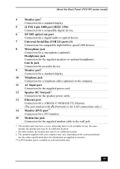
... standard display. 10 Telephone jack Connection for a telephone cable (optional) to the computer. 11 AC Input port Connection for the supplied power cord. 12 Speaker DC Out... the system purchased. Headphones jack Connection for a microphone (optional). About the Back Panel (PCV-RX series model) 4 Monitor port* Connection for a standard display. 5 i.LINK 6-pin... for a digital audio or optical device. 7 Universal Serial Bus (USB 2.0) ports (4) Connections for compatible high/full/low-speed USB devices. 8 Microphone jack Connection for the supplied speakers or optional headphones...
... standard display. 10 Telephone jack Connection for a telephone cable (optional) to the computer. 11 AC Input port Connection for the supplied power cord. 12 Speaker DC Out... the system purchased. Headphones jack Connection for a microphone (optional). About the Back Panel (PCV-RX series model) 4 Monitor port* Connection for a standard display. 5 i.LINK 6-pin... for a digital audio or optical device. 7 Universal Serial Bus (USB 2.0) ports (4) Connections for compatible high/full/low-speed USB devices. 8 Microphone jack Connection for the supplied speakers or optional headphones...
Quick Start Guide
Page 34
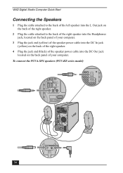
VAIO Digital Studio Computer Quick Start Connecting the Speakers 1 Plug the cable attached to the back of the left speaker into the L Out jack on ...the right speaker. 2 Plug the cable attached to the back of the right speaker into the Headphones jack, located on the back panel of your computer. 3 Plug the jack end (yellow) of the speaker power cable into the DC In jack (yellow) on the back of the right speaker... 4 Plug the jack end (black) of the speaker power cable into the DC Out jack located on the back panel of your computer. To connect the PCVA-SP4 speakers (PCV-RZ series model) USB 4 34
VAIO Digital Studio Computer Quick Start Connecting the Speakers 1 Plug the cable attached to the back of the left speaker into the L Out jack on ...the right speaker. 2 Plug the cable attached to the back of the right speaker into the Headphones jack, located on the back panel of your computer. 3 Plug the jack end (yellow) of the speaker power cable into the DC In jack (yellow) on the back of the right speaker... 4 Plug the jack end (black) of the speaker power cable into the DC Out jack located on the back panel of your computer. To connect the PCVA-SP4 speakers (PCV-RZ series model) USB 4 34

Quick Start Guide
Page 35
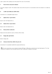
Connecting the Speakers To connect the PCVA-SP3A speakers (PCV-RX series model) USB NETWORK ACT LINK MIC HEADPHONES LINE IN 35
Connecting the Speakers To connect the PCVA-SP3A speakers (PCV-RX series model) USB NETWORK ACT LINK MIC HEADPHONES LINE IN 35

VAIO User Guide (primary manual)
Page 7
Front panel (PCV- On certain models, the front panel also provides access to Giga Pocket Personal Video Recorder jacks and ports, a Memory Stick media slot and the Universal Serial Bus (USB), and i.LINK® ports that enable you to a floppy disk. 5 Power indicator Light is blue while the power is on. 6 Power.... 4 Floppy disk drive access indicator Light is green while reading and writing data from and to connect compatible peripheral devices. About the Front Panel (PCV-RZ series model) The front panel of your VAIO Computer enables access to the optical and floppy disk drives.
Front panel (PCV- On certain models, the front panel also provides access to Giga Pocket Personal Video Recorder jacks and ports, a Memory Stick media slot and the Universal Serial Bus (USB), and i.LINK® ports that enable you to a floppy disk. 5 Power indicator Light is blue while the power is on. 6 Power.... 4 Floppy disk drive access indicator Light is green while reading and writing data from and to connect compatible peripheral devices. About the Front Panel (PCV-RZ series model) The front panel of your VAIO Computer enables access to the optical and floppy disk drives.
VAIO User Guide (primary manual)
Page 8
... indicator Reads and writes data from the floppy disk drive. 15 Universal Serial Bus (USB 2.0) ports (2) Connections for compatible high/full/low-speed USB devices. Turns the computer on and off. 7 Stand by indicator Light is red when the computer is placed in Stand by mode. 8 Optical drive access indicator Light is amber while...
... indicator Reads and writes data from the floppy disk drive. 15 Universal Serial Bus (USB 2.0) ports (2) Connections for compatible high/full/low-speed USB devices. Turns the computer on and off. 7 Stand by indicator Light is red when the computer is placed in Stand by mode. 8 Optical drive access indicator Light is amber while...
VAIO User Guide (primary manual)
Page 11
...standard display. 10 Monitor (DVI) port3 Connection for a DVI monitor. 11 Telephone jack Connection for a telephone cable (optional) to the computer. 12 Speaker DC Out jack4 Connection for the speaker power cable. 13 S/P DIF optical out port Connection for a digital audio or ... 6 i.LINK 6-pin S400 port (IEEE 1394) Connection and power for a compatible digital device such as a Sony Digital Handycam® camcorder. 7 Universal Serial Bus (USB 2.0) ports (4) Connections for compatible high/full/low-speed USB devices. 8 Microphone jack Connection for a microphone (optional).
...standard display. 10 Monitor (DVI) port3 Connection for a DVI monitor. 11 Telephone jack Connection for a telephone cable (optional) to the computer. 12 Speaker DC Out jack4 Connection for the speaker power cable. 13 S/P DIF optical out port Connection for a digital audio or ... 6 i.LINK 6-pin S400 port (IEEE 1394) Connection and power for a compatible digital device such as a Sony Digital Handycam® camcorder. 7 Universal Serial Bus (USB 2.0) ports (4) Connections for compatible high/full/low-speed USB devices. 8 Microphone jack Connection for a microphone (optional).

VAIO User Guide (primary manual)
Page 17
About the Front Panel (PCV-RX series model) The front panel of your VAIO Computer enables access to the optical drives. 6 Hard disk drive access indicator Page 17 RX series m odel) 1 Optical drive 1 See the online specifications sheet for optical ... a floppy disk. 5 Optical drive access indicator Light is amber while reading and writing data from and to the optical and floppy disk drives. Front panel (PCV- It also includes access to the Memory Stick media slot, Universal Serial Bus (USB), and i.LINK® ports to connect compatible peripheral devices.
About the Front Panel (PCV-RX series model) The front panel of your VAIO Computer enables access to the optical drives. 6 Hard disk drive access indicator Page 17 RX series m odel) 1 Optical drive 1 See the online specifications sheet for optical ... a floppy disk. 5 Optical drive access indicator Light is amber while reading and writing data from and to the optical and floppy disk drives. Front panel (PCV- It also includes access to the Memory Stick media slot, Universal Serial Bus (USB), and i.LINK® ports to connect compatible peripheral devices.
VAIO User Guide (primary manual)
Page 18
...Stick media. 12 Floppy disk eject button Ejects a floppy disk. 13 Universal Serial Bus (USB 2.0) ports (4) Connections for compatible high/full/low-speed USB devices. Page 18 For your convenience, your computer includes USB and i.LINK ports on the back. The indicator light is blue while the power is... on and amber when the computer is amber while reading and writing data from and to...
...Stick media. 12 Floppy disk eject button Ejects a floppy disk. 13 Universal Serial Bus (USB 2.0) ports (4) Connections for compatible high/full/low-speed USB devices. Page 18 For your convenience, your computer includes USB and i.LINK ports on the back. The indicator light is blue while the power is... on and amber when the computer is amber while reading and writing data from and to...

VAIO User Guide (primary manual)
Page 20
...audio device. 9 Monitor port2 Connection for a standard display. 10 Telephone jack Connection for a telephone cable (optional) to the computer. 11 AC Input port Connection for the supplied power cord. 12 Speaker DC Out jack3 Connection for the speaker power cable..... 15 Modem line jack Connection for us e. Connection for a digital audio or optical device. 7 Universal Serial Bus (USB 2.0) ports (4) Connections for compatible high/full/low-speed USB devices. 8 Microphone jack Connection for the supplied speakers or optional headphones. O n s ome models , the monitor port...
...audio device. 9 Monitor port2 Connection for a standard display. 10 Telephone jack Connection for a telephone cable (optional) to the computer. 11 AC Input port Connection for the supplied power cord. 12 Speaker DC Out jack3 Connection for the speaker power cable..... 15 Modem line jack Connection for us e. Connection for a digital audio or optical device. 7 Universal Serial Bus (USB 2.0) ports (4) Connections for compatible high/full/low-speed USB devices. 8 Microphone jack Connection for the supplied speakers or optional headphones. O n s ome models , the monitor port...
VAIO User Guide (primary manual)
Page 72
...CD(s) for left-hand use an appropriate surface to easily-scratched surfaces by turning the ring counter-clockwise. See Reinstalling device drivers using a USB mouse, verify that the mouse is plugged securely into the mouse port. Click Printers and Other Hardware, then click Mouse. The Mouse ...work properly? Check that the keyboard1is securely plugged into the keyboard port. Save and close all applications, and turn off your computer. Turn the mouse upside down. Remove the mouse ball cover on the back of the mouse by turning clockwise the ring ...
...CD(s) for left-hand use an appropriate surface to easily-scratched surfaces by turning the ring counter-clockwise. See Reinstalling device drivers using a USB mouse, verify that the mouse is plugged securely into the mouse port. Click Printers and Other Hardware, then click Mouse. The Mouse ...work properly? Check that the keyboard1is securely plugged into the keyboard port. Save and close all applications, and turn off your computer. Turn the mouse upside down. Remove the mouse ball cover on the back of the mouse by turning clockwise the ring ...

VAIO User Guide (primary manual)
Page 77
... OK. Page 77 Select the appropriate port, usually LPT1, and then click Next. 6. Some printers do I install a printer? Connect your USB or IEEE 1394 printer to print a test page and complete printer installation. Place a check mark in the Windows taskbar, then click Control Panel. 2. ... off for approximately 10 seconds, and then turning it back on. If your printer does not resume normal operations, try restarting your computer. 1 T he loc ation of the c onnec tion ports for peripheral equipment may emulate. About Using Peripheral Equipment How do not function properly...
... OK. Page 77 Select the appropriate port, usually LPT1, and then click Next. 6. Some printers do I install a printer? Connect your USB or IEEE 1394 printer to print a test page and complete printer installation. Place a check mark in the Windows taskbar, then click Control Panel. 2. ... off for approximately 10 seconds, and then turning it back on. If your printer does not resume normal operations, try restarting your computer. 1 T he loc ation of the c onnec tion ports for peripheral equipment may emulate. About Using Peripheral Equipment How do not function properly...

