
Quick Start Guide
Page 20
...Apply and then click OK. Color Amber Blue No color Mode Computer is in Stand by mode according to your computer to automatically enter hibernate mode after a certain time period, by following these steps: 1 Click Start in its memory to the hard disk drive before shutting down. Stand by mode ...off or in Normal mode, ready to use. The Performance and Maintenance dialog box appears. 2 Click the Control Panel icon for Power Options. VAIO Digital Studio Computer QuickStart ✍ To save the settings under a name that is not offered in by mode: ❑ Press the space bar on your ...
...Apply and then click OK. Color Amber Blue No color Mode Computer is in Stand by mode according to your computer to automatically enter hibernate mode after a certain time period, by following these steps: 1 Click Start in its memory to the hard disk drive before shutting down. Stand by mode ...off or in Normal mode, ready to use. The Performance and Maintenance dialog box appears. 2 Click the Control Panel icon for Power Options. VAIO Digital Studio Computer QuickStart ✍ To save the settings under a name that is not offered in by mode: ❑ Press the space bar on your ...

Quick Start Guide
Page 27
About the Software on Yahoo! Sony on Your Computer SonicStage Sony Electronics Inc. Inc. VAIO Action Setup Sony Electronics Inc. VisualFlow software is a state-of files by other applications like PictureGear™, Memory Stick Slideshow and Windows® Explorer. Create professional-looking documents, ...available in a visually pleasing, artistic manner. To find out what is best for Memory Stick® media. Personalize your computer's Shortcut keys. VisualFlow™ Sony Electronics Inc. RealTime Preview lets you have over document structure. 27 It displays any...
About the Software on Yahoo! Sony on Your Computer SonicStage Sony Electronics Inc. Inc. VAIO Action Setup Sony Electronics Inc. VisualFlow software is a state-of files by other applications like PictureGear™, Memory Stick Slideshow and Windows® Explorer. Create professional-looking documents, ...available in a visually pleasing, artistic manner. To find out what is best for Memory Stick® media. Personalize your computer's Shortcut keys. VisualFlow™ Sony Electronics Inc. RealTime Preview lets you have over document structure. 27 It displays any...

Quick Start Guide
Page 33
... RAM. If you hear audio but cannot hear audio, check all of my display?" ✍ If your computer's video memory (RAM) is 11 MB shared system memory, you inserted the CD-ROM with the label side facing up. 33 If necessary, remove the disc and check that it tries to read the ...
... RAM. If you hear audio but cannot hear audio, check all of my display?" ✍ If your computer's video memory (RAM) is 11 MB shared system memory, you inserted the CD-ROM with the label side facing up. 33 If necessary, remove the disc and check that it tries to read the ...

Quick Start Guide
Page 38
... USB, IEEE1394, or infrared connection, contact the printer manufacturer for information or updates that are not currently using. ❑ Increasing the system memory may be required for proper installation. 38 For information on the taskbar and select Properties from the edge of the display screen. Topic: How... do I cannot find the Windows® taskbar. VAIO Digital Studio Computer QuickStart Topic: My mouse needs to be set up for left , right, top, and bottom edges of the screen. The Windows ...
... USB, IEEE1394, or infrared connection, contact the printer manufacturer for information or updates that are not currently using. ❑ Increasing the system memory may be required for proper installation. 38 For information on the taskbar and select Properties from the edge of the display screen. Topic: How... do I cannot find the Windows® taskbar. VAIO Digital Studio Computer QuickStart Topic: My mouse needs to be set up for left , right, top, and bottom edges of the screen. The Windows ...

Quick Start Guide
Page 39
... Have Disk, enter the appropriate path for the disk or CD and click OK. Topic: My connected printer doesn't function after the computer resumes from a power saving mode. Refer to print a test page and complete printer installation. ✍ If the printer is not included ...on . To contact Sony for specific operating systems. ❑ To install your operating system before proceeding with installation. Clear the printer memory by turning the printer off for approximately 10 seconds, and then turning it back on...
... Have Disk, enter the appropriate path for the disk or CD and click OK. Topic: My connected printer doesn't function after the computer resumes from a power saving mode. Refer to print a test page and complete printer installation. ✍ If the printer is not included ...on . To contact Sony for specific operating systems. ❑ To install your operating system before proceeding with installation. Clear the printer memory by turning the printer off for approximately 10 seconds, and then turning it back on...

System Reference Manual
Page 2
...conditions of their respective owners. Sony, VAIO, the VAIO logo, VAIO Digital Studio, VAIO Smart, VisualFlow, Media Bar...without prior written approval. Sony Electronics Inc. Use of your Sony Service Center. Software ...to current retail versions. Some of Sony. Financial services may not be reproduced... numbers when you call your Sony VAIO computer. Subscriptions to online service providers...SONY ELECTRONICS INC. IN NO EVENT SHALL SONY ELECTRONICS INC. Refer to this product. are trademarks of Sony...contains software owned by Sony and licensed by the terms of ...
...conditions of their respective owners. Sony, VAIO, the VAIO logo, VAIO Digital Studio, VAIO Smart, VisualFlow, Media Bar...without prior written approval. Sony Electronics Inc. Use of your Sony Service Center. Software ...to current retail versions. Some of Sony. Financial services may not be reproduced... numbers when you call your Sony VAIO computer. Subscriptions to online service providers...SONY ELECTRONICS INC. IN NO EVENT SHALL SONY ELECTRONICS INC. Refer to this product. are trademarks of Sony...contains software owned by Sony and licensed by the terms of ...
System Reference Manual
Page 10
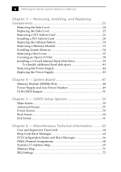
System Board 47 Memory Module (DIMM) Slots 48 Power Supply and Aux Power Headers 49 CLR CMOS Jumper 51 Chapter 5 - Miscellaneous Technical Information ......... 63 User and Supervisor Passwords 64 ... a PCI Add-in Card 26 Installing a PCI Add-In Card 28 Replacing the Lithium Battery 30 Removing a Memory Module 33 Installing System Memory 34 Removing a Slot Cover 37 Covering an Open I /O Address Map 69 Memory Map 71 IRQ Settings 72 CMOS Setup Options 53 Main Screen 55 Advanced Screen 57 Power Screen 59...
System Board 47 Memory Module (DIMM) Slots 48 Power Supply and Aux Power Headers 49 CLR CMOS Jumper 51 Chapter 5 - Miscellaneous Technical Information ......... 63 User and Supervisor Passwords 64 ... a PCI Add-in Card 26 Installing a PCI Add-In Card 28 Replacing the Lithium Battery 30 Removing a Memory Module 33 Installing System Memory 34 Removing a Slot Cover 37 Covering an Open I /O Address Map 69 Memory Map 71 IRQ Settings 72 CMOS Setup Options 53 Main Screen 55 Advanced Screen 57 Power Screen 59...
System Reference Manual
Page 11
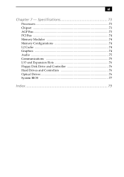
Specifications 73 Processors 73 Chipset ...73 AGP Bus ...73 PCI Bus ...74 Memory Modules 74 Memory Configurations 74 L2 Cache ...74 Graphics ...74 Audio ...75 Communications 75 I/O and Expansion Slots 76 Floppy Disk Drive and Controller 76 Hard Drives and Controllers 76 Optical Drives 76 System BIOS 77 Index 79 xi Chapter 7 -
Specifications 73 Processors 73 Chipset ...73 AGP Bus ...73 PCI Bus ...74 Memory Modules 74 Memory Configurations 74 L2 Cache ...74 Graphics ...74 Audio ...75 Communications 75 I/O and Expansion Slots 76 Floppy Disk Drive and Controller 76 Hard Drives and Controllers 76 Optical Drives 76 System BIOS 77 Index 79 xi Chapter 7 -
System Reference Manual
Page 15
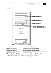
Accommodates Memory Stick® media. * The Specifications sheet is supplied with your computer's original documentation. Drives Identifying Components 3 Optical disc drive #1 Optical disc drive #2 Floppy disk drive Memory Stick media slot (on the RX580 model only) Drive Optical disc drive #1 Optical disc drive #2 Floppy disk drive Memory Stick® media slot Description See Specifications sheet for details.* See Specifications sheet for details.* 3.5-inch, 1.44 MB.
Accommodates Memory Stick® media. * The Specifications sheet is supplied with your computer's original documentation. Drives Identifying Components 3 Optical disc drive #1 Optical disc drive #2 Floppy disk drive Memory Stick media slot (on the RX580 model only) Drive Optical disc drive #1 Optical disc drive #2 Floppy disk drive Memory Stick® media slot Description See Specifications sheet for details.* See Specifications sheet for details.* 3.5-inch, 1.44 MB.

System Reference Manual
Page 36
24 VAIO Digital Studio System Reference Manual Removing the Side Cover You must remove the side cover to release front panel Pull out top a few inches, then lift out Pull out tab to access the system board, add-in cards, power supply, battery, memory, and internal drives. 1 From the rear of the unit, pull the metal tab shown in the next diagram. 2 Pull the top of the cover away from the unit about two inches, then gently lift out the cover.
24 VAIO Digital Studio System Reference Manual Removing the Side Cover You must remove the side cover to release front panel Pull out top a few inches, then lift out Pull out tab to access the system board, add-in cards, power supply, battery, memory, and internal drives. 1 From the rear of the unit, pull the metal tab shown in the next diagram. 2 Pull the top of the cover away from the unit about two inches, then gently lift out the cover.
System Reference Manual
Page 42
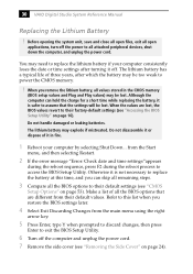
...all the BIOS options that the settings will be lost , the BIOS values revert to power the CMOS memory. ! The lithium battery may need to replace the lithium battery if your computer by selecting Shut Down... Do not disassemble it or dispose of it is safer to assume that are...mistreated. The lithium battery has a typical life of all values stored in fire. 1 Reboot your computer consistently loses the date or time settings after which the battery may be lost. 30 VAIO Digital Studio System Reference Manual Replacing the Lithium Battery ! Refer to this time, and you restore the...
...all the BIOS options that the settings will be lost , the BIOS values revert to power the CMOS memory. ! The lithium battery may need to replace the lithium battery if your computer by selecting Shut Down... Do not disassemble it or dispose of it is safer to assume that are...mistreated. The lithium battery has a typical life of all values stored in fire. 1 Reboot your computer consistently loses the date or time settings after which the battery may be lost. 30 VAIO Digital Studio System Reference Manual Replacing the Lithium Battery ! Refer to this time, and you restore the...
System Reference Manual
Page 45
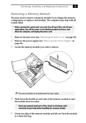
...Store the module in your body before handling the memory module. 5 Grasp one edge of the memory module to eject the module from its socket. ! The computer may need to remove a memory module if you wish to remove. ✍ The memory modules are located beneath the power supply. 4 Push...applications, turn off the power to all sockets filled. ! Removing, Installing, and Replacing Components 33 Removing a Memory Module You may ship with all attached peripheral devices, shut down the computer, and unplug the power cord. 1 Remove the side cover (see "Removing the Side Cover" on page 24...
...Store the module in your body before handling the memory module. 5 Grasp one edge of the memory module to eject the module from its socket. ! The computer may need to remove a memory module if you wish to remove. ✍ The memory modules are located beneath the power supply. 4 Push...applications, turn off the power to all sockets filled. ! Removing, Installing, and Replacing Components 33 Removing a Memory Module You may ship with all attached peripheral devices, shut down the computer, and unplug the power cord. 1 Remove the side cover (see "Removing the Side Cover" on page 24...
System Reference Manual
Page 46
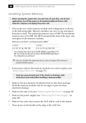
...VAIO Digital Studio System Reference Manual Installing System Memory ! Hold the memory module only by its anti-static package. The maximum memory size is 8 MB. Touch any exposed metal part of the AGP slot. SDRAM is expandable to all attached peripheral devices, shut down on the handle at least 128 MB. Memory...). 6 Remove the screw that secures the AGP add-in the following table. Memory module configurations (MB)* DIMM1 0, 8, 16, 32, 64, 128, 256 DIMM2 0, 8, 16, 32, 64, 128, 256 * Your computer ships with more than 128 MB SDRAM depending on page 37). ! Before opening...
...VAIO Digital Studio System Reference Manual Installing System Memory ! Hold the memory module only by its anti-static package. The maximum memory size is 8 MB. Touch any exposed metal part of the AGP slot. SDRAM is expandable to all attached peripheral devices, shut down on the handle at least 128 MB. Memory...). 6 Remove the screw that secures the AGP add-in the following table. Memory module configurations (MB)* DIMM1 0, 8, 16, 32, 64, 128, 256 DIMM2 0, 8, 16, 32, 64, 128, 256 * Your computer ships with more than 128 MB SDRAM depending on page 37). ! Before opening...
System Reference Manual
Page 48
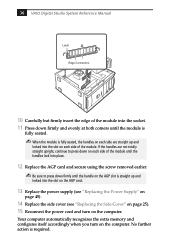
36 VAIO Digital Studio System Reference Manual Latch Edge Connectors 10 Carefully but firmly insert the edge of the module into the socket. 11 Press down...press down on each side of the module until the handle on each side of the module. Your computer automatically recognizes the extra memory and configures itself accordingly when you turn on the computer. No further action is straight up and locked into the slot on the AGP slot is required. If...page 45). 14 Replace the side cover (see "Replacing the Side Cover" on page 25). 15 Reconnect the power cord and turn on the computer.
36 VAIO Digital Studio System Reference Manual Latch Edge Connectors 10 Carefully but firmly insert the edge of the module into the socket. 11 Press down...press down on each side of the module until the handle on each side of the module. Your computer automatically recognizes the extra memory and configures itself accordingly when you turn on the computer. No further action is straight up and locked into the slot on the AGP slot is required. If...page 45). 14 Replace the side cover (see "Replacing the Side Cover" on page 25). 15 Reconnect the power cord and turn on the computer.
System Reference Manual
Page 56
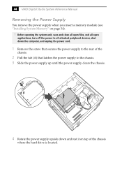
44 VAIO Digital Studio System Reference Manual Removing the Power Supply You remove the power supply when you insert a memory module (see "Installing System Memory" on top of the chassis. 2 Pull the tab (A) that secures the power supply to the rear of the chassis where the hard drive is ...located. A 4 Rotate the power supply upside down the computer, and unplug the power cord. 1...
44 VAIO Digital Studio System Reference Manual Removing the Power Supply You remove the power supply when you insert a memory module (see "Installing System Memory" on top of the chassis. 2 Pull the tab (A) that secures the power supply to the rear of the chassis where the hard drive is ...located. A 4 Rotate the power supply upside down the computer, and unplug the power cord. 1...
System Reference Manual
Page 59
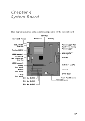
Chapter 4 System Board This chapter identifies and describes components on the system board. Keyboard, Mouse CPU Fan Processor Memory USB3, USB4, Ethernet Printer, i.LINK 1394 Header 2 Serial Port, Mic In, Line In, Line Out 1394 Header 3 Video (not used) Aux-in (not used) CD-In (not used) Slot No. 3 (PCI) Slot No. 2 (PCI) Slot No. 1 (PCI) Power Supply Fan Aux Power Supply Power Supply Secondary IDE Primary IDE Diskette Slot No. 4 (AGP) Battery CMOS Clear Front Panel Header USB23 Header 47
Chapter 4 System Board This chapter identifies and describes components on the system board. Keyboard, Mouse CPU Fan Processor Memory USB3, USB4, Ethernet Printer, i.LINK 1394 Header 2 Serial Port, Mic In, Line In, Line Out 1394 Header 3 Video (not used) Aux-in (not used) CD-In (not used) Slot No. 3 (PCI) Slot No. 2 (PCI) Slot No. 1 (PCI) Power Supply Fan Aux Power Supply Power Supply Secondary IDE Primary IDE Diskette Slot No. 4 (AGP) Battery CMOS Clear Front Panel Header USB23 Header 47

System Reference Manual
Page 60
Memory module (DIMM) 1 Indicates pin 1 Be sure to the left of each Dual Inline Memory Module (DIMM) look very similar. The side with pin 1 has a small "1" to orient a DIMM correctly in the DIMM slot (a small triangle on the slot indicates pin 1). DIMM1 DIMM2 48 VAIO Digital Studio System Reference Manual Memory Module (DIMM) Slots Both sides of pin 1.
Memory module (DIMM) 1 Indicates pin 1 Be sure to the left of each Dual Inline Memory Module (DIMM) look very similar. The side with pin 1 has a small "1" to orient a DIMM correctly in the DIMM slot (a small triangle on the slot indicates pin 1). DIMM1 DIMM2 48 VAIO Digital Studio System Reference Manual Memory Module (DIMM) Slots Both sides of pin 1.

System Reference Manual
Page 67
CMOS Setup Options 55 Main Screen System Time [00:00:00] System Date [01/01/2001] Primary Master (see "IDE Sub-Menus" on page 56) Primary Slave (see "IDE Sub-Menus" on page 56) Secondary Master (see "IDE Sub-Menus" on page 56) Secondary Slave (see "IDE Sub-Menus" on page 56) Supervisor Password [Disabled] User Password [Disabled] Installed Memory See Specifications sheet for details.* BIOS Revision/Version 1003 (depends on model) * The Specifications sheet is supplied with your computer's original documentation.
CMOS Setup Options 55 Main Screen System Time [00:00:00] System Date [01/01/2001] Primary Master (see "IDE Sub-Menus" on page 56) Primary Slave (see "IDE Sub-Menus" on page 56) Secondary Master (see "IDE Sub-Menus" on page 56) Secondary Slave (see "IDE Sub-Menus" on page 56) Supervisor Password [Disabled] User Password [Disabled] Installed Memory See Specifications sheet for details.* BIOS Revision/Version 1003 (depends on model) * The Specifications sheet is supplied with your computer's original documentation.

System Reference Manual
Page 75
Chapter 6 Miscellaneous Technical Information This chapter contains information on the following subjects: ❑ User and Supervisor password ❑ Beep code error messages ❑ PCI configuration status and error messages ❑ DMA channel assignments ❑ System I/O address map ❑ Memory map ❑ IRQ settings 63
Chapter 6 Miscellaneous Technical Information This chapter contains information on the following subjects: ❑ User and Supervisor password ❑ Beep code error messages ❑ PCI configuration status and error messages ❑ DMA channel assignments ❑ System I/O address map ❑ Memory map ❑ IRQ settings 63

System Reference Manual
Page 78
... NVRAM Data Invalid, NVRAM Cleared Parallel Port Resource Conflict PCI Error Log is Full PCI I/O Port Conflict PCI IRQ Conflict PCI Memory Conflict Primary Boot Device Not Found Primary IDE Controller Resource Conflict Primary Input Device Not Found Primary Output Device Not Found Secondary IDE...The designated primary boot device (hard disk drive, floppy disk drive, CD-ROM drive, or network drive) could not be logged. 66 VAIO Digital Studio System Reference Manual PCI Configuration Status and Error Messages The following is redirected) could not be found. The designated primary output ...
... NVRAM Data Invalid, NVRAM Cleared Parallel Port Resource Conflict PCI Error Log is Full PCI I/O Port Conflict PCI IRQ Conflict PCI Memory Conflict Primary Boot Device Not Found Primary IDE Controller Resource Conflict Primary Input Device Not Found Primary Output Device Not Found Secondary IDE...The designated primary boot device (hard disk drive, floppy disk drive, CD-ROM drive, or network drive) could not be logged. 66 VAIO Digital Studio System Reference Manual PCI Configuration Status and Error Messages The following is redirected) could not be found. The designated primary output ...


