
System Reference Manual
Page 12
...internal hard disk drive (all models 46 To set up the new hard drive with the startup disk (PCV-RX490TV model only 49 To identify the additional hard disk space for Giga Pocket use (PCV-RX490TV model only 49 Removing the Power Supply 50 Replacing the Power Supply 51 Chapter 4 - xii... VAIO Digital Studio™ System Reference Manual Chapter 3 - System Board 53 Connectors and Headers 54 Front Panel Header 54 Floppy Disk Drive Header 55 Memory Module (RIMM) Slots 56 PCI Slots 57 AGP Slot 58 IDE Headers 59...
...internal hard disk drive (all models 46 To set up the new hard drive with the startup disk (PCV-RX490TV model only 49 To identify the additional hard disk space for Giga Pocket use (PCV-RX490TV model only 49 Removing the Power Supply 50 Replacing the Power Supply 51 Chapter 4 - xii... VAIO Digital Studio™ System Reference Manual Chapter 3 - System Board 53 Connectors and Headers 54 Front Panel Header 54 Floppy Disk Drive Header 55 Memory Module (RIMM) Slots 56 PCI Slots 57 AGP Slot 58 IDE Headers 59...
System Reference Manual
Page 42
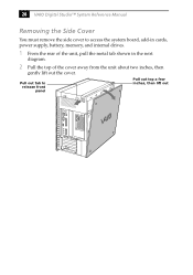
Pull out tab to access the system board, add-in cards, power supply, battery, memory, and internal drives. 1 From the rear of the unit, pull the metal tab shown in the next diagram. 2 Pull the top of the cover away from the unit about two inches, then gently lift out the cover. 28 VAIO Digital Studio™ System Reference Manual Removing the Side Cover You must remove the side cover to release front panel Pull out top a few inches, then lift out
Pull out tab to access the system board, add-in cards, power supply, battery, memory, and internal drives. 1 From the rear of the unit, pull the metal tab shown in the next diagram. 2 Pull the top of the cover away from the unit about two inches, then gently lift out the cover. 28 VAIO Digital Studio™ System Reference Manual Removing the Side Cover You must remove the side cover to release front panel Pull out top a few inches, then lift out
System Reference Manual
Page 48
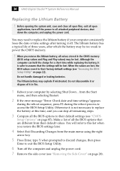
... open applications, turn off . When the values are lost . Do not disassemble it or dispose of it is safer to power the CMOS memory. ! 34 VAIO Digital Studio™ System Reference Manual Replacing the Lithium Battery ! The lithium battery may need to replace the lithium battery if your computer by ...you can hold the charge for a short time while replacing the battery, it off the power to their default values. Otherwise it in the CMOS memory (BIOS setup values and Plug and Play values) may be lost , the BIOS values revert to all values stored in fire. 1 Reboot your computer...
... open applications, turn off . When the values are lost . Do not disassemble it or dispose of it is safer to power the CMOS memory. ! 34 VAIO Digital Studio™ System Reference Manual Replacing the Lithium Battery ! The lithium battery may need to replace the lithium battery if your computer by ...you can hold the charge for a short time while replacing the battery, it off the power to their default values. Otherwise it in the CMOS memory (BIOS setup values and Plug and Play values) may be lost , the BIOS values revert to all values stored in fire. 1 Reboot your computer...

System Reference Manual
Page 51
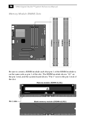
...between sockets. The second slot must be filled with either bank empty. Memory module configurations (MB)* RIMM1 RIMM2 0, 8, 16, 32, 64, 128, 256 0, 8, 16, 32, 64, 128, 256 * All models ship with more than 128 MB of RIMM™ memory if you wish to the chassis. 7 Press down the computer, and...or CRIMM modules. 2 If necessary, remove the memory module you purchased it through the VAIO Direct Web site. ✍ Use only PC-800 Rambus RIMM memory modules. Your model may ship with at the edge of RIMM™ memory. Direct Rambus RIMMS must be upgraded in the following...
...between sockets. The second slot must be filled with either bank empty. Memory module configurations (MB)* RIMM1 RIMM2 0, 8, 16, 32, 64, 128, 256 0, 8, 16, 32, 64, 128, 256 * All models ship with more than 128 MB of RIMM™ memory if you wish to the chassis. 7 Press down the computer, and...or CRIMM modules. 2 If necessary, remove the memory module you purchased it through the VAIO Direct Web site. ✍ Use only PC-800 Rambus RIMM memory modules. Your model may ship with at the edge of RIMM™ memory. Direct Rambus RIMMS must be upgraded in the following...
System Reference Manual
Page 54
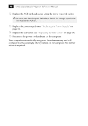
..." on page 29). 15 Reconnect the power cord and turn on the computer. Your computer automatically recognizes the extra memory and will configure itself accordingly when you turn on the computer. 40 VAIO Digital Studio™ System Reference Manual 12 Replace the AGP card and secure using the screw removed earlier. ✍...
..." on page 29). 15 Reconnect the power cord and turn on the computer. Your computer automatically recognizes the extra memory and will configure itself accordingly when you turn on the computer. 40 VAIO Digital Studio™ System Reference Manual 12 Replace the AGP card and secure using the screw removed earlier. ✍...
System Reference Manual
Page 56
42 VAIO Digital Studio™ System Reference Manual 5 Grasp one edge of the memory module and lift out. Empty sockets must be filled with either RIMM or CRIMM modules in a static-free bag. ! Store the module in pairs.
42 VAIO Digital Studio™ System Reference Manual 5 Grasp one edge of the memory module and lift out. Empty sockets must be filled with either RIMM or CRIMM modules in a static-free bag. ! Store the module in pairs.
System Reference Manual
Page 64
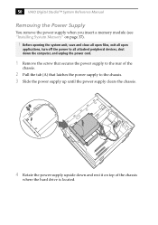
50 VAIO Digital Studio™ System Reference Manual Removing the Power Supply You remove the power supply when you insert a memory module (see "Installing System Memory" on top of the chassis. 2 Pull the tab (A) that latches the power supply to the chassis. 3 Slide the power supply up until the power supply ...
50 VAIO Digital Studio™ System Reference Manual Removing the Power Supply You remove the power supply when you insert a memory module (see "Installing System Memory" on top of the chassis. 2 Pull the tab (A) that latches the power supply to the chassis. 3 Slide the power supply up until the power supply ...
System Reference Manual
Page 70
Memory module (RIMM A1/B1) WARNING HOT A1 A4 A4 A9 6 7 2 Pin 1 side Blank memory module (CRIMM A2/B2) A1 A4 A4 A9 6 7 2 56 VAIO Digital Studio™ System Reference Manual Memory Module (RIMM) Slots RIMMA1 RIMMA2 RIMMB1 RIMMB2 Be sure to the pin 1 end of the slot. The RIMM module shows "A1" on the pin 1 end, and the system board shows "Pin 1" next to orient a RIMM module such that pin 1 of the RIMM module is on the same side as pin 1 of the slot.
Memory module (RIMM A1/B1) WARNING HOT A1 A4 A4 A9 6 7 2 Pin 1 side Blank memory module (CRIMM A2/B2) A1 A4 A4 A9 6 7 2 56 VAIO Digital Studio™ System Reference Manual Memory Module (RIMM) Slots RIMMA1 RIMMA2 RIMMB1 RIMMB2 Be sure to the pin 1 end of the slot. The RIMM module shows "A1" on the pin 1 end, and the system board shows "Pin 1" next to orient a RIMM module such that pin 1 of the RIMM module is on the same side as pin 1 of the slot.
System Reference Manual
Page 112
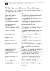
...hard disk drive, floppy disk drive, CD-ROM drive, or network drive) could not be logged. Invalid entry in a conflict. 98 VAIO Digital Studio™ System Reference Manual PCI Configuration Status and Error Messages The following is displayed when more than 15 PCI conflict errors are ...Jumper NVRAM Data Invalid, NVRAM Cleared Parallel Port Resource Conflict PCI Error Log is Full PCI I/O Port Conflict PCI IRQ Conflict PCI Memory Conflict Primary Boot Device Not Found Primary IDE Controller Resource Conflict Primary Input Device Not Found Primary Output Device Not Found Secondary IDE ...
...hard disk drive, floppy disk drive, CD-ROM drive, or network drive) could not be logged. Invalid entry in a conflict. 98 VAIO Digital Studio™ System Reference Manual PCI Configuration Status and Error Messages The following is displayed when more than 15 PCI conflict errors are ...Jumper NVRAM Data Invalid, NVRAM Cleared Parallel Port Resource Conflict PCI Error Log is Full PCI I/O Port Conflict PCI IRQ Conflict PCI Memory Conflict Primary Boot Device Not Found Primary IDE Controller Resource Conflict Primary Input Device Not Found Primary Output Device Not Found Secondary IDE ...
System Reference Manual
Page 114
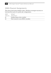
DMA Channel 02 04 Default Assignment Standard floppy disk controller. Direct memory access (DMA) controller. Windows reassigns resources to best meet the needs of a particular configuration. 100 VAIO Digital Studio™ System Reference Manual DMA Channel Assignments This shows the factory default values.
DMA Channel 02 04 Default Assignment Standard floppy disk controller. Direct memory access (DMA) controller. Windows reassigns resources to best meet the needs of a particular configuration. 100 VAIO Digital Studio™ System Reference Manual DMA Channel Assignments This shows the factory default values.

System Reference Manual
Page 124
... modules can vary between sockets. 110 VAIO Digital Studio™ System Reference Manual PCI Bus PCI Level 2.2, 33 MHz zero wait state 3 PCI slots (2 open in the PCV-RX462DS/PCV-RX463DS/PCV-RX465DS/ PCV-RX470DS/PCV-RX480DS models, 1 open in the PCV-RX490TV model) Memory Modules Installed memory Maximum memory Voltage Pins Memory type 128 MB (may ship with at 100 Hz non-interlaced...
... modules can vary between sockets. 110 VAIO Digital Studio™ System Reference Manual PCI Bus PCI Level 2.2, 33 MHz zero wait state 3 PCI slots (2 open in the PCV-RX462DS/PCV-RX463DS/PCV-RX465DS/ PCV-RX470DS/PCV-RX480DS models, 1 open in the PCV-RX490TV model) Memory Modules Installed memory Maximum memory Voltage Pins Memory type 128 MB (may ship with at 100 Hz non-interlaced...

System Reference Manual
Page 132
...specifications 110 lithium battery, replacing 34 lithium ion battery disposal vii safety precautions vii M map - See Also system memory memory configuration specifications 110 memory module connector 56 removing 41 specifications 110 messages error 97 status and error 98 See modem card FCC Part 68 ... and line 16 USB ports 13, 63 I/O slot covering 44 I /O address map and memory map memory - See graphics graphics specifications 110 H hard drive specifications 113 header - 118 VAIO Digital Studio™ System Reference Manual installing additional 3.5 drive 45 DVD-ROM drive performance of 11...
...specifications 110 lithium battery, replacing 34 lithium ion battery disposal vii safety precautions vii M map - See Also system memory memory configuration specifications 110 memory module connector 56 removing 41 specifications 110 messages error 97 status and error 98 See modem card FCC Part 68 ... and line 16 USB ports 13, 63 I/O slot covering 44 I /O address map and memory map memory - See graphics graphics specifications 110 H hard drive specifications 113 header - 118 VAIO Digital Studio™ System Reference Manual installing additional 3.5 drive 45 DVD-ROM drive performance of 11...
System Reference Manual
Page 134
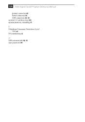
120 VAIO Digital Studio™ System Reference Manual printer connector 65 Serial connector 65 USB connectors 63, 65 system I/O address map 101 system memory, installing 37 T Telephone Consumer Protection Act of 1991 vii TV interference vi U USB connectors 8, 63, 65 user password 96
120 VAIO Digital Studio™ System Reference Manual printer connector 65 Serial connector 65 USB connectors 63, 65 system I/O address map 101 system memory, installing 37 T Telephone Consumer Protection Act of 1991 vii TV interference vi U USB connectors 8, 63, 65 user password 96


