Reference Manual
Page 2
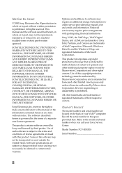
... is prohibited. Notice to the model and serial number when you call your VAIO® computer. All rights reserved. Sony, VAIO, the VAIO logo, VAIO Digital Studio, and i.LINK are trademarks or registered trademarks of such software is prohibited. Use of their respective owners. Model Number: PCV-R553DS Serial Number ii All other rights owners. Software specifications are registered trademarks...
... is prohibited. Notice to the model and serial number when you call your VAIO® computer. All rights reserved. Sony, VAIO, the VAIO logo, VAIO Digital Studio, and i.LINK are trademarks or registered trademarks of such software is prohibited. Use of their respective owners. Model Number: PCV-R553DS Serial Number ii All other rights owners. Software specifications are registered trademarks...

Reference Manual
Page 12
... GAME Connector 64 HEADPHONES, LINE IN, MIC Connectors 65 CD-IN Connector 66 AUX-IN Connector 67 WOL-CON Connector 68 Configuration Jumper 69 xii VAIO Digital Studio™ Reference Manual Chapter 3 - Removing, Installing, and Replacing Components Removing the Cover 22 Removing the Front Panel 24 Replacing the Front Panel 26 Replacing the...
... GAME Connector 64 HEADPHONES, LINE IN, MIC Connectors 65 CD-IN Connector 66 AUX-IN Connector 67 WOL-CON Connector 68 Configuration Jumper 69 xii VAIO Digital Studio™ Reference Manual Chapter 3 - Removing, Installing, and Replacing Components Removing the Cover 22 Removing the Front Panel 24 Replacing the Front Panel 26 Replacing the...

Reference Manual
Page 15
Chapter 1 Identifying Components The following sections identify and describe each component that is visible from the exterior of this manual. 1 Internal components are identified in the appropriate section of the VAIO Digital Studio™ Computer.
Chapter 1 Identifying Components The following sections identify and describe each component that is visible from the exterior of this manual. 1 Internal components are identified in the appropriate section of the VAIO Digital Studio™ Computer.

Reference Manual
Page 18
Automatically opens and closes the optical drive tray. 4 VAIO Digital Studio™ Reference Manual Buttons and Switches Optical disc eject Diskette eject Power/Standby FRNTPNLB.VSD Button or switch Power/Standby switch Diskette eject button Optical disc eject button Description Turns system power on, off, or into standby mode. Ejects a diskette.
Automatically opens and closes the optical drive tray. 4 VAIO Digital Studio™ Reference Manual Buttons and Switches Optical disc eject Diskette eject Power/Standby FRNTPNLB.VSD Button or switch Power/Standby switch Diskette eject button Optical disc eject button Description Turns system power on, off, or into standby mode. Ejects a diskette.

Reference Manual
Page 20
6 VAIO Digital Studio™ Reference Manual Connectors USB i.LINK FRNTPNLD.VSD Connector i.LINK® (IEEE-1394)* USB Description Connects to the device. A 4-pin i.LINK connector cannot supply power to a digital device that has a 4-pin i.LINK connector. Connects to USB devices. * To connect to the device if the device also has a 6-pin i.LINK connector. A 6-pin i.LINK connector can supply power from the computer to a 6-pin i.LINK device, use the i.LINK connector on the back of the system.
6 VAIO Digital Studio™ Reference Manual Connectors USB i.LINK FRNTPNLD.VSD Connector i.LINK® (IEEE-1394)* USB Description Connects to the device. A 4-pin i.LINK connector cannot supply power to a digital device that has a 4-pin i.LINK connector. Connects to USB devices. * To connect to the device if the device also has a 6-pin i.LINK connector. A 6-pin i.LINK connector can supply power from the computer to a 6-pin i.LINK device, use the i.LINK connector on the back of the system.

Reference Manual
Page 22
8 VAIO Digital Studio™ Reference Manual Icons Icon labels Icon OM04692X.VSD Description MOUSE connector KEYBOARD connector USB (Universal Serial Bus) connector SERIAL connector PRINTER connector GAME/MIDI connector HEADPHONES connector LINE IN jack (audio) MIC (microphone) jack MONITOR connector Ethernet connector
8 VAIO Digital Studio™ Reference Manual Icons Icon labels Icon OM04692X.VSD Description MOUSE connector KEYBOARD connector USB (Universal Serial Bus) connector SERIAL connector PRINTER connector GAME/MIDI connector HEADPHONES connector LINE IN jack (audio) MIC (microphone) jack MONITOR connector Ethernet connector

Reference Manual
Page 24
.... SERIAL Connector The SERIAL connector is located at the front and rear of the system. They are physically identical and have the same pinout. 10 VAIO Digital Studio™ Reference Manual I/O Connectors The following section identifies the various I/O connectors. A USB connector is a standard 9-pin DB-9 male connector. KY0003.VS 1 6 9 5 KY0057.VSD KEYBOARD MOUSE...
.... SERIAL Connector The SERIAL connector is located at the front and rear of the system. They are physically identical and have the same pinout. 10 VAIO Digital Studio™ Reference Manual I/O Connectors The following section identifies the various I/O connectors. A USB connector is a standard 9-pin DB-9 male connector. KY0003.VS 1 6 9 5 KY0057.VSD KEYBOARD MOUSE...

Reference Manual
Page 26
The GAME connector is a standard 15-pin DB-15 female connector. Electret condenser microphone input. 1.0 Vrms (typical), 10 Kohm impedance. HEADPHONES LINE IN MIC Connector HEADPHONES MIC LINE IN Description 1.0 Vrms (typical). KY0013.VSD They are physically identical, but have different connections. 12 VAIO Digital Studio™ Reference Manual GAME Connector The GAME connector is also used to connect MIDI devices. 8 15 9 1 KY0012.VSD MIC, LINE IN, and HEADPHONES The MIC, LINE IN, and HEADPHONES jacks are standard 3.5 mm stereo minijacks.
The GAME connector is a standard 15-pin DB-15 female connector. Electret condenser microphone input. 1.0 Vrms (typical), 10 Kohm impedance. HEADPHONES LINE IN MIC Connector HEADPHONES MIC LINE IN Description 1.0 Vrms (typical). KY0013.VSD They are physically identical, but have different connections. 12 VAIO Digital Studio™ Reference Manual GAME Connector The GAME connector is also used to connect MIDI devices. 8 15 9 1 KY0012.VSD MIC, LINE IN, and HEADPHONES The MIC, LINE IN, and HEADPHONES jacks are standard 3.5 mm stereo minijacks.

Reference Manual
Page 28
14 VAIO Digital Studio™ Reference Manual Ethernet Connector The Ethernet connector on the rear of which is used to connect to a 100Base-TX/10Base-T Ethernet network. PCI #4 PCI #3 PCI #2 PCI #1 OM04577B.VSD Ethernet On back of system KY0100.VSD Expansion Slots There are occupied by the fax/modem card (PCI #1), i.LINK card (PCI #2), and D-Link card (PC #3). The other three PCI slots are four PCI slots, one of the system is available for expansion (PCI #4).
14 VAIO Digital Studio™ Reference Manual Ethernet Connector The Ethernet connector on the rear of which is used to connect to a 100Base-TX/10Base-T Ethernet network. PCI #4 PCI #3 PCI #2 PCI #1 OM04577B.VSD Ethernet On back of system KY0100.VSD Expansion Slots There are occupied by the fax/modem card (PCI #1), i.LINK card (PCI #2), and D-Link card (PC #3). The other three PCI slots are four PCI slots, one of the system is available for expansion (PCI #4).
Reference Manual
Page 30
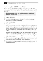
... item has a triangle ( ) to select a menu from any open files and exit the Microsoft® Windows® operating system. 1 Reboot the system. 2 When the Sony logo appears, press F3. 16 VAIO Digital Studio™ Reference Manual Accessing the BIOS Setup Utility You must access the BIOS Setup Utility to make changes to modify a setting.
... item has a triangle ( ) to select a menu from any open files and exit the Microsoft® Windows® operating system. 1 Reboot the system. 2 When the Sony logo appears, press F3. 16 VAIO Digital Studio™ Reference Manual Accessing the BIOS Setup Utility You must access the BIOS Setup Utility to make changes to modify a setting.

Reference Manual
Page 32
...period of inactivity (in minutes) that you use your computer. 18 VAIO Digital Studio™ Reference Manual 5 Select the power scheme that is most appropriate for System standby, Turn off monitor, and Turn off hard disks option allows you to elapse before your computer goes on AC power. To change a power scheme..., change the settings for the way you want to elapse before your monitor turns off when your computer is reactivated when you want to specify the period of inactivity (in minutes) that you click the left mouse button or press a key...
...period of inactivity (in minutes) that you use your computer. 18 VAIO Digital Studio™ Reference Manual 5 Select the power scheme that is most appropriate for System standby, Turn off monitor, and Turn off hard disks option allows you to elapse before your computer goes on AC power. To change a power scheme..., change the settings for the way you want to elapse before your monitor turns off when your computer is reactivated when you want to specify the period of inactivity (in minutes) that you click the left mouse button or press a key...

Reference Manual
Page 36
The screws are located at the top center, and the lower left to right. KY0064B.VSD 3 Remove the three screws from left and right corners. 22 VAIO Digital Studio™ Reference Manual Removing the Cover You must remove the cover to access the system board, add-in cards, power supply, battery, memory, and internal drives. 1 From the rear of the unit, press the two tabs on the right side. 2 Remove the frame from the unit by gently pulling it from the metal back plate.
The screws are located at the top center, and the lower left to right. KY0064B.VSD 3 Remove the three screws from left and right corners. 22 VAIO Digital Studio™ Reference Manual Removing the Cover You must remove the cover to access the system board, add-in cards, power supply, battery, memory, and internal drives. 1 From the rear of the unit, press the two tabs on the right side. 2 Remove the frame from the unit by gently pulling it from the metal back plate.

Reference Manual
Page 38
24 VAIO Digital Studio™ Reference Manual Removing the Front Panel You must remove the front panel to the unit, press the power-on button on the front, then ...
24 VAIO Digital Studio™ Reference Manual Removing the Front Panel You must remove the front panel to the unit, press the power-on button on the front, then ...

Reference Manual
Page 40
26 VAIO Digital Studio™ Reference Manual Replacing the Front Panel 1 Insert the two flat plastic tabs (located on the bottom of the front panel) into the slots at ...
26 VAIO Digital Studio™ Reference Manual Replacing the Front Panel 1 Insert the two flat plastic tabs (located on the bottom of the front panel) into the slots at ...

Reference Manual
Page 42
KY0068.VSD 28 VAIO Digital Studio™ Reference Manual 5 Gently press the frame in until it clicks into position.
KY0068.VSD 28 VAIO Digital Studio™ Reference Manual 5 Gently press the frame in until it clicks into position.
Reference Manual
Page 44
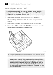
... card. Hold the add-in card by its edges and do not touch any static electricity in an anti-static wrapper for future use. 30 VAIO Digital Studio™ Reference Manual Removing an Add-in your body. As a precaution, touch any exposed metal part on the metal chassis (preferably the metal part...card to side. ! Before opening the system unit, save any open files, exit the Windows® operating system, turn off the power of the computer and all attached peripherals, and then unplug the power cord. 1 Remove the cover (see "Removing the Cover" on the card. Static electricity in Card...
... card. Hold the add-in card by its edges and do not touch any static electricity in an anti-static wrapper for future use. 30 VAIO Digital Studio™ Reference Manual Removing an Add-in your body. As a precaution, touch any exposed metal part on the metal chassis (preferably the metal part...card to side. ! Before opening the system unit, save any open files, exit the Windows® operating system, turn off the power of the computer and all attached peripherals, and then unplug the power cord. 1 Remove the cover (see "Removing the Cover" on the card. Static electricity in Card...

Reference Manual
Page 46
...hold the charge for a short time while replacing the battery, it is safer to replace the lithium battery if your computer by selecting Shut Down... 32 VAIO Digital Studio™ Reference Manual Replacing the Lithium Battery You may explode if mistreated. The lithium battery may need to assume that ... Setup Utility. When you restore the BIOS settings later. 4 Select Exit Discarding Changes from the Start menu, and then selecting Restart the computer. 2 If the error message "Error: Check date and time settings"appears during the reboot sequence, press F2 during the reboot process to...
...hold the charge for a short time while replacing the battery, it is safer to replace the lithium battery if your computer by selecting Shut Down... 32 VAIO Digital Studio™ Reference Manual Replacing the Lithium Battery You may explode if mistreated. The lithium battery may need to assume that ... Setup Utility. When you restore the BIOS settings later. 4 Select Exit Discarding Changes from the Start menu, and then selecting Restart the computer. 2 If the error message "Error: Check date and time settings"appears during the reboot sequence, press F2 during the reboot process to...

Reference Manual
Page 48
... settings were retained during the reboot process to exit the BIOS Setup Utility. 34 VAIO Digital Studio™ Reference Manual 17 If the error message "Error: Check date and time settings." The computer's BIOS settings are now restored. appears during the reboot sequence, press F2 during the battery replacement and you can skip the...
... settings were retained during the reboot process to exit the BIOS Setup Utility. 34 VAIO Digital Studio™ Reference Manual 17 If the error message "Error: Check date and time settings." The computer's BIOS settings are now restored. appears during the reboot sequence, press F2 during the battery replacement and you can skip the...

Reference Manual
Page 50
... fully seated. ✍ When the module is fully seated, the handles on each side of pin 1 on the module and pin 1 on page 27). 36 VAIO Digital Studio™ Reference Manual 7 Align the module over the appropriate socket, noting the location of the module.
... fully seated. ✍ When the module is fully seated, the handles on each side of pin 1 on the module and pin 1 on page 27). 36 VAIO Digital Studio™ Reference Manual 7 Align the module over the appropriate socket, noting the location of the module.
Reference Manual
Page 52
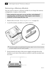
38 VAIO Digital Studio™ Reference Manual Removing a Memory Module You may need to remove a memory module if you wish to remove. KY0073.VSD ✍ The memory modules are ... memory module to reach the memory modules. 3 Reach around each side of the power supply and push down the handle on each side of the computer and all attached peripherals, and then unplug the power cord. 1 Remove the cover (see "Removing the Cover" on page 22). 2 Locate the memory module you...
38 VAIO Digital Studio™ Reference Manual Removing a Memory Module You may need to remove a memory module if you wish to remove. KY0073.VSD ✍ The memory modules are ... memory module to reach the memory modules. 3 Reach around each side of the power supply and push down the handle on each side of the computer and all attached peripherals, and then unplug the power cord. 1 Remove the cover (see "Removing the Cover" on page 22). 2 Locate the memory module you...


