

Reference Manual
Page 2
... Inc. Updates and additions to the model and serial number when you call your VAIO® computer. Owner's Record The model number and serial number are trademarks of your Sony Service Center. BE LIABLE FOR ANY INCIDENTAL, CONSEQUENTIAL, OR SPECIAL DAMAGES, WHETHER BASED ON TORT, CONTRACT, OR OTHERWISE, ARISING OUT OF OR IN... are trademarks or registered trademarks of such software is governed by third parties. Subscriptions to current retail versions. i.LINK is prohibited. All other . Model Number: PCV-J120 Serial Number ii
... Inc. Updates and additions to the model and serial number when you call your VAIO® computer. Owner's Record The model number and serial number are trademarks of your Sony Service Center. BE LIABLE FOR ANY INCIDENTAL, CONSEQUENTIAL, OR SPECIAL DAMAGES, WHETHER BASED ON TORT, CONTRACT, OR OTHERWISE, ARISING OUT OF OR IN... are trademarks or registered trademarks of such software is governed by third parties. Subscriptions to current retail versions. i.LINK is prohibited. All other . Model Number: PCV-J120 Serial Number ii

Reference Manual
Page 12
... GAME Connector 57 HEADPHONES, LINE IN, MIC Connectors 58 CD-IN Connector 59 AUX-IN Connector 60 WOL Connector 61 Configuration Jumper 62 Chapter 5 - xii VAIO® Reference Manual Chapter 3 - i.LINK® Card Chapter 7 - Fax/Modem Card Chapter 6 - Ethernet Card
... GAME Connector 57 HEADPHONES, LINE IN, MIC Connectors 58 CD-IN Connector 59 AUX-IN Connector 60 WOL Connector 61 Configuration Jumper 62 Chapter 5 - xii VAIO® Reference Manual Chapter 3 - i.LINK® Card Chapter 7 - Fax/Modem Card Chapter 6 - Ethernet Card

Reference Manual
Page 15
Chapter 1 Identifying Components The following sections identify and describe each component that is visible from the exterior of this manual. 1 Internal components are identified in the appropriate section of the VAIO® Computer.
Chapter 1 Identifying Components The following sections identify and describe each component that is visible from the exterior of this manual. 1 Internal components are identified in the appropriate section of the VAIO® Computer.

Reference Manual
Page 18
Automatically opens and closes the CD-RW drive tray. Ejects a diskette. 4 VAIO® Reference Manual Buttons and Switches Eject hole CD-RW disc eject Diskette eject Power/Standby FRNTPNLB.VSD Button or switch Power/Standby switch Diskette eject button CD-RW disc eject button Description Turns system power on, off, or into standby mode.
Automatically opens and closes the CD-RW drive tray. Ejects a diskette. 4 VAIO® Reference Manual Buttons and Switches Eject hole CD-RW disc eject Diskette eject Power/Standby FRNTPNLB.VSD Button or switch Power/Standby switch Diskette eject button CD-RW disc eject button Description Turns system power on, off, or into standby mode.

Reference Manual
Page 22
Do not plug a phone into this connector.) 8 VAIO® Reference Manual Icon Description TELEPHONE (for phone) i.LINK® (IEEE1394) interface Ethernet connector (10Base-T/100Base-TX) (This connector is for LAN use only.
Do not plug a phone into this connector.) 8 VAIO® Reference Manual Icon Description TELEPHONE (for phone) i.LINK® (IEEE1394) interface Ethernet connector (10Base-T/100Base-TX) (This connector is for LAN use only.

Reference Manual
Page 24
10 VAIO® Reference Manual PRINTER Connector The PRINTER connector is a standard 25-pin DB-25 female connector. 13 25 14 1 KY0005.VSD MONITOR The MONITOR connector is a standard 15-pin female high-density VGAtype connector. 10 15 5 11 1 6 KY0004.VSD
10 VAIO® Reference Manual PRINTER Connector The PRINTER connector is a standard 25-pin DB-25 female connector. 13 25 14 1 KY0005.VSD MONITOR The MONITOR connector is a standard 15-pin female high-density VGAtype connector. 10 15 5 11 1 6 KY0004.VSD

Reference Manual
Page 26
... Connector The Ethernet connector is a standard RJ-45 modular jack that comes from the wall, and the TELEPHONE jack is for connecting the computer to a 10Base-T/100Base-TX Ethernet LAN connection. They are physically identical and have identical connections. i.LINK® (IEEE1394) Connectors The 6-pin...cord into the LINE jack, will not work correctly. However, the modem will not damage the modem card or telephone equipment. 12 VAIO® Reference Manual TELEPHONE and LINE The TELEPHONE and LINE jacks are standard RJ-11 female phone jacks. This connector is for LAN...
... Connector The Ethernet connector is a standard RJ-45 modular jack that comes from the wall, and the TELEPHONE jack is for connecting the computer to a 10Base-T/100Base-TX Ethernet LAN connection. They are physically identical and have identical connections. i.LINK® (IEEE1394) Connectors The 6-pin...cord into the LINE jack, will not work correctly. However, the modem will not damage the modem card or telephone equipment. 12 VAIO® Reference Manual TELEPHONE and LINE The TELEPHONE and LINE jacks are standard RJ-11 female phone jacks. This connector is for LAN...

Reference Manual
Page 30
... "CMOS Setup Options" on page 69 for information on BIOS settings). ! Before rebooting the system, save any top-level screen and follow the prompts. 16 VAIO® Reference Manual Accessing the BIOS Setup Utility You must access the BIOS Setup Utility to make changes to select items within a menu. The following... an option, press ESC to select a menu from any open files and exit the Microsoft® Windows® operating system. 1 Reboot the system. 2 When the Sony logo appears, press F3.
... "CMOS Setup Options" on page 69 for information on BIOS settings). ! Before rebooting the system, save any top-level screen and follow the prompts. 16 VAIO® Reference Manual Accessing the BIOS Setup Utility You must access the BIOS Setup Utility to make changes to select items within a menu. The following... an option, press ESC to select a menu from any open files and exit the Microsoft® Windows® operating system. 1 Reboot the system. 2 When the Sony logo appears, press F3.

Reference Manual
Page 32
... specify the period of inactivity (in minutes) before your computer goes in the hibernate state. Power is running on AC power. 18 VAIO® Reference Manual inactivity (in minutes) that you want to elapse before your hard disks turn off when your computer is reactivated when you click the left mouse button or..., click Save As, type a descriptive name, and then click OK. 5 Click the Advanced tab. 6 Select the desired settings. Power is running on standby when your computer is reactivated when you want to elapse before your...
... specify the period of inactivity (in minutes) before your computer goes in the hibernate state. Power is running on AC power. 18 VAIO® Reference Manual inactivity (in minutes) that you want to elapse before your hard disks turn off when your computer is reactivated when you click the left mouse button or..., click Save As, type a descriptive name, and then click OK. 5 Click the Advanced tab. 6 Select the desired settings. Power is running on standby when your computer is reactivated when you want to elapse before your...

Reference Manual
Page 36
KY0064B.VSD 22 VAIO® Reference Manual Removing the Side Panel You must remove the side panel to access the system board, add-in cards, power supply, battery, memory, and internal drives. 1 From the rear of the unit, remove the single screw on the right side. 2 Slide back the panel about ½ inch, then lift out.
KY0064B.VSD 22 VAIO® Reference Manual Removing the Side Panel You must remove the side panel to access the system board, add-in cards, power supply, battery, memory, and internal drives. 1 From the rear of the unit, remove the single screw on the right side. 2 Slide back the panel about ½ inch, then lift out.

Reference Manual
Page 38
Front panel 1 KY0093.VSD 24 VAIO® Reference Manual Replacing the Front Panel 1 Insert the two flat plastic tabs (located on the top of the front panel) into the slots at the top of the chassis. 2 Push the bottom of the front panel in until the tabs snap into place..
Front panel 1 KY0093.VSD 24 VAIO® Reference Manual Replacing the Front Panel 1 Insert the two flat plastic tabs (located on the top of the front panel) into the slots at the top of the chassis. 2 Push the bottom of the front panel in until the tabs snap into place..

Reference Manual
Page 40
... VAIO® Reference Manual Installing an Add-In Card ! KY0070.VSD 5 Replace the screw that secures the card. 6 Attach any instructions that the bottom of the bracket fits into the PCI slot connector. Ensure that came with the add-in card). 7 Replace the cover (see "Removing a Slot Cover" on the computer... chassis lip after the card is fully inserted. Before opening the system unit, save any open files, exit Windows, turn off the power of the computer and all attached peripherals, and then unplug the power cord. 1 Remove the cover (see "Removing the Side Panel" on page 22). 2 Locate ...
... VAIO® Reference Manual Installing an Add-In Card ! KY0070.VSD 5 Replace the screw that secures the card. 6 Attach any instructions that the bottom of the bracket fits into the PCI slot connector. Ensure that came with the add-in card). 7 Replace the cover (see "Removing a Slot Cover" on the computer... chassis lip after the card is fully inserted. Before opening the system unit, save any open files, exit Windows, turn off the power of the computer and all attached peripherals, and then unplug the power cord. 1 Remove the cover (see "Removing the Side Panel" on page 22). 2 Locate ...

Reference Manual
Page 42
28 VAIO® Reference Manual 5 If you do not replace the card or install another add-in card, install a slot cover over the vacant slot at the rear of the chassis (see "Covering an Open I/O Slot" on page 39). 6 Replace the cover (see "Replacing the Side Panel" on page 25).
28 VAIO® Reference Manual 5 If you do not replace the card or install another add-in card, install a slot cover over the vacant slot at the rear of the chassis (see "Covering an Open I/O Slot" on page 39). 6 Replace the cover (see "Replacing the Side Panel" on page 25).

Reference Manual
Page 44
... new battery into the battery holder, with the plus (+) side up, and gently press down until the battery snaps into place. ✍ The Sony CR2032 battery is recommended. 30 VAIO® Reference Manual 8 If necessary, remove any cables that were disconnected. 14 Replace the side panel (see "Removing an Add-in Card... were removed. 13 Reconnect any add-in cards (see "Replacing the Side Panel" on page 25). 15 Reconnect the power cord and turn on the computer.
... new battery into the battery holder, with the plus (+) side up, and gently press down until the battery snaps into place. ✍ The Sony CR2032 battery is recommended. 30 VAIO® Reference Manual 8 If necessary, remove any cables that were disconnected. 14 Replace the side panel (see "Removing an Add-in Card... were removed. 13 Reconnect any add-in cards (see "Replacing the Side Panel" on page 25). 15 Reconnect the power cord and turn on the computer.
Reference Manual
Page 46
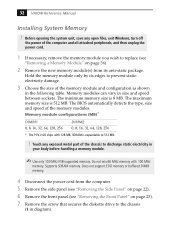
...Memory modules can vary in diagram). The BIOS automatically detects the type, size and speed of the computer and all attached peripherals, and then unplug the power cord. 1 If necessary, remove the memory ... 0, 8, 16, 32, 64, 128, 256 DIMM2 0, 8, 16, 32, 64, 128, 256 * The PCV-J120 ships with 100 MHz memory. Do not mix 66 MHz memory with 128 MB. Does not support EDO memory or ... damage. 3 Choose the size of the chassis to 512 MB. ! Supports SDRAM memory. 32 VAIO® Reference Manual Installing System Memory ! The minimum memory size is 512 MB. Before opening the...
...Memory modules can vary in diagram). The BIOS automatically detects the type, size and speed of the computer and all attached peripherals, and then unplug the power cord. 1 If necessary, remove the memory ... 0, 8, 16, 32, 64, 128, 256 DIMM2 0, 8, 16, 32, 64, 128, 256 * The PCV-J120 ships with 100 MHz memory. Do not mix 66 MHz memory with 128 MB. Does not support EDO memory or ... damage. 3 Choose the size of the chassis to 512 MB. ! Supports SDRAM memory. 32 VAIO® Reference Manual Installing System Memory ! The minimum memory size is 512 MB. Before opening the...

Reference Manual
Page 48
34 VAIO® Reference Manual 9 Align the memory module over the appropriate socket, noting the location of the module until the handles lock into place. If the ...
34 VAIO® Reference Manual 9 Align the memory module over the appropriate socket, noting the location of the module until the handles lock into place. If the ...

Reference Manual
Page 50
... VAIO® Reference Manual Removing a Memory Module You may need to the chassis and slide the diskette drive out about two inches (the attached cables limit this distance). 1 VOY001.VSD Before opening the system unit, save any open files, exit the Windows® operating system, turn off the power of the computer...
... VAIO® Reference Manual Removing a Memory Module You may need to the chassis and slide the diskette drive out about two inches (the attached cables limit this distance). 1 VOY001.VSD Before opening the system unit, save any open files, exit the Windows® operating system, turn off the power of the computer...

Reference Manual
Page 52
38 VAIO® Reference Manual Removing a Slot Cover You remove a slot cover when you install an add-in card that occupies a previously-empty slot. 1 Disconnect the power cord from the computer. 2 Lay the system on its side. 3 Remove the side panel (see "Removing the Side Panel" on page 22). 4 Locate the slot whose cover you want to remove. 5 Remove the screw from the slot cover. 6 Remove the loose slot cover and retain it for future use. KY0069.VSD
38 VAIO® Reference Manual Removing a Slot Cover You remove a slot cover when you install an add-in card that occupies a previously-empty slot. 1 Disconnect the power cord from the computer. 2 Lay the system on its side. 3 Remove the side panel (see "Removing the Side Panel" on page 22). 4 Locate the slot whose cover you want to remove. 5 Remove the screw from the slot cover. 6 Remove the loose slot cover and retain it for future use. KY0069.VSD

Reference Manual
Page 54
... blinks when either internal drive is active. ! Before opening the system unit, save any open files, exit Windows, turn off the power of the computer and all attached peripherals, and then unplug the power cord. 1 Configure the jumpers on the new drive as a slave device (see "Removing the... Side Panel" on page 22). 4 Lift the tab adjacent to hold an additional 3½" IDE hard disk drive. 40 VAIO® Reference Manual Installing a 3½" Internal Hard Disk Drive Your system comes with an available bay to the drive holder. Power connector Jumpers Drive connector...
... blinks when either internal drive is active. ! Before opening the system unit, save any open files, exit Windows, turn off the power of the computer and all attached peripherals, and then unplug the power cord. 1 Configure the jumpers on the new drive as a slave device (see "Removing the... Side Panel" on page 22). 4 Lift the tab adjacent to hold an additional 3½" IDE hard disk drive. 40 VAIO® Reference Manual Installing a 3½" Internal Hard Disk Drive Your system comes with an available bay to the drive holder. Power connector Jumpers Drive connector...

Reference Manual
Page 56
42 VAIO® Reference Manual 7 Slide the new drive into the drive holder and align the holes on each side of the drive holder (screws are provided with the new drive). Align holes KY0083.VSD 8 Secure the drive to the drive holder using the two holes on each side of the drive holder. KY0085.VSD Second power connector Second drive connector 11 Make sure the drive connector is connected securely to the new drive. Do not overtighten the screws. 9 Connect the second drive connector to the new drive (see next diagram). 10 Connect the second power connector to the motherboard.
42 VAIO® Reference Manual 7 Slide the new drive into the drive holder and align the holes on each side of the drive holder (screws are provided with the new drive). Align holes KY0083.VSD 8 Secure the drive to the drive holder using the two holes on each side of the drive holder. KY0085.VSD Second power connector Second drive connector 11 Make sure the drive connector is connected securely to the new drive. Do not overtighten the screws. 9 Connect the second drive connector to the new drive (see next diagram). 10 Connect the second power connector to the motherboard.


