
Reference Manual
Page 11
... 1991 (United States) ..... Identifying Components Front View 2 Drives 3 Buttons and Switches 4 Indicators 5 Rear View ...6 Icons ...7 I/O Connectors 9 Expansion Slots 13 Chapter 2 - Configuring Your System Accessing the BIOS Setup Utility 16 Changing the Display's Power Management Settings 17 Configuring the System Board 19 xi
... 1991 (United States) ..... Identifying Components Front View 2 Drives 3 Buttons and Switches 4 Indicators 5 Rear View ...6 Icons ...7 I/O Connectors 9 Expansion Slots 13 Chapter 2 - Configuring Your System Accessing the BIOS Setup Utility 16 Changing the Display's Power Management Settings 17 Configuring the System Board 19 xi
Reference Manual
Page 13
... Code Error Messages 85 PCI Configuration Status and Error Messages 86 DMA Channel Assignments 87 System I /O and Expansion Slots 95 Drives and Controllers 96 System BIOS 96 Specifications Processor 93 Chipset ...93 PCI Bus ...93 Memory Modules (DIMMs 93 DIMM Configurations 94 L2 Cache ...94 Graphics ...94 Audio ...95 Communications 95...
... Code Error Messages 85 PCI Configuration Status and Error Messages 86 DMA Channel Assignments 87 System I /O and Expansion Slots 95 Drives and Controllers 96 System BIOS 96 Specifications Processor 93 Chipset ...93 PCI Bus ...93 Memory Modules (DIMMs 93 DIMM Configurations 94 L2 Cache ...94 Graphics ...94 Audio ...95 Communications 95...
Reference Manual
Page 29
Chapter 2 Configuring Your System This chapter contains information on configuring your system can consist of the following: ❑ Making changes to the BIOS settings ❑ Making changes to the display's power management settings ❑ Changing the system board jumper position 15 Configuring your system.
Chapter 2 Configuring Your System This chapter contains information on configuring your system can consist of the following: ❑ Making changes to the BIOS settings ❑ Making changes to the display's power management settings ❑ Changing the system board jumper position 15 Configuring your system.
Reference Manual
Page 30
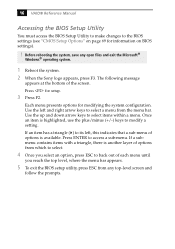
...until you reach the top level, where the menu bar appears. 5 To exit the BIOS setup utility, press ESC from the menu bar. 16 VAIO® Reference Manual Accessing the BIOS Setup Utility You must access the BIOS Setup Utility to make changes to select items within a menu. Use the up and down..., press ESC to select a menu from any open files and exit the Microsoft® Windows® operating system. 1 Reboot the system. 2 When the Sony logo appears, press F3. Before rebooting the system, save any top-level screen and follow the prompts. The following message appears at the bottom of...
...until you reach the top level, where the menu bar appears. 5 To exit the BIOS setup utility, press ESC from the menu bar. 16 VAIO® Reference Manual Accessing the BIOS Setup Utility You must access the BIOS Setup Utility to make changes to select items within a menu. Use the up and down..., press ESC to select a menu from any open files and exit the Microsoft® Windows® operating system. 1 Reboot the system. 2 When the Sony logo appears, press F3. Before rebooting the system, save any top-level screen and follow the prompts. The following message appears at the bottom of...
Reference Manual
Page 43
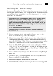
... 6 Turn off . Otherwise it is safer to assume that are lost . When you restore the BIOS settings later. 4 Select Exit Discarding Changes from the Start menu, and then selecting Restart the computer. 2 If the error message "Error: Check date and time settings"appears during the reboot sequence, ...press F2 during the reboot process to access the BIOS Setup Utility. Although the computer can skip all remaining steps. 3 Compare all the BIOS options that the settings will refer to this time, and you can hold the charge for a short...
... 6 Turn off . Otherwise it is safer to assume that are lost . When you restore the BIOS settings later. 4 Select Exit Discarding Changes from the Start menu, and then selecting Restart the computer. 2 If the error message "Error: Check date and time settings"appears during the reboot sequence, ...press F2 during the reboot process to access the BIOS Setup Utility. Although the computer can skip all remaining steps. 3 Compare all the BIOS options that the settings will refer to this time, and you can hold the charge for a short...
Reference Manual
Page 45
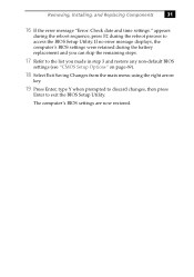
... are now restored. If no error message displays, the computer's BIOS settings were retained during the reboot process to exit the BIOS Setup Utility. Removing, Installing, and Replacing Components 31 16 If the error message "Error: Check date and time settings." appears during the reboot sequence, press ... during the battery replacement and you can skip the remaining steps. 17 Refer to the list you made in step 3 and restore any non-default BIOS settings (see "CMOS Setup Options" on page 69). 18 Select Exit Saving Changes from the main menu using the right arrow key. 19 Press Enter...
... are now restored. If no error message displays, the computer's BIOS settings were retained during the reboot process to exit the BIOS Setup Utility. Removing, Installing, and Replacing Components 31 16 If the error message "Error: Check date and time settings." appears during the reboot sequence, press ... during the battery replacement and you can skip the remaining steps. 17 Refer to the list you made in step 3 and restore any non-default BIOS settings (see "CMOS Setup Options" on page 69). 18 Select Exit Saving Changes from the main menu using the right arrow key. 19 Press Enter...
Reference Manual
Page 46
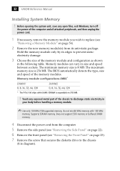
... size and speed between sockets. The minimum memory size is 256 MB. 32 VAIO® Reference Manual Installing System Memory ! Before opening the system unit, save ..., remove the memory module you wish to 256 MB. ! The BIOS automatically detects the type, size and speed of the memory module and...MB. Does not support EDO memory or buffered DIMM memory. 4 Disconnect the power cord from the computer. 5 Remove the side panel (see "Removing the Side Panel" on page 22). 6 Remove ... DIMM2 0, 8, 16, 32, 64, 128 * The PCV-J100 ships with 100 MHz memory. Supports SDRAM memory.
... size and speed between sockets. The minimum memory size is 256 MB. 32 VAIO® Reference Manual Installing System Memory ! Before opening the system unit, save ..., remove the memory module you wish to 256 MB. ! The BIOS automatically detects the type, size and speed of the memory module and...MB. Does not support EDO memory or buffered DIMM memory. 4 Disconnect the power cord from the computer. 5 Remove the side panel (see "Removing the Side Panel" on page 22). 6 Remove ... DIMM2 0, 8, 16, 32, 64, 128 * The PCV-J100 ships with 100 MHz memory. Supports SDRAM memory.
Reference Manual
Page 83
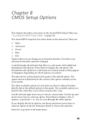
...that there is not enclosed in brackets cannot be changed. The other options. If you select). The available options are enclosed in brackets. The Award BIOS setup has five menu items on which options you display the list of options, or press the + or - A small triangle ( ) indicates that... item shown in [brackets] in this guide. Chapter 8 CMOS Setup Options This chapter describes each screen in the Award BIOS Setup Utility (see "Accessing the BIOS Setup Utility" on the screen is the option currently set for each item are shown without brackets directly below the default ...
...that there is not enclosed in brackets cannot be changed. The other options. If you select). The available options are enclosed in brackets. The Award BIOS setup has five menu items on which options you display the list of options, or press the + or - A small triangle ( ) indicates that... item shown in [brackets] in this guide. Chapter 8 CMOS Setup Options This chapter describes each screen in the Award BIOS Setup Utility (see "Accessing the BIOS Setup Utility" on the screen is the option currently set for each item are shown without brackets directly below the default ...
Reference Manual
Page 87
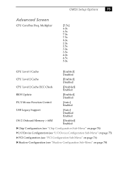
... 8.0x 2.0x 2.5x 3.0x 3.5x 4.0x 4.5x 5.0x CPU Level 1 Cache [Enabled] Disabled CPU Level 2 Cache [Enabled] Disabled CPU Level 2 Cache ECC Check [Disabled] Enabled BIOS Update [Enabled] Disabled PS/2 Mouse Function Control [Auto] Enabled USB Legacy Support [Auto] Disabled Enabled OS/2 Onboard Memory > 64M [Disabled] Enabled Chip Configuration (see "Chip...
... 8.0x 2.0x 2.5x 3.0x 3.5x 4.0x 4.5x 5.0x CPU Level 1 Cache [Enabled] Disabled CPU Level 2 Cache [Enabled] Disabled CPU Level 2 Cache ECC Check [Disabled] Enabled BIOS Update [Enabled] Disabled PS/2 Mouse Function Control [Auto] Enabled USB Legacy Support [Auto] Disabled Enabled OS/2 Onboard Memory > 64M [Disabled] Enabled Chip Configuration (see "Chip...
Reference Manual
Page 90
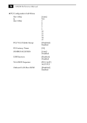
76 VAIO® Reference Manual PCI Configuration Sub-Menu Slot 1 IRQ to Slot 3 IRQ PCI/VGA Palette Snoop PCI Latency Timer SYMBIOS SCSI BIOS USB Function VGA BIOS Sequence Onboard LAN Boot ROM [Auto] NA 3 4 5 7 9 10 11 12 14 15 [Disabled] Enabled [32] [Auto] Disabled [Enabled] Disabled [PCI/AGP] AGP/PCI [Disabled] Enabled
76 VAIO® Reference Manual PCI Configuration Sub-Menu Slot 1 IRQ to Slot 3 IRQ PCI/VGA Palette Snoop PCI Latency Timer SYMBIOS SCSI BIOS USB Function VGA BIOS Sequence Onboard LAN Boot ROM [Auto] NA 3 4 5 7 9 10 11 12 14 15 [Disabled] Enabled [32] [Auto] Disabled [Enabled] Disabled [PCI/AGP] AGP/PCI [Disabled] Enabled
Reference Manual
Page 92
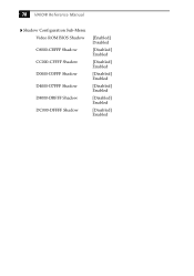
78 VAIO® Reference Manual Shadow Configuration Sub-Menu Video ROM BIOS Shadow C8000-CBFFF Shadow CC000-CFFFF Shadow D0000-D3FFF Shadow D4000-D7FFF Shadow D8000-DBFFF Shadow DC000-DFFFF Shadow [Enabled] Disabled [Disabled] Enabled [Disabled] Enabled [Disabled] Enabled [Disabled] Enabled [Disabled] Enabled [Disabled] Enabled
78 VAIO® Reference Manual Shadow Configuration Sub-Menu Video ROM BIOS Shadow C8000-CBFFF Shadow CC000-CFFFF Shadow D0000-D3FFF Shadow D4000-D7FFF Shadow D8000-DBFFF Shadow DC000-DFFFF Shadow [Enabled] Disabled [Disabled] Enabled [Disabled] Enabled [Disabled] Enabled [Disabled] Enabled [Disabled] Enabled [Disabled] Enabled
Reference Manual
Page 104
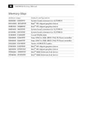
...VAIO® Reference Manual Memory Map Address range 00000000 - 0009FFFF 000A0000 - 000AFFFF 000B0000 - 000BFFFF 000F0000 - 000FFFFF 00100000 - 03FFFFFF E1800000 - E18000FF E2000000 - FFFFFFFF Default configuration System board extension for ACPI BIOS Intel® 810 chipset graphics driver Intel® 810 chipset graphics driver System board extension for ACPI BIOS... System board extension for ACPI BIOS Lucent WinModem Sony OHCI i.LINK (IEEE 1394) PCI host controller Sony OHCI i.LINK (IEEE 1394) PCI host controller Vortex ...
...VAIO® Reference Manual Memory Map Address range 00000000 - 0009FFFF 000A0000 - 000AFFFF 000B0000 - 000BFFFF 000F0000 - 000FFFFF 00100000 - 03FFFFFF E1800000 - E18000FF E2000000 - FFFFFFFF Default configuration System board extension for ACPI BIOS Intel® 810 chipset graphics driver Intel® 810 chipset graphics driver System board extension for ACPI BIOS... System board extension for ACPI BIOS Lucent WinModem Sony OHCI i.LINK (IEEE 1394) PCI host controller Sony OHCI i.LINK (IEEE 1394) PCI host controller Vortex ...
Reference Manual
Page 110
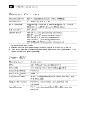
...the media. CD-ROM read : 32 X (maximum performance). CD-R write: 8X (maximum performance). The maximum writing speed is 8X. 96 VAIO® Reference Manual Drives and Controllers Diskette controller Diskette drive EIDE controller IDE hard drive* CD-RW drive‡ 82077-compatible (supports up to... 1.44 MByte 3.5-inch MFDD Supports up to hard drive capacity. The maximum reading speed is 4X (1X = 150 kbytes/s). System BIOS Make and model ROM Passwords Recovery boot block Power management Advanced features Plug and Play devices Special features Award-based Intel 82802AB Firmware Hub...
...the media. CD-ROM read : 32 X (maximum performance). CD-R write: 8X (maximum performance). The maximum writing speed is 8X. 96 VAIO® Reference Manual Drives and Controllers Diskette controller Diskette drive EIDE controller IDE hard drive* CD-RW drive‡ 82077-compatible (supports up to... 1.44 MByte 3.5-inch MFDD Supports up to hard drive capacity. The maximum reading speed is 4X (1X = 150 kbytes/s). System BIOS Make and model ROM Passwords Recovery boot block Power management Advanced features Plug and Play devices Special features Award-based Intel 82802AB Firmware Hub...
Reference Manual
Page 111
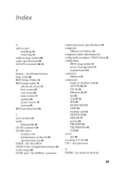
See memory module 97 See processor D DIMM - See SERIAL connector communications, specifications 95 computer lithium ion battery vii computer safety information ii configuration jumper, CMOS Clear 62 configuring BIOS setup utility 16 power management 17 system board 19 connector Ethernet 61 connectors 4-pin on modem card 63 AUX-IN ... 50 PRINTER 53 TELEPHONE 63 USB 52 cover slot 38 covering I/O slot 39 CPU - See lithium battery beep codes 85 BIOS Setup Utility 16 BIOS setup utility 16 advanced screen 73 boot screen 81 exit screen 82 main screen 71 options 69 power screen 79 screens 69...
See memory module 97 See processor D DIMM - See SERIAL connector communications, specifications 95 computer lithium ion battery vii computer safety information ii configuration jumper, CMOS Clear 62 configuring BIOS setup utility 16 power management 17 system board 19 connector Ethernet 61 connectors 4-pin on modem card 63 AUX-IN ... 50 PRINTER 53 TELEPHONE 63 USB 52 cover slot 38 covering I/O slot 39 CPU - See lithium battery beep codes 85 BIOS Setup Utility 16 BIOS setup utility 16 advanced screen 73 boot screen 81 exit screen 82 main screen 71 options 69 power screen 79 screens 69...
Reference Manual
Page 113
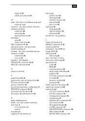
... header 46 GAME connector 57 HEADPHONES connector 58 IDE connectors 50 KEYBOARD connector 51 See Also I/O slot slot cover, removing 38 specifications audio 95 BIOS 96 communications 95 drives and controllers 96 graphics 94 I /O address map and memory map memory - See display MONITOR connector 10, 53 MOUSE ...memory module 36 side panel 22 slot cover 38 replacing 25 front panel 24 lithium battery 29 side panel 25 resolution - See SERIAL setup, BIOS 16 side panel 25 removing 22 slot - See Also system memory memory module connector 48 removing 36 specifications for 93 R radio interference v...
... header 46 GAME connector 57 HEADPHONES connector 58 IDE connectors 50 KEYBOARD connector 51 See Also I/O slot slot cover, removing 38 specifications audio 95 BIOS 96 communications 95 drives and controllers 96 graphics 94 I /O address map and memory map memory - See display MONITOR connector 10, 53 MOUSE ...memory module 36 side panel 22 slot cover 38 replacing 25 front panel 24 lithium battery 29 side panel 25 resolution - See SERIAL setup, BIOS 16 side panel 25 removing 22 slot - See Also system memory memory module connector 48 removing 36 specifications for 93 R radio interference v...


