Operating Instructions (primary manual)
Page 2
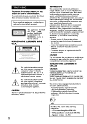
... intended to alert the user to the presence of the following measures: - A/V control amplifier STR-NX1 - Reorient or relocate the receiving antenna. - Speaker system SS-NX1 2 Do not install the appliance in the literature accompanying the appliance. This equipment generates, uses, and... INFORMATION This equipment has been tested and found to radio communications. This appliance is located on the rear exterior. The MHC-NX1 consist of uninsulated "dangerous voltage" within the product's enclosure that any changes or modifications not expressly approved in cabinet. ...
... intended to alert the user to the presence of the following measures: - A/V control amplifier STR-NX1 - Reorient or relocate the receiving antenna. - Speaker system SS-NX1 2 Do not install the appliance in the literature accompanying the appliance. This equipment generates, uses, and... INFORMATION This equipment has been tested and found to radio communications. This appliance is located on the rear exterior. The MHC-NX1 consist of uninsulated "dangerous voltage" within the product's enclosure that any changes or modifications not expressly approved in cabinet. ...
Operating Instructions (primary manual)
Page 4
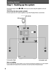
... system vertically Be sure to place the A/V control amplifier on top of the CD player/stereo cassette deck. FM antenna AM loop antenna 1 3 4 2 5 2 2 Front speaker (Right) Front speaker (Left) Note on installing Be sure to place the A/V control amplifier on top as shown in the illustration. If you set up your system...
... system vertically Be sure to place the A/V control amplifier on top of the CD player/stereo cassette deck. FM antenna AM loop antenna 1 3 4 2 5 2 2 Front speaker (Right) Front speaker (Left) Note on installing Be sure to place the A/V control amplifier on top as shown in the illustration. If you set up your system...
Operating Instructions (primary manual)
Page 5
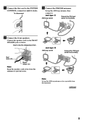
...AM CFOMA7X5IAΩL 2 Connect the front speakers. Insert only the stripped portion. Jack type A AM loop aerial Extend the FM lead aerial horizontally. Black/ Stripe (') Note Keep the speaker cords away from the antennas to the FRONT SPEAKER jacks as possible from the main unit.... Connect the speaker cords to prevent noise. continued 5 R L + + Red/ Solid (') - Jack type B ...
...AM CFOMA7X5IAΩL 2 Connect the front speakers. Insert only the stripped portion. Jack type A AM loop aerial Extend the FM lead aerial horizontally. Black/ Stripe (') Note Keep the speaker cords away from the antennas to the FRONT SPEAKER jacks as possible from the main unit.... Connect the speaker cords to prevent noise. continued 5 R L + + Red/ Solid (') - Jack type B ...
Operating Instructions (primary manual)
Page 6
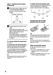
..., set the time (Step 2: Setting the time), the demonstration is off. VOLTAGE SELECTOR 230 - 240V 220V To attach the front speaker pads Attach the supplied front speaker pads to the bottom of the speakers to the super woofer connector. ] } } ] Tip With normal use the remote for a long period of time, remove the batteries... demonstration automatically ends. The demonstration appears in the display. 6 Tip You can reinforce the bass sound by connecting an optional super woofer to stabilize the speakers and prevent them from battery leakage.
..., set the time (Step 2: Setting the time), the demonstration is off. VOLTAGE SELECTOR 230 - 240V 220V To attach the front speaker pads Attach the supplied front speaker pads to the bottom of the speakers to the super woofer connector. ] } } ] Tip With normal use the remote for a long period of time, remove the batteries... demonstration automatically ends. The demonstration appears in the display. 6 Tip You can reinforce the bass sound by connecting an optional super woofer to stabilize the speakers and prevent them from battery leakage.
Operating Instructions (primary manual)
Page 25
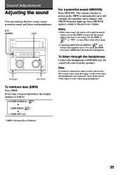
... curve changes, and GROOVE button lights up. No sound will sound distorted when you have connected a super woofer, please note that sound comes from the speakers. Set the DBFB to "DBFB" or "OFF", or cancel the sound effect (page 26). • Cancelling GROOVE sets DBFB to PHONES jack. To listen through...
... curve changes, and GROOVE button lights up. No sound will sound distorted when you have connected a super woofer, please note that sound comes from the speakers. Set the DBFB to "DBFB" or "OFF", or cancel the sound effect (page 26). • Cancelling GROOVE sets DBFB to PHONES jack. To listen through...
Operating Instructions (primary manual)
Page 36
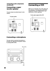
Refer to the instructions of the connected VCR, press VIDEO. To listen to the sound of each component. Adjust the microphone volume by turning MIC LEVEL. To the audio output of the plugs and the connectors. MIC LEVEL 36 - 0 ≠ g + ) + - + MIC Connecting audio components (continued) Connecting a super woofer speaker You can connect an optional microphone to the MIC jack. To super woofer Connecting a VCR Make sure to match the color of the VCR Connecting a microphone You can connect an optional super woofer speaker.
Refer to the instructions of the connected VCR, press VIDEO. To listen to the sound of each component. Adjust the microphone volume by turning MIC LEVEL. To the audio output of the plugs and the connectors. MIC LEVEL 36 - 0 ≠ g + ) + - + MIC Connecting audio components (continued) Connecting a super woofer speaker You can connect an optional microphone to the MIC jack. To super woofer Connecting a VCR Make sure to match the color of the VCR Connecting a microphone You can connect an optional super woofer speaker.
Operating Instructions (primary manual)
Page 38
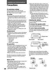
... local power supply. However, be possible to remove the CD, and may also cause this unit. Vibrating - Wipe the CD from breaking. To remove the speaker grille Use both hands and pull the grille straight forward to direct sunlight. On operation • If the stereo system is brought directly from the... A Side A Break off the cassette tab from the wall outlet (mains) if it any questions or problems concerning your stereo system, please consult your nearest Sony dealer.
... local power supply. However, be possible to remove the CD, and may also cause this unit. Vibrating - Wipe the CD from breaking. To remove the speaker grille Use both hands and pull the grille straight forward to direct sunlight. On operation • If the stereo system is brought directly from the... A Side A Break off the cassette tab from the wall outlet (mains) if it any questions or problems concerning your stereo system, please consult your nearest Sony dealer.

Operating Instructions (primary manual)
Page 39
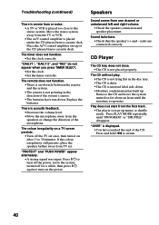
...every 10 hours of use. First, check that have set the timer, also redo "Waking up any problem persist, consult your nearest Sony dealer. Should any slack in the tape. Set the clock and timer settings again. Inserting the vinyl portion of the cleaning cassette.... Use separately sold demagnetizing cassette. For details, refer to the instructions of the speaker cord will obstruct the speaker connections. •There is a decrease in sound level - Troubleshooting If you have contact with a separately sold dry-type or...
...every 10 hours of use. First, check that have set the timer, also redo "Waking up any problem persist, consult your nearest Sony dealer. Should any slack in the tape. Set the clock and timer settings again. Inserting the vinyl portion of the cleaning cassette.... Use separately sold demagnetizing cassette. For details, refer to the instructions of the speaker cord will obstruct the speaker connections. •There is a decrease in sound level - Troubleshooting If you have contact with a separately sold dry-type or...
Operating Instructions (primary manual)
Page 40
...system turned on for a while, then press 1/u again to the stereo system. The timer does not function. •Set the clock correctly. Speakers Sound comes from TV set once, then turn it on a TV screen persists. •Turn off for about an hour until "PROGRAM" ... amplifier is inserted label side down . If the colour irregularity still persists, place the speaker farther away from one channel or unbalanced left and right volume. •Check the speaker connection and speaker placement. Press PLAY MODE repeatedly until the moisture evaporates. Move the stereo system away from...
...system turned on for a while, then press 1/u again to the stereo system. The timer does not function. •Set the clock correctly. Speakers Sound comes from TV set once, then turn it on a TV screen persists. •Turn off for about an hour until "PROGRAM" ... amplifier is inserted label side down . If the colour irregularity still persists, place the speaker farther away from one channel or unbalanced left and right volume. •Check the speaker connection and speaker placement. Press PLAY MODE repeatedly until the moisture evaporates. Move the stereo system away from...
Operating Instructions (primary manual)
Page 42
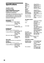
... VIDEO IN: (phono jacks) MD IN: (phono jacks) MIC: (mini jack) Outputs MD OUT: (phono jacks) PHONES: (stereo mini jack) FRONT SPEAKER: REAR SPEAKER: SUPER WOOFER: voltage 250 mV, impedance 47 kilohms voltage 450 mV, impedance 47 kilohms sensitivity 1 mV, impedance 10 kilohms voltage 250 mV impedance 1 kilohms ...section Recording system Frequency response (DOLBY NR OFF) Wow and flutter 4-track 2-channel stereo 40 - 13,000 Hz (±3 dB), using Sony TYPE I cassette 40 - 14,000 Hz (±3 dB), using Sony TYPE II cassette ±0.15% W.Peak (IEC) 0.1% W.RMS (NAB) ±0.2% W.Peak (DIN) 42
... VIDEO IN: (phono jacks) MD IN: (phono jacks) MIC: (mini jack) Outputs MD OUT: (phono jacks) PHONES: (stereo mini jack) FRONT SPEAKER: REAR SPEAKER: SUPER WOOFER: voltage 250 mV, impedance 47 kilohms voltage 450 mV, impedance 47 kilohms sensitivity 1 mV, impedance 10 kilohms voltage 250 mV impedance 1 kilohms ...section Recording system Frequency response (DOLBY NR OFF) Wow and flutter 4-track 2-channel stereo 40 - 13,000 Hz (±3 dB), using Sony TYPE I cassette 40 - 14,000 Hz (±3 dB), using Sony TYPE II cassette ±0.15% W.Peak (IEC) 0.1% W.RMS (NAB) ±0.2% W.Peak (DIN) 42
Operating Instructions (primary manual)
Page 43
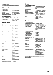
...) SW: 5.95 - 17.90 MHz (with the interval set at 5 kHz) Antenna AM loop antenna Antenna terminals External antenna terminal Intermediate frequency 450 kHz Speaker Front Speaker (SS-NX1) Speaker system Speaker units Woofer: Tweeter: Nominal impedance Dimensions (w/h/d) Mass 2-way, bass-reflex type, magnetically shielded type 17 cm (63/4 in.), cone type 2.5 cm (1 in.), dome...
...) SW: 5.95 - 17.90 MHz (with the interval set at 5 kHz) Antenna AM loop antenna Antenna terminals External antenna terminal Intermediate frequency 450 kHz Speaker Front Speaker (SS-NX1) Speaker system Speaker units Woofer: Tweeter: Nominal impedance Dimensions (w/h/d) Mass 2-way, bass-reflex type, magnetically shielded type 17 cm (63/4 in.), cone type 2.5 cm (1 in.), dome...
Operating Instructions (primary manual)
Page 44
...19 Resetting the system 41 S Saving recordings 38 Selecting the audio emphasis 26 Setting the time 7 Shuffle Play 19 Sleep Timer 32 Sound adjustment 25 Speakers 36 Station name 30 T, U, V, W, X, Y, Z Timer falling asleep to music 32 timer recording 34 waking up to music 33 Troubleshooting 39 ...Tuner 12, 30 Tuning interval 8 44 Sony Corporation Printed in Malaysia Index A Adjusting the graphic equalizer 28 the sound 25 the volume 11, 16 Aerials 5, 37 Automatic Source Selection 11, 13, 16...
...19 Resetting the system 41 S Saving recordings 38 Selecting the audio emphasis 26 Setting the time 7 Shuffle Play 19 Sleep Timer 32 Sound adjustment 25 Speakers 36 Station name 30 T, U, V, W, X, Y, Z Timer falling asleep to music 32 timer recording 34 waking up to music 33 Troubleshooting 39 ...Tuner 12, 30 Tuning interval 8 44 Sony Corporation Printed in Malaysia Index A Adjusting the graphic equalizer 28 the sound 25 the volume 11, 16 Aerials 5, 37 Automatic Source Selection 11, 13, 16...
Service Manual
Page 1
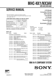
...COMPONENT SYSTEM MICROFILM 9-928-979-11 Sony Corporation Home Audio Company 99H001688-1 Printed in Japan ©1999.8 Published by Quality Assurance Dept. MHC-NX1/NX3AV HCD-NX1/HCR-NX3 SERVICE MANUAL • MHC-NX1/NX3AV is composed of STR-NX3 and HTC-NX1. No. As for the service...STR-NX1 and HTC-NX1. COMPONENT MODEL NAME FOR MHC-NX1/NX3AV US Model Canadian Model AEP Model UK Model E Model MHC-NX1/NX3AV TUNER,AMPLIFIER MHC-NX1 STR-NX1 MHC-NX3AV STR-NX3 Tourist Model MHC-NX1 CD PLAYER ,TAPE DECK FRONT SPEAKER SYSTEM CENTER/REAR SPEAKER SYSTEM HTC-NX1 SS-NX1 SS-RC100 HCD-NX1 is...
...COMPONENT SYSTEM MICROFILM 9-928-979-11 Sony Corporation Home Audio Company 99H001688-1 Printed in Japan ©1999.8 Published by Quality Assurance Dept. MHC-NX1/NX3AV HCD-NX1/HCR-NX3 SERVICE MANUAL • MHC-NX1/NX3AV is composed of STR-NX3 and HTC-NX1. No. As for the service...STR-NX1 and HTC-NX1. COMPONENT MODEL NAME FOR MHC-NX1/NX3AV US Model Canadian Model AEP Model UK Model E Model MHC-NX1/NX3AV TUNER,AMPLIFIER MHC-NX1 STR-NX1 MHC-NX3AV STR-NX3 Tourist Model MHC-NX1 CD PLAYER ,TAPE DECK FRONT SPEAKER SYSTEM CENTER/REAR SPEAKER SYSTEM HTC-NX1 SS-NX1 SS-RC100 HCD-NX1 is...
Service Manual
Page 5
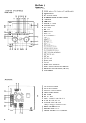
... 7 DVD 5.1CH INPUT jacks (STR-NX3) 8 SUPER WOOFER OUT jack 9 VOLTAGE SELECTOR switch (Malaysia, Singapore and Tourist models) q; Rear Panel - 12 3 4 5 6 7 8 q; FRONT SPEAKER terminals qa REAR SPEAKER terminals qs CENTER SPEAKER terminals (STR-NX3) qs qf qh 7 9 qa qd qg qj 1 2 3 4 5 6 wf wg wh wj wk wl e; SECTION 2 GENERAL 1 TIMER indicator (US, Canadian...
... 7 DVD 5.1CH INPUT jacks (STR-NX3) 8 SUPER WOOFER OUT jack 9 VOLTAGE SELECTOR switch (Malaysia, Singapore and Tourist models) q; Rear Panel - 12 3 4 5 6 7 8 q; FRONT SPEAKER terminals qa REAR SPEAKER terminals qs CENTER SPEAKER terminals (STR-NX3) qs qf qh 7 9 qa qd qg qj 1 2 3 4 5 6 wf wg wh wj wk wl e; SECTION 2 GENERAL 1 TIMER indicator (US, Canadian...
Service Manual
Page 25
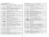
...power on (Used for the STR-NX3 only) 26 STK POWER O Power amplifier on/off selection signal output terminal "L": standby mode, "H": on 27 SPEAKER PROTECT I Protect on/off detection signal input from the remote control receiver (IC601) 6 LINE MUTE O Line muting on/off control signal output terminal ...signal input from the speaker protect circuit "L": protect on, "H": protect off 28 SOFT-TEST O Output terminal for the software test Not used (open) 29 IIC CLK I/O Communication data reading clock signal input or transfer clock signal output with the CPU on the HTC-NX1 30 IIC DATA ...
...power on (Used for the STR-NX3 only) 26 STK POWER O Power amplifier on/off selection signal output terminal "L": standby mode, "H": on 27 SPEAKER PROTECT I Protect on/off detection signal input from the remote control receiver (IC601) 6 LINE MUTE O Line muting on/off control signal output terminal ...signal input from the speaker protect circuit "L": protect on, "H": protect off 28 SOFT-TEST O Output terminal for the software test Not used (open) 29 IIC CLK I/O Communication data reading clock signal input or transfer clock signal output with the CPU on the HTC-NX1 30 IIC DATA ...
Service Manual
Page 38
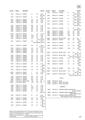
... TERMINAL > TM801 1-537-240-11 TERMINAL BOARD (CHECKER PIN) (FRONT SPEAKER) TM802 1-537-240-11 TERMINAL BOARD (CHECKER PIN) (REAR SPEAKER) (NX1) TM802 1-537-510-11 TERMINAL BOARD (SPEAKER) (6P) (REAR SPEAKER, CENTER SPEAKER) (NX3) The components identified by Les composants identifiés par une mark...1/4W 33K 5% 1/4W 68K 5% 1/4W 2.2K 5% 1/4W 22K 5% 1/4W 10K 5% 1/4W 22K 5% 1/4W 1 5% 1/4W F 100K 5% 1/4W 100K 5% 1/4W 10K 5% 1/4W (NX1: AEP, UK) 12K 5% 1/4W (US, CND/NX3: AEP, UK) 18K 5% 1/4W (E, AUS, JE) 15K 5% 1/4W 33K 5% 1/4W 4.7K 5% 1/4W 22K 5% 1/4W 33K ...
... TERMINAL > TM801 1-537-240-11 TERMINAL BOARD (CHECKER PIN) (FRONT SPEAKER) TM802 1-537-240-11 TERMINAL BOARD (CHECKER PIN) (REAR SPEAKER) (NX1) TM802 1-537-510-11 TERMINAL BOARD (SPEAKER) (6P) (REAR SPEAKER, CENTER SPEAKER) (NX3) The components identified by Les composants identifiés par une mark...1/4W 33K 5% 1/4W 68K 5% 1/4W 2.2K 5% 1/4W 22K 5% 1/4W 10K 5% 1/4W 22K 5% 1/4W 1 5% 1/4W F 100K 5% 1/4W 100K 5% 1/4W 10K 5% 1/4W (NX1: AEP, UK) 12K 5% 1/4W (US, CND/NX3: AEP, UK) 18K 5% 1/4W (E, AUS, JE) 15K 5% 1/4W 33K 5% 1/4W 4.7K 5% 1/4W 22K 5% 1/4W 33K ...
Service Manual
Page 96
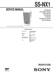
SERVICE MANUAL SS-NX1 US Model Canadian Model AEP Model UK Model E Model Australian Model Tourist Model Photo: AEP model • SS-NX1 is the speaker system in MHC-NX1/NX3AV. SPECIFICATIONS MICROFILM SPEAKER SYSTEM
SERVICE MANUAL SS-NX1 US Model Canadian Model AEP Model UK Model E Model Australian Model Tourist Model Photo: AEP model • SS-NX1 is the speaker system in MHC-NX1/NX3AV. SPECIFICATIONS MICROFILM SPEAKER SYSTEM

Service Manual
Page 97
...Quality Assurance Dept. Description 7-685-661-11 SCREW +BVTP 4X12 TYPE2 N-S 4-224-600-01 SCREW (3.5X16), +K TAPPING 1-529-439-11 SPEAKER (2.5cm) (TWEETER) 1-529-440-11 SPEAKER (16cm) (WOOFER) Remark 4 X-4951-750-1 RING ASSY, TW 5 4-986-971-01 SCREW (3.5) 6 4-874-614-61 SCREW +BVTP...-223-11 MOUNTED PC BOARD ACCESSORIES & PACKING MATERIALS 1-769-433-21 CORD, SPEAKER (AEP, UK) 3-867-790-11 MANUAL, INSTRUCTION (ENGLISH, FRENCH, GERMAN, SWEDISH, RUSSIAN) (AEP, UK) 9-928-982-11 2 Sony Corporation Home Audio Company 99H051688-1 Printed in the exploded views are seldom required for ...
...Quality Assurance Dept. Description 7-685-661-11 SCREW +BVTP 4X12 TYPE2 N-S 4-224-600-01 SCREW (3.5X16), +K TAPPING 1-529-439-11 SPEAKER (2.5cm) (TWEETER) 1-529-440-11 SPEAKER (16cm) (WOOFER) Remark 4 X-4951-750-1 RING ASSY, TW 5 4-986-971-01 SCREW (3.5) 6 4-874-614-61 SCREW +BVTP...-223-11 MOUNTED PC BOARD ACCESSORIES & PACKING MATERIALS 1-769-433-21 CORD, SPEAKER (AEP, UK) 3-867-790-11 MANUAL, INSTRUCTION (ENGLISH, FRENCH, GERMAN, SWEDISH, RUSSIAN) (AEP, UK) 9-928-982-11 2 Sony Corporation Home Audio Company 99H051688-1 Printed in the exploded views are seldom required for ...


