
Service Manual
Page 1
... DATE: 7/2/01 ALL REVISIONS AND UPDATES TO THE ORIGINAL MANUAL ARE APPENDED TO THE END OF THE PDF FILE. SERVICE MANUAL RA-6 CHASSIS MODEL NAME KP-43HT20 KP-43HT20 KP-53HS20 KP-53HS20 KP-53HS30 KP-53HS30 KP-61HS20 KP-61HS20 KP-61HS30 KP-61HS30 REMOTE COMMANDER DESTINATION CHASSIS NO. REVISION DATE 7/2/01 REVISION TYPE SUBJECT No revisions or updates are applicable at...
... DATE: 7/2/01 ALL REVISIONS AND UPDATES TO THE ORIGINAL MANUAL ARE APPENDED TO THE END OF THE PDF FILE. SERVICE MANUAL RA-6 CHASSIS MODEL NAME KP-43HT20 KP-43HT20 KP-53HS20 KP-53HS20 KP-53HS30 KP-53HS30 KP-61HS20 KP-61HS20 KP-61HS30 KP-61HS30 REMOTE COMMANDER DESTINATION CHASSIS NO. REVISION DATE 7/2/01 REVISION TYPE SUBJECT No revisions or updates are applicable at...

Service Manual
Page 3
... SH-63Trd are at earth ground. Checking for unsoldered or poorly-soldered connections. KP-43HT20/53HS20/53HS30/61HS20/61HS30 RM-Y908 RM-Y908 RM-Y908 RM-Y908 RM-Y908 SAFETY CHECK-OUT ( US model only ) After correcting the original service problem, perfom the following safety checks before releasing the set to the customer...
... SH-63Trd are at earth ground. Checking for unsoldered or poorly-soldered connections. KP-43HT20/53HS20/53HS30/61HS20/61HS30 RM-Y908 RM-Y908 RM-Y908 RM-Y908 RM-Y908 SAFETY CHECK-OUT ( US model only ) After correcting the original service problem, perfom the following safety checks before releasing the set to the customer...

Service Manual
Page 5
...SET-UP ADJUSTMENTS 3-2. DEFOCUS ADJUSTMENT (BLUE 13 3-10 .ELECTRICAL ADJUSTMENT BY REMOTE COMMANDER 14 4. CIRCUIT ADJUSTMENTS 4-1. Page ---- 5. WAVEFORMS 85 6-6. COVER (KP-53HS20/HS30/61HS20/HS30 93 7-3. PICTuRE TUBE 96 8. DIAGRAMS 6-1. DISASSEMBLY 2-1. 2-2. 2-3. 2-4. 2-5. 2-6. 2-7. 2-8. 2-10. 2-9. 2-12. 2-11. 2-13. 2-14... Section ------ REAR BOARD REMOVAL 8 CHASSIS ASSY REMOVAL 8 SERVICE POSITION 8 H2 BOARD REMOVAL 8 H1 BOARD REMOVAL 9 H3 BOARD REMOVAL (KP-43HT20 9 H3 BOARD REMOVAL (KP-53HS20/53HS30/61HS20/61HS30 9 MIRROR COVER REMOVAL 9 H4 BOARD AND S ...
...SET-UP ADJUSTMENTS 3-2. DEFOCUS ADJUSTMENT (BLUE 13 3-10 .ELECTRICAL ADJUSTMENT BY REMOTE COMMANDER 14 4. CIRCUIT ADJUSTMENTS 4-1. Page ---- 5. WAVEFORMS 85 6-6. COVER (KP-53HS20/HS30/61HS20/HS30 93 7-3. PICTuRE TUBE 96 8. DIAGRAMS 6-1. DISASSEMBLY 2-1. 2-2. 2-3. 2-4. 2-5. 2-6. 2-7. 2-8. 2-10. 2-9. 2-12. 2-11. 2-13. 2-14... Section ------ REAR BOARD REMOVAL 8 CHASSIS ASSY REMOVAL 8 SERVICE POSITION 8 H2 BOARD REMOVAL 8 H1 BOARD REMOVAL 9 H3 BOARD REMOVAL (KP-43HT20 9 H3 BOARD REMOVAL (KP-53HS20/53HS30/61HS20/61HS30 9 MIRROR COVER REMOVAL 9 H4 BOARD AND S ...

Service Manual
Page 7
...to " 0 " it will not be sure to return the results display to the standby mode) 2. DISPLAY b Channel 5 b VOL - DISPLAY b Channel 5 b VOL + b POWER (Service Mode) 3. Self-diagnosis screen display SELF DIAGNOSIS 2 : +B OCP N/A 3 : +B OVP N/A 4 : V STOP 0 5 : AKB 1 10 : WDT 24 Numeral "0" means that...diagnosis screen displays • In cases of entering the service mode (volume + ). Self-Diagnosis Screen Display • The results display is not automatically cleared. Numeral "1" means a fault was detected. KP-43HT20/53HS20/53HS30/61HS20/61HS30 RM-Y908 RM-Y908 RM-Y908 RM-Y908 RM...
...to " 0 " it will not be sure to return the results display to the standby mode) 2. DISPLAY b Channel 5 b VOL - DISPLAY b Channel 5 b VOL + b POWER (Service Mode) 3. Self-diagnosis screen display SELF DIAGNOSIS 2 : +B OCP N/A 3 : +B OVP N/A 4 : V STOP 0 5 : AKB 1 10 : WDT 24 Numeral "0" means that...diagnosis screen displays • In cases of entering the service mode (volume + ). Self-Diagnosis Screen Display • The results display is not automatically cleared. Numeral "1" means a fault was detected. KP-43HT20/53HS20/53HS30/61HS20/61HS30 RM-Y908 RM-Y908 RM-Y908 RM-Y908 RM...

Service Manual
Page 9
... 4x20 3 Six screws (+BVTP4x12) 4 H2 board 5 Button, multi 1 Cap, speker grille 2 Chassis assy - 8 - 2-1. REAR BOARD REMOVAL KP-43HT20/53HS20/53HS30/61HS20/61HS30 RM-Y908 RM-Y908 RM-Y908 RM-Y908 RM-Y908 SECTION 2 DISASSEMBLY 2 Rear board 2-3. SERVICE POSITION 1 Disconnect CN17, 18, 19 on A board. After checking, turn over the covers and secure them...
... 4x20 3 Six screws (+BVTP4x12) 4 H2 board 5 Button, multi 1 Cap, speker grille 2 Chassis assy - 8 - 2-1. REAR BOARD REMOVAL KP-43HT20/53HS20/53HS30/61HS20/61HS30 RM-Y908 RM-Y908 RM-Y908 RM-Y908 RM-Y908 SECTION 2 DISASSEMBLY 2 Rear board 2-3. SERVICE POSITION 1 Disconnect CN17, 18, 19 on A board. After checking, turn over the covers and secure them...

Service Manual
Page 13
...Please note, that the bars at the center of CR board, CG board and CB board. 5. After adjusting the items 3-5. KP-43HT20/53HS20/53HS30/61HS20/61HS30 RM-Y908 RM-Y908 RM-Y908 RM-Y908 RM-Y908 SECTION 3 SET-UP ADJUSTMENTS 3-1. Turn the red VR on JIG.... the Monoscope signal. 2. Connect G2 JIG. 3. "crossbatch+borderline(black)" - Connect an oscilloscope to the funnel-shaped portion (neck) of the service mode and the remote commander, please refer the item 3-9. Focus VR Adjustment, 3-6. 2-Pole Magnet Adjustment and 3-7. 4-Pole Magnet Adjustment, adjust again...
...Please note, that the bars at the center of CR board, CG board and CB board. 5. After adjusting the items 3-5. KP-43HT20/53HS20/53HS30/61HS20/61HS30 RM-Y908 RM-Y908 RM-Y908 RM-Y908 RM-Y908 SECTION 3 SET-UP ADJUSTMENTS 3-1. Turn the red VR on JIG.... the Monoscope signal. 2. Connect G2 JIG. 3. "crossbatch+borderline(black)" - Connect an oscilloscope to the funnel-shaped portion (neck) of the service mode and the remote commander, please refer the item 3-9. Focus VR Adjustment, 3-6. 2-Pole Magnet Adjustment and 3-7. 4-Pole Magnet Adjustment, adjust again...

Service Manual
Page 14
KP-43HT20/53HS20/53HS30/61HS20/61HS30 RM-Y908 RM-Y908 RM-Y908 RM-Y908 RM-Y908 3-5. After adjusting... show only the red color. 5. Note: Instead of item 2 you can cut off the unnecessary color beams by controlling the service mode 2150P-2 1 RGBS. Fig. 3-7 - 13 - Cover the both red and blue picture lenses with high luminace signal,...1. Lens Fig. 3-5 B Center of items 2, 4 and 6, you can cut off the unnecessary color beams by controlling the service mode 2150P-2 1 RGBS. 3-7. Adjust the green centering magnet to put the center of the monoscope signal to show only the ...
KP-43HT20/53HS20/53HS30/61HS20/61HS30 RM-Y908 RM-Y908 RM-Y908 RM-Y908 RM-Y908 3-5. After adjusting... show only the red color. 5. Note: Instead of item 2 you can cut off the unnecessary color beams by controlling the service mode 2150P-2 1 RGBS. Fig. 3-7 - 13 - Cover the both red and blue picture lenses with high luminace signal,...1. Lens Fig. 3-5 B Center of items 2, 4 and 6, you can cut off the unnecessary color beams by controlling the service mode 2150P-2 1 RGBS. 3-7. Adjust the green centering magnet to put the center of the monoscope signal to show only the ...

Service Manual
Page 15
...the Remote Commander. (Press each button within a second.) 3. Digital multimeter 4. Turn power off ) 2. Standby mode. (Power off . Data 3D-COMB 0 0 SERVICE NRMD TV WSL : XXX F / A FLAG : XXXXXXXX CBA FLAG : XXXXXXXX DISPLAY Adjustment item up Adjustment item down ENTER 3. Press [MUTING] then [ENTER] to recover the... 5 n VOL (+) n TV POWER on the Remote Commander to exit. 2. If you press 2(Category up Data down Category down Category up Data up ), Service mode changes in the PJE mode, refer to read the memory. 8. KP-43HT20/53HS20/53HS30/61HS20/61HS30 RM-Y908 RM-Y908 ...
...the Remote Commander. (Press each button within a second.) 3. Digital multimeter 4. Turn power off ) 2. Standby mode. (Power off . Data 3D-COMB 0 0 SERVICE NRMD TV WSL : XXX F / A FLAG : XXXXXXXX CBA FLAG : XXXXXXXX DISPLAY Adjustment item up Adjustment item down ENTER 3. Press [MUTING] then [ENTER] to recover the... 5 n VOL (+) n TV POWER on the Remote Commander to exit. 2. If you press 2(Category up Data down Category down Category up Data up ), Service mode changes in the PJE mode, refer to read the memory. 8. KP-43HT20/53HS20/53HS30/61HS20/61HS30 RM-Y908 RM-Y908 ...

Service Manual
Page 16
...=0 0 SNNR=1 0 SVideo1 1 Video5&6 0 Video5&6 2 SNNR=2 0 CVideo2 0 SNNR=3 0 SVideo2 1 CVideo3 0 SVideo3 1 CVideo4 0 NRMD=2 4 NRMD=3 4 KP-43HT20/53HS20/53HS30/61HS20/61HS30 RM-Y908 RM-Y908 RM-Y908 RM-Y908 RM-Y908 - 15 - 3D-COMB uPD64082 Reg.No & Name FUNCTION 27 OP Option: Selection of...=1 0 1 1 1 12 * 8 * 3 * NRMD=0 NRMD=1 4 4 3 * Svideo Standard Non-standard 3 3 Note: * shows common data. 4. SERVICE MODE LIST Note: • shaded items are different a little in the sets individually. Svideo Standard Non-standard 0 0 NRMD=2 2 10 5 5 NRMD=3 2 10...
...=0 0 SNNR=1 0 SVideo1 1 Video5&6 0 Video5&6 2 SNNR=2 0 CVideo2 0 SNNR=3 0 SVideo2 1 CVideo3 0 SVideo3 1 CVideo4 0 NRMD=2 4 NRMD=3 4 KP-43HT20/53HS20/53HS30/61HS20/61HS30 RM-Y908 RM-Y908 RM-Y908 RM-Y908 RM-Y908 - 15 - 3D-COMB uPD64082 Reg.No & Name FUNCTION 27 OP Option: Selection of...=1 0 1 1 1 12 * 8 * 3 * NRMD=0 NRMD=1 4 4 3 * Svideo Standard Non-standard 3 3 Note: * shows common data. 4. SERVICE MODE LIST Note: • shaded items are different a little in the sets individually. Svideo Standard Non-standard 0 0 NRMD=2 2 10 5 5 NRMD=3 2 10...

Service Manual
Page 24
... used for the direct setting. SNNR data is used for the (+) offset setting. SNNR data is used for the (-) offset setting. KP-43HT20/53HS20/53HS30/61HS20/61HS30 RM-Y908 RM-Y908 RM-Y908 RM-Y908 RM-Y908 - 23 - On-Screen Display (OSD) Reg.No & Name FUNCTION 0... CRIT Charge/Discharge timing control for slice voltage level 0 6 CHMK Horizontal mask width 42 7 FPOL Field polarity selection 1 8 LANG 0 9 DATA Swwitch for CCD service/test data 0 10 VCHIP Selection of Vchip controls 1 OPTIONS Reg.No & Name FUNCTION 0 DLY1 Power-On to RLY timing = DLY1 x 50ms 2 1 DLY2 Power...
... used for the direct setting. SNNR data is used for the (+) offset setting. SNNR data is used for the (-) offset setting. KP-43HT20/53HS20/53HS30/61HS20/61HS30 RM-Y908 RM-Y908 RM-Y908 RM-Y908 RM-Y908 - 23 - On-Screen Display (OSD) Reg.No & Name FUNCTION 0... CRIT Charge/Discharge timing control for slice voltage level 0 6 CHMK Horizontal mask width 42 7 FPOL Field polarity selection 1 8 LANG 0 9 DATA Swwitch for CCD service/test data 0 10 VCHIP Selection of Vchip controls 1 OPTIONS Reg.No & Name FUNCTION 0 DLY1 Power-On to RLY timing = DLY1 x 50ms 2 1 DLY2 Power...

Service Manual
Page 25
... BVCS 30 BVCW 31 RHCS 32 RHCW Contents Switch of display for fine adjustment data Service copy adjustment Service all copy adjustment Osd horizontal position of PJED service menu Osd vertical position of PJED service menu Start position of fine adjustment Start line of fine adjustment Value of V1 delay ... - 0 - - 0 127 43:134 53:134 61:134 0 2047 43:50 53:50 61:50 0 2047 0 0 2047 43:510 53:510 61:510 PJ Engine ITEM ITEM No. Blue vertical center offset data for Auto Regi. Pattern Lower vertical position Auto Regi. KP-43HT20/53HS20/53HS30/61HS20/61HS30 RM-Y908 RM-Y908 RM-Y908...
... BVCS 30 BVCW 31 RHCS 32 RHCW Contents Switch of display for fine adjustment data Service copy adjustment Service all copy adjustment Osd horizontal position of PJED service menu Osd vertical position of PJED service menu Start position of fine adjustment Start line of fine adjustment Value of V1 delay ... - 0 - - 0 127 43:134 53:134 61:134 0 2047 43:50 53:50 61:50 0 2047 0 0 2047 43:510 53:510 61:510 PJ Engine ITEM ITEM No. Blue vertical center offset data for Auto Regi. Pattern Lower vertical position Auto Regi. KP-43HT20/53HS20/53HS30/61HS20/61HS30 RM-Y908 RM-Y908 RM-Y908...

Service Manual
Page 26
... adjustment Red fine adjustment Blue coarse adjustment SUB DEFLECTION ADJUSTMENT (Item 3-10-4) Blue fine adjustment : middle 1) Set NTSC Full mode. 2) Enter the Service mode, and select "PJE". Place the caps on the power and wait for Adjustment 1. Memorize the FLASH FOCUS offset data End 1 V-Size 5. Adjust...NTSC Full mode to initialize the data in the other mode as the occasion demands. KP-43HT20/53HS20/53HS30/61HS20/61HS30 RM-Y908 RM-Y908 RM-Y908 RM-Y908 RM-Y908 3-11. Enter the Service mode, and select "2150D-1" . 4. Copy the dada of NTSC Full mode adjustment,...
... adjustment Red fine adjustment Blue coarse adjustment SUB DEFLECTION ADJUSTMENT (Item 3-10-4) Blue fine adjustment : middle 1) Set NTSC Full mode. 2) Enter the Service mode, and select "PJE". Place the caps on the power and wait for Adjustment 1. Memorize the FLASH FOCUS offset data End 1 V-Size 5. Adjust...NTSC Full mode to initialize the data in the other mode as the occasion demands. KP-43HT20/53HS20/53HS30/61HS20/61HS30 RM-Y908 RM-Y908 RM-Y908 RM-Y908 RM-Y908 3-11. Enter the Service mode, and select "2150D-1" . 4. Copy the dada of NTSC Full mode adjustment,...

Service Manual
Page 27
... not to NVM. Operation Method for Projector Engine Mode MUTING TV POWER Category up Adjustment item up Adjustment item down Category down Initialize data (Not stored) MENU data up V : Data (V) down 5) Before returning to the Service mode, press "MUTING" +"ENTER" buttons on the commander ... Item v, B direction:Data up , down 3) Select "GRN CENT" . moves up ) • 5 : Changes adjustment category. (category No. KP-43HT20/53HS20/53HS30/61HS20/61HS30 RM-Y908 RM-Y908 RM-Y908 RM-Y908 RM-Y908 3-11-3. moves up ) : Marker moves clockwise from center to center. (in fine adjustment...
... not to NVM. Operation Method for Projector Engine Mode MUTING TV POWER Category up Adjustment item up Adjustment item down Category down Initialize data (Not stored) MENU data up V : Data (V) down 5) Before returning to the Service mode, press "MUTING" +"ENTER" buttons on the commander ... Item v, B direction:Data up , down 3) Select "GRN CENT" . moves up ) • 5 : Changes adjustment category. (category No. KP-43HT20/53HS20/53HS30/61HS20/61HS30 RM-Y908 RM-Y908 RM-Y908 RM-Y908 RM-Y908 3-11-3. moves up ) : Marker moves clockwise from center to center. (in fine adjustment...

Service Manual
Page 30
... data to the NVM. 1. Registration Data Writing 1) After each mode. 3-12. Exit the service mode. 3-13. In order for NTSC Full mode finished and the data have already been written. 2. Select the PJE mode. 3. KP-43HT20/53HS20/53HS30/61HS20/61HS30 RM-Y908 RM-Y908 RM-Y908 RM-Y908 RM-Y908 14) Press "9" button...
... data to the NVM. 1. Registration Data Writing 1) After each mode. 3-12. Exit the service mode. 3-13. In order for NTSC Full mode finished and the data have already been written. 2. Select the PJE mode. 3. KP-43HT20/53HS20/53HS30/61HS20/61HS30 RM-Y908 RM-Y908 RM-Y908 RM-Y908 RM-Y908 14) Press "9" button...
Service Manual
Page 31
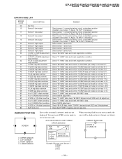
...69 HLB" data, check "73 HRIV" data and check SIZE and LIN adjustment. You must enter PJED service mode to see below). SENSOR POSITIONS 0 ERROR G LO LEVEL S3 1 2 3 - 30 - KP-43HT20/53HS20/53HS30/61HS20/61HS30 RM-Y908 RM-Y908 RM-Y908 RM-Y908 RM-Y908 ERROR CODE LIST ERROR CODE DESCRIPTION 00...52 V SKEW regi data overdrow 53 H SKEW regi data overdrow 54 H LIN regi data overdrow 55 H SIZE regi data overdrow 60 H or V CENT offset overflow 61 H or V SKEW offset overflow 62 H SIZE or LIN offset overflow 70 H or V CENT offset overdrow 71 H or V SKEW offset overdrow 72 H SIZE ...
...69 HLB" data, check "73 HRIV" data and check SIZE and LIN adjustment. You must enter PJED service mode to see below). SENSOR POSITIONS 0 ERROR G LO LEVEL S3 1 2 3 - 30 - KP-43HT20/53HS20/53HS30/61HS20/61HS30 RM-Y908 RM-Y908 RM-Y908 RM-Y908 RM-Y908 ERROR CODE LIST ERROR CODE DESCRIPTION 00...52 V SKEW regi data overdrow 53 H SKEW regi data overdrow 54 H LIN regi data overdrow 55 H SIZE regi data overdrow 60 H or V CENT offset overflow 61 H or V SKEW offset overflow 62 H SIZE or LIN offset overflow 70 H or V CENT offset overdrow 71 H or V SKEW offset overdrow 72 H SIZE ...

Service Manual
Page 32
...into memory. VIDEO MODE : Pro PICTURE : maximum COLOR : center HUE : +4 steps Signal : off 3. TV terminal (sub) : no signal VIDEO terminal (main) : color-bar signal 2. Set to P & P mode, and set to service mode. 4. P & P SUB-HUE AND SUB-COLOR ADJUSTMENT (SHUE, SCOL) 1. Select " 2103-1-02... 2.00 ± 0.05Vp-p. 7. TV terminal (sub) : no signal VIDEO terminal (main) : color-bar signal 2. P & P SUB CONTRAST ADJUSTMENT (VIDEO) (SCON) 1. Receive the signal. Set to P & P mode, set to have VB1 KP-43HT20/53HS20/53HS30/61HS20/61HS30 RM-Y908 RM-Y908 RM-Y908...
...into memory. VIDEO MODE : Pro PICTURE : maximum COLOR : center HUE : +4 steps Signal : off 3. TV terminal (sub) : no signal VIDEO terminal (main) : color-bar signal 2. Set to P & P mode, and set to service mode. 4. P & P SUB-HUE AND SUB-COLOR ADJUSTMENT (SHUE, SCOL) 1. Select " 2103-1-02... 2.00 ± 0.05Vp-p. 7. TV terminal (sub) : no signal VIDEO terminal (main) : color-bar signal 2. P & P SUB CONTRAST ADJUSTMENT (VIDEO) (SCON) 1. Receive the signal. Set to P & P mode, set to have VB1 KP-43HT20/53HS20/53HS30/61HS20/61HS30 RM-Y908 RM-Y908 RM-Y908...

Service Manual
Page 93
... shading and mark ! SECTION 7 EXPLODED VIEWS • Items marked " * " are not stocked since they are seldom required for routine service • The construction parts of an assembled part are critical for routine service. Ne les remplacer que par une piece portant le numero specifie. 8 8 11 6 13 6 4 38 3 2 5 1 38 7 38 6...23 22 21 31 32 27 37 13 19 17 20 18 12 13 14 13 13 40 28 35 29 30 36 KP-43HT20/53HS20/53HS30/61HS20/61HS30 RM-Y908 RM-Y908 RM-Y908 RM-Y908 RM-Y908 R--E-F-.-N--O-. -P-A-R--T-N--O-. -D-E-S-C--R-I-P-T-I -O-N- 25 4-082-300-11 DOOR, SIDE TERMINAL ...
... shading and mark ! SECTION 7 EXPLODED VIEWS • Items marked " * " are not stocked since they are seldom required for routine service • The construction parts of an assembled part are critical for routine service. Ne les remplacer que par une piece portant le numero specifie. 8 8 11 6 13 6 4 38 3 2 5 1 38 7 38 6...23 22 21 31 32 27 37 13 19 17 20 18 12 13 14 13 13 40 28 35 29 30 36 KP-43HT20/53HS20/53HS30/61HS20/61HS30 RM-Y908 RM-Y908 RM-Y908 RM-Y908 RM-Y908 R--E-F-.-N--O-. -P-A-R--T-N--O-. -D-E-S-C--R-I-P-T-I -O-N- 25 4-082-300-11 DOOR, SIDE TERMINAL ...

Service Manual
Page 98
... B, unless otherwise noted. Should replacement be anticipated when ordering these items. • CAPACITORS PF : µµ F • There are seldom required for routine service. KP-43HT20/53HS20/53HS30/61HS20/61HS30 RM-Y908 RM-Y908 RM-Y908 RM-Y908 RM-Y908 SECTION 8 ELECTRICAL PARTS LIST CR The components identified by the reference number, please...
... B, unless otherwise noted. Should replacement be anticipated when ordering these items. • CAPACITORS PF : µµ F • There are seldom required for routine service. KP-43HT20/53HS20/53HS30/61HS20/61HS30 RM-Y908 RM-Y908 RM-Y908 RM-Y908 RM-Y908 SECTION 8 ELECTRICAL PARTS LIST CR The components identified by the reference number, please...
Service Manual
Page 133
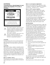
... CATV system installer This reminder is provided to call the CATV system installer's attention to adjust convergence. MODELS: KP-43HT20, KP-53HS20, KP-53HS30, KP61HS20, KP-61HS30 Please keep the brightness and contrast functions at a high brightness or contrast setting, the image can radiate ... remote control RM-Y908. If a fixed (non-moving) pattern such as practical. NO USER-SERVICEABLE PARTS INSIDE. CAUTION To prevent electric shock, do not expose the projection TV to operate this equipment. These types of this polarized AC plug with radio communications. FLASH FOCUS&#...
... CATV system installer This reminder is provided to call the CATV system installer's attention to adjust convergence. MODELS: KP-43HT20, KP-53HS20, KP-53HS30, KP61HS20, KP-61HS30 Please keep the brightness and contrast functions at a high brightness or contrast setting, the image can radiate ... remote control RM-Y908. If a fixed (non-moving) pattern such as practical. NO USER-SERVICEABLE PARTS INSIDE. CAUTION To prevent electric shock, do not expose the projection TV to operate this equipment. These types of this polarized AC plug with radio communications. FLASH FOCUS&#...

Service Manual
Page 134
...Sony logo, on the sticker, and also on the TV box (white label). and are not of SRS Labs, Inc. It is recommended to use spot lighting directed down from a cold to install the projection TV in a room where the floor and walls are licensed by qualified service personnel before turning on the projection TV.... ❑ To obtain the best picture, do not block the ventilation openings. ❑ Do not install the projection TV in a hot or ...
...Sony logo, on the sticker, and also on the TV box (white label). and are not of SRS Labs, Inc. It is recommended to use spot lighting directed down from a cold to install the projection TV in a room where the floor and walls are licensed by qualified service personnel before turning on the projection TV.... ❑ To obtain the best picture, do not block the ventilation openings. ❑ Do not install the projection TV in a hot or ...

