Operating Instructions
Page 3
...1996-2007 DTS, Inc. Refer to them whenever you call the CATV system installer's attention to Article 820-40 of cable entry as practical. These limits are trademarks of Sony Corporation. DTS and DTS Digital Surround are registered trademarks and the DTS ...BRAVIA" is connected. - HT-IS100 Serial No. 3US Increase the separation between the equipment and receiver. - HDMI, the HDMI logo and High-Definition Multimedia Interface are located at the rear of Sony Corporation. This system incorporates High-Definition Multimedia Interface (HDMI™) technology. UGSB Note to CATV system...
...1996-2007 DTS, Inc. Refer to them whenever you call the CATV system installer's attention to Article 820-40 of cable entry as practical. These limits are trademarks of Sony Corporation. DTS and DTS Digital Surround are registered trademarks and the DTS ...BRAVIA" is connected. - HT-IS100 Serial No. 3US Increase the separation between the equipment and receiver. - HDMI, the HDMI logo and High-Definition Multimedia Interface are located at the rear of Sony Corporation. This system incorporates High-Definition Multimedia Interface (HDMI™) technology. UGSB Note to CATV system...
Operating Instructions
Page 5
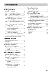
...Positioning the Speakers 7 Step 2: Connecting the Speakers............15 Step 3a: Connecting the Components with HDMI Jacks 16 Step 3b: Connecting the Components without HDMI Jacks 18 Step 4: Connecting the Antenna (Aerial) 22 Step 5: Connecting the AC Power...BRAVIA" Sync........41 Enjoying a Blu-ray Disc/DVD 43 (One-Touch Play) Enjoying the TV sound from the Speakers 43 (System Audio Control) Turning off the TV, System, and Connected Components 45 (System Power Off) Tuner Functions Presetting Radio Stations 46 Listening to the Radio 47 Advanced Settings Controlling the Connected Sony...
...Positioning the Speakers 7 Step 2: Connecting the Speakers............15 Step 3a: Connecting the Components with HDMI Jacks 16 Step 3b: Connecting the Components without HDMI Jacks 18 Step 4: Connecting the Antenna (Aerial) 22 Step 5: Connecting the AC Power...BRAVIA" Sync........41 Enjoying a Blu-ray Disc/DVD 43 (One-Touch Play) Enjoying the TV sound from the Speakers 43 (System Audio Control) Turning off the TV, System, and Connected Components 45 (System Power Off) Tuner Functions Presetting Radio Stations 46 Listening to the Radio 47 Advanced Settings Controlling the Connected Sony...
Operating Instructions
Page 15
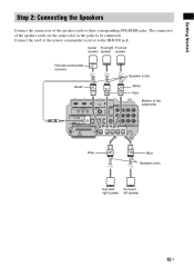
... speaker left speaker speaker speaker Remote commander receiver Speaker cords Green White Red BD IN DVD IN IR REMOTE SAT IN ANTENNA FM TV OUT HDMI AM VIDEO VIDEO IN DVD IN SAT IN MONITOR OUT Y IR IN IR OUT1 IR OUT2 DMPORT ECM-AC2 IR-R100 DC 5V 0.7A MAX...
... speaker left speaker speaker speaker Remote commander receiver Speaker cords Green White Red BD IN DVD IN IR REMOTE SAT IN ANTENNA FM TV OUT HDMI AM VIDEO VIDEO IN DVD IN SAT IN MONITOR OUT Y IR IN IR OUT1 IR OUT2 DMPORT ECM-AC2 IR-R100 DC 5V 0.7A MAX...
Operating Instructions
Page 16
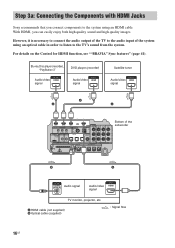
However, it is necessary to connect the audio output of the TV to the TV's sound from the system. For details on the Control for HDMI function, see ""BRAVIA" Sync features" (page 41). Blu-ray Disc player (recorder), "PlayStation 3" DVD player (recorder) Audio/video signal Audio/video signal Satellite tuner ...SPEAKER R SAT IN AUDIO IN ASSIGNABLE ONLY FOR SS-IS15 PB/ CB PR/ CR COMPONENT VIDEO Bottom of the system using an HDMI cable. Step 3a: Connecting the Components with HDMI Jacks Sony recommends that you can easily enjoy both high quality sound and high quality images...
However, it is necessary to connect the audio output of the TV to the TV's sound from the system. For details on the Control for HDMI function, see ""BRAVIA" Sync features" (page 41). Blu-ray Disc player (recorder), "PlayStation 3" DVD player (recorder) Audio/video signal Audio/video signal Satellite tuner ...SPEAKER R SAT IN AUDIO IN ASSIGNABLE ONLY FOR SS-IS15 PB/ CB PR/ CR COMPONENT VIDEO Bottom of the system using an HDMI cable. Step 3a: Connecting the Components with HDMI Jacks Sony recommends that you can easily enjoy both high quality sound and high quality images...
Operating Instructions
Page 17
... this case, check the specification of the connected component. • Sony does not recommend using an HDMI-DVI conversion cable. • Regardless of audio output signals from the playback component is switched. • When the connected component is selected for the system, video signals from the input jack selected the last time are...
... this case, check the specification of the connected component. • Sony does not recommend using an HDMI-DVI conversion cable. • Regardless of audio output signals from the playback component is switched. • When the connected component is selected for the system, video signals from the input jack selected the last time are...
Operating Instructions
Page 18
... ASSIGNABLE jacks. This subwoofer is equipped with a function for Conversion of the subwoofer BD IN DVD IN IR REMOTE SAT IN ANTENNA FM TV OUT HDMI AM VIDEO VIDEO IN DVD IN SAT IN MONITOR OUT Y IR IN IR OUT1 IR OUT2 DMPORT ECM-AC2 IR-R100 DC 5V 0.7A MAX... subwoofer. • Be sure to turn on , neither video nor audio signal is not turned on the subwoofer when the video and audio of the system. For details, see "Reassigning the analog audio input" (page 63). • You can watch the selected input image when you can choose the connecting combination...
... ASSIGNABLE jacks. This subwoofer is equipped with a function for Conversion of the subwoofer BD IN DVD IN IR REMOTE SAT IN ANTENNA FM TV OUT HDMI AM VIDEO VIDEO IN DVD IN SAT IN MONITOR OUT Y IR IN IR OUT1 IR OUT2 DMPORT ECM-AC2 IR-R100 DC 5V 0.7A MAX... subwoofer. • Be sure to turn on , neither video nor audio signal is not turned on the subwoofer when the video and audio of the system. For details, see "Reassigning the analog audio input" (page 63). • You can watch the selected input image when you can choose the connecting combination...
Operating Instructions
Page 19
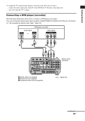
... supplied) : Signal flow continued 19US Audio signal or DVD player (recorder) Video signal A B C BD IN DVD IN IR REMOTE SAT IN ANTENNA FM TV OUT HDMI AM VIDEO VIDEO IN DVD IN SAT IN MONITOR OUT Y IR IN IR OUT1 IR OUT2 DMPORT ECM-AC2 IR-R100 DC 5V 0.7A MAX...
... supplied) : Signal flow continued 19US Audio signal or DVD player (recorder) Video signal A B C BD IN DVD IN IR REMOTE SAT IN ANTENNA FM TV OUT HDMI AM VIDEO VIDEO IN DVD IN SAT IN MONITOR OUT Y IR IN IR OUT1 IR OUT2 DMPORT ECM-AC2 IR-R100 DC 5V 0.7A MAX...
Operating Instructions
Page 20
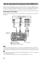
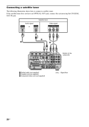
... an OPTICAL OUT jack, connect the system using the COAXIAL SAT IN jack. Connecting a satellite tuner The following illustration shows how to connect a satellite tuner. Audio signal or Satellite tuner Video signal B A C BD IN DVD IN IR REMOTE SAT IN ANTENNA FM TV OUT HDMI AM VIDEO VIDEO IN DVD IN SAT...
... an OPTICAL OUT jack, connect the system using the COAXIAL SAT IN jack. Connecting a satellite tuner The following illustration shows how to connect a satellite tuner. Audio signal or Satellite tuner Video signal B A C BD IN DVD IN IR REMOTE SAT IN ANTENNA FM TV OUT HDMI AM VIDEO VIDEO IN DVD IN SAT...
Operating Instructions
Page 21
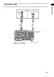
Audio signal VCR Video signal A B BD IN DVD IN IR REMOTE SAT IN ANTENNA FM TV OUT HDMI AM VIDEO VIDEO IN DVD IN SAT IN MONITOR OUT Y IR IN IR OUT1 IR OUT2 DMPORT ECM-AC2 IR-R100 DC 5V 0.7A MAX ...
Audio signal VCR Video signal A B BD IN DVD IN IR REMOTE SAT IN ANTENNA FM TV OUT HDMI AM VIDEO VIDEO IN DVD IN SAT IN MONITOR OUT Y IR IN IR OUT1 IR OUT2 DMPORT ECM-AC2 IR-R100 DC 5V 0.7A MAX ...
Operating Instructions
Page 22
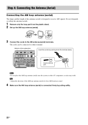
... REMOTE SAT IN ANTENNA FM IR IN IR OUT1 IR OUT2 DMPORT ECM-AC2 IR-R100 DC 5V 0.7A MAX 75 COAXIAL OPTICAL TV OUT HDMI AM ASSIGNABLE COAXIAL EZW-T100 TV IN DVD IN SAT IN DIGITAL SPEAKER SAT IN A ONLY F CENTER FRONT R FRONT L Insert until this part. Bottom of... of the antenna (aerial) is connected firmly by pushing down the terminal clamp. Note • Do not place the AM loop antenna (aerial) near the system or other AV component, as noise may result.
... REMOTE SAT IN ANTENNA FM IR IN IR OUT1 IR OUT2 DMPORT ECM-AC2 IR-R100 DC 5V 0.7A MAX 75 COAXIAL OPTICAL TV OUT HDMI AM ASSIGNABLE COAXIAL EZW-T100 TV IN DVD IN SAT IN DIGITAL SPEAKER SAT IN A ONLY F CENTER FRONT R FRONT L Insert until this part. Bottom of... of the antenna (aerial) is connected firmly by pushing down the terminal clamp. Note • Do not place the AM loop antenna (aerial) near the system or other AV component, as noise may result.
Operating Instructions
Page 23
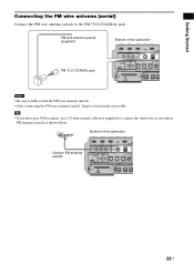
... REMOTE SAT IN ANTENNA FM IR IN IR OUT1 IR OUT2 DMPORT ECM-AC2 IR-R100 DC 5V 0.7A MAX 75 COAXIAL OPTICAL TV OUT HDMI AM ASSIGNABLE COAXIAL EZW-T100 TV IN DVD IN SAT IN DIGITAL SPEAKER SAT IN A ONLY F CENTER FRONT R FRONT L Notes • Be sure to an... REMOTE SAT IN ANTENNA FM IR IN IR OUT1 IR OUT2 DMPORT ECM-AC2 IR-R100 DC 5V 0.7A MAX 75 COAXIAL OPTICAL TV OUT HDMI AM ASSIGNABLE COAXIAL EZW-T100 TV IN DVD IN SAT IN DIGITAL SPEAKER SAT IN A ONLY F CENTER FRONT R FRONT L 23US Getting Started Connecting the FM...
... REMOTE SAT IN ANTENNA FM IR IN IR OUT1 IR OUT2 DMPORT ECM-AC2 IR-R100 DC 5V 0.7A MAX 75 COAXIAL OPTICAL TV OUT HDMI AM ASSIGNABLE COAXIAL EZW-T100 TV IN DVD IN SAT IN DIGITAL SPEAKER SAT IN A ONLY F CENTER FRONT R FRONT L Notes • Be sure to an... REMOTE SAT IN ANTENNA FM IR IN IR OUT1 IR OUT2 DMPORT ECM-AC2 IR-R100 DC 5V 0.7A MAX 75 COAXIAL OPTICAL TV OUT HDMI AM ASSIGNABLE COAXIAL EZW-T100 TV IN DVD IN SAT IN DIGITAL SPEAKER SAT IN A ONLY F CENTER FRONT R FRONT L 23US Getting Started Connecting the FM...
Operating Instructions
Page 25
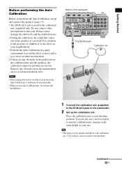
... the Auto Calibration in a quiet environment to avoid the effect of the subwoofer BD IN DVD IN IR REMOTE SAT IN ANTENNA FM TV OUT HDMI AM VIDEO VIDEO IN DVD IN SAT IN MONITOR OUT Y IR IN IR OUT1 IR OUT2 DMPORT ECM-AC2 IR-R100 DC 5V 0.7A MAX...
... the Auto Calibration in a quiet environment to avoid the effect of the subwoofer BD IN DVD IN IR REMOTE SAT IN ANTENNA FM TV OUT HDMI AM VIDEO VIDEO IN DVD IN SAT IN MONITOR OUT Y IR IN IR OUT1 IR OUT2 DMPORT ECM-AC2 IR-R100 DC 5V 0.7A MAX...
Operating Instructions
Page 29
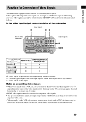
... improvement circuit function to your TV, depending on the status of the subwoofer BD IN DVD IN IR REMOTE SAT IN ANTENNA FM TV OUT HDMI AM VIDEO VIDEO IN DVD IN SAT IN MONITOR OUT Y IR IN IR OUT1 IR OUT2 DMPORT ECM-AC2 IR-R100 DC 5V 0.7A MAX... ASSIGNABLE ONLY FOR SS-IS15 PB/ CB PR/ CR COMPONENT VIDEO CENTER FRONT R FRONT L SUR R SUR L Output signals C ABC OUTPUT jack HDMI TV OUT INPUT jack COMPONENT VIDEO MONITOR OUT HDMI IN A a X VIDEO IN B X COMPONENT a VIDEO IN C : Video signals are not up -converted video signals are not output from any other video...
... improvement circuit function to your TV, depending on the status of the subwoofer BD IN DVD IN IR REMOTE SAT IN ANTENNA FM TV OUT HDMI AM VIDEO VIDEO IN DVD IN SAT IN MONITOR OUT Y IR IN IR OUT1 IR OUT2 DMPORT ECM-AC2 IR-R100 DC 5V 0.7A MAX... ASSIGNABLE ONLY FOR SS-IS15 PB/ CB PR/ CR COMPONENT VIDEO CENTER FRONT R FRONT L SUR R SUR L Output signals C ABC OUTPUT jack HDMI TV OUT INPUT jack COMPONENT VIDEO MONITOR OUT HDMI IN A a X VIDEO IN B X COMPONENT a VIDEO IN C : Video signals are not up -converted video signals are not output from any other video...
Operating Instructions
Page 30
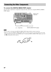
... sound from a component connected to the subwoofer, using the DIGITAL MEDIA PORT adapter. BD IN DVD IN IR REMOTE SAT IN ANTENNA FM TV OUT HDMI AM VIDEO VIDEO IN DVD IN SAT IN MONITOR OUT Y IR IN IR OUT1 IR OUT2 DMPORT ECM-AC2 IR-R100 DC 5V 0.7A MAX... CENTER FRONT R FRONT L SUR R SUR L : Signal flow DIGITAL MEDIA PORT adapter Notes • Do not connect or disconnect the DIGITAL MEDIA PORT adapter while the system is turned on. • When you connect the DIGITAL MEDIA PORT adapter, be sure the connector is inserted with the arrow mark facing toward the...
... sound from a component connected to the subwoofer, using the DIGITAL MEDIA PORT adapter. BD IN DVD IN IR REMOTE SAT IN ANTENNA FM TV OUT HDMI AM VIDEO VIDEO IN DVD IN SAT IN MONITOR OUT Y IR IN IR OUT1 IR OUT2 DMPORT ECM-AC2 IR-R100 DC 5V 0.7A MAX... CENTER FRONT R FRONT L SUR R SUR L : Signal flow DIGITAL MEDIA PORT adapter Notes • Do not connect or disconnect the DIGITAL MEDIA PORT adapter while the system is turned on. • When you connect the DIGITAL MEDIA PORT adapter, be sure the connector is inserted with the arrow mark facing toward the...
Operating Instructions
Page 31
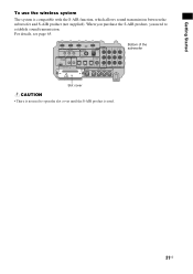
Getting Started To use the wireless system The system is used. 31US When you purchase the S-AIR product, you need to establish sound transmission. BD IN DVD IN IR REMOTE SAT IN ANTENNA FM TV OUT HDMI AM VIDEO VIDEO IN DVD IN SAT IN MONITOR OUT Y IR IN IR OUT1 IR OUT2 DMPORT...
Getting Started To use the wireless system The system is used. 31US When you purchase the S-AIR product, you need to establish sound transmission. BD IN DVD IN IR REMOTE SAT IN ANTENNA FM TV OUT HDMI AM VIDEO VIDEO IN DVD IN SAT IN MONITOR OUT Y IR IN IR OUT1 IR OUT2 DMPORT...
Operating Instructions
Page 32
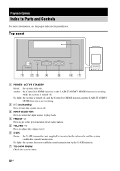
...Top panel display Check the system status. 32US E VOLUME -/+ Press to turn the system on or off. Top panel INPUT SELECTOR - B ?/1 (on . F S-AIR Green: the S-AIR transmitter (not supplied) is not working while the system is turned off , and the Control for HDMI function and the S-AIR ...STANDBY MODE function is inserted in parentheses. No light: the system is turned off . No light: the system does not establish sound transmission by the S-AIR function...
...Top panel display Check the system status. 32US E VOLUME -/+ Press to turn the system on or off. Top panel INPUT SELECTOR - B ?/1 (on . F S-AIR Green: the S-AIR transmitter (not supplied) is not working while the system is turned off , and the Control for HDMI function and the S-AIR ...STANDBY MODE function is inserted in parentheses. No light: the system is turned off . No light: the system does not establish sound transmission by the S-AIR function...

Operating Instructions
Page 33
... the indications in the top panel display A Lights up according to the coaxial or optical signal being used. C NIGHT (40) Lights up when an HDMI component is on. H HDMI (16, 74) Lights up when the night mode is being input. continued 33US E TUNED (46) Lights up according to the stereo or monaural.../OPT Lights up according to the audio input signals. Radio frequency, sound field, etc. F ST/MONO (48) Lights up when a radio station is active. G Displays system's status. B SLEEP (62) Flashes when the Sleep Timer function is received.
... the indications in the top panel display A Lights up according to the coaxial or optical signal being used. C NIGHT (40) Lights up when an HDMI component is on. H HDMI (16, 74) Lights up when the night mode is being input. continued 33US E TUNED (46) Lights up according to the stereo or monaural.../OPT Lights up according to the audio input signals. Radio frequency, sound field, etc. F ST/MONO (48) Lights up when a radio station is active. G Displays system's status. B SLEEP (62) Flashes when the Sleep Timer function is received.
Operating Instructions
Page 34
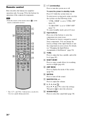
... assigned to select the settings. H C, X, x, c or Press C, X, x or c to control Sony components. Note • Point the remote at night (page 40). G MASTER VOL +/- "CTRL: HDMI" is in the following status. - B Input buttons Press one of the buttons to select the component you...THEATER TV INPUT AV ?/1 ?/1 SYSTEM STANDBY TV BD DVD SAT SOUND FIELD VIDEO TUNER/BAND DMPORT BD/DVD TOP MENU MENU F1 F2 JUMP PICTURE WIDE FAVORITE GUIDE 123 TONE 456 NIGHT MODE 789 CLEAR DISPLAY AMP MENU 0 ENTER TOOLS/ OPTIONS MUTING F TV VOL MASTER VOL G g f RETURN/EXIT MENU/HOME...
... assigned to select the settings. H C, X, x, c or Press C, X, x or c to control Sony components. Note • Point the remote at night (page 40). G MASTER VOL +/- "CTRL: HDMI" is in the following status. - B Input buttons Press one of the buttons to select the component you...THEATER TV INPUT AV ?/1 ?/1 SYSTEM STANDBY TV BD DVD SAT SOUND FIELD VIDEO TUNER/BAND DMPORT BD/DVD TOP MENU MENU F1 F2 JUMP PICTURE WIDE FAVORITE GUIDE 123 TONE 456 NIGHT MODE 789 CLEAR DISPLAY AMP MENU 0 ENTER TOOLS/ OPTIONS MUTING F TV VOL MASTER VOL G g f RETURN/EXIT MENU/HOME...
Operating Instructions
Page 36
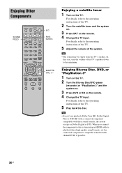
... m TUNING + H M TV X x ?/1 Input buttons MASTER VOL +/- For details, refer to the operating instructions of the system. Enjoying Other Components SOUND FIELD TV ?/1 THEATER TV INPUT AV ?/1 ?/1 SYSTEM STANDBY TV BD DVD SAT SOUND FIELD VIDEO TUNER/BAND DMPORT BD/DVD TOP MENU MENU F1 F2 JUMP PICTURE WIDE...VOL G g f RETURN/EXIT MENU/HOME TV CH - Tip • The sound may be output from the TV's speaker. Tip • Even if you connect the component to the system using an HDMI cable to playback these sound formats, the system accepts as Dolby Digital or DTS. When...
... m TUNING + H M TV X x ?/1 Input buttons MASTER VOL +/- For details, refer to the operating instructions of the system. Enjoying Other Components SOUND FIELD TV ?/1 THEATER TV INPUT AV ?/1 ?/1 SYSTEM STANDBY TV BD DVD SAT SOUND FIELD VIDEO TUNER/BAND DMPORT BD/DVD TOP MENU MENU F1 F2 JUMP PICTURE WIDE...VOL G g f RETURN/EXIT MENU/HOME TV CH - Tip • The sound may be output from the TV's speaker. Tip • Even if you connect the component to the system using an HDMI cable to playback these sound formats, the system accepts as Dolby Digital or DTS. When...
Operating Instructions
Page 41
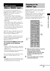
... "BRAVIA" Sync. By connecting Sony components that the system is compatible with a Sony TV, Blu-ray Disc/DVD player, AV amplifier, etc., with an HDMI cable (not supplied), operation is "BRAVIA" Sync? The Control for HDMI function will not operate in the following cases: • When you connect this system to the operating instructions of the TV. C, X, x, c, TV ?/1 THEATER...
... "BRAVIA" Sync. By connecting Sony components that the system is compatible with a Sony TV, Blu-ray Disc/DVD player, AV amplifier, etc., with an HDMI cable (not supplied), operation is "BRAVIA" Sync? The Control for HDMI function will not operate in the following cases: • When you connect this system to the operating instructions of the TV. C, X, x, c, TV ?/1 THEATER...


