Operating Instructions
Page 5
... for the "BRAVIA" Sync........41 Enjoying a Blu-ray Disc/DVD 43 (One-Touch Play) Enjoying the TV sound from the Speakers 43 (System Audio Control) Turning off the TV, System, and Connected Components 45 (System Power Off) Tuner Functions Presetting Radio Stations 46 Listening to the Radio 47 Advanced Settings Controlling the Connected Sony Components with...
... for the "BRAVIA" Sync........41 Enjoying a Blu-ray Disc/DVD 43 (One-Touch Play) Enjoying the TV sound from the Speakers 43 (System Audio Control) Turning off the TV, System, and Connected Components 45 (System Power Off) Tuner Functions Presetting Radio Stations 46 Listening to the Radio 47 Advanced Settings Controlling the Connected Sony Components with...
Operating Instructions
Page 6
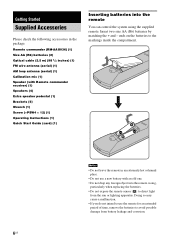
...1/2 inches) (1) FM wire antenna (aerial) (1) AM loop antenna (aerial) (1) Calibration mic (1) Speaker (with an old one. • Do not drop any foreign object into the remote You can control the system using the supplied remote. Doing so may cause a malfunction. • If you do not intend... to use a new battery with Remote commander receiver) (1) Speakers (4) Extra speaker pedestal (1) Brackets (5) Wrench (1) Screw (+PSW4 × 12...
...1/2 inches) (1) FM wire antenna (aerial) (1) AM loop antenna (aerial) (1) Calibration mic (1) Speaker (with an old one. • Do not drop any foreign object into the remote You can control the system using the supplied remote. Doing so may cause a malfunction. • If you do not intend... to use a new battery with Remote commander receiver) (1) Speakers (4) Extra speaker pedestal (1) Brackets (5) Wrench (1) Screw (+PSW4 × 12...
Operating Instructions
Page 7
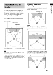
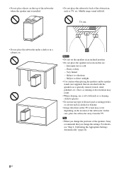
...clamper or a commercially available tape, etc., to secure the speaker cord. • You may be placed at the same ... speaker, the distance should be less than the subwoofer should be placed (2). Front left speaker Surround right speaker Tips... • You can also place the subwoofer either side, facing the listening position. • When you install the speaker, the speaker...Speakers For the best possible surround sound, all the speakers other than 0.5 m (1.6 ft).* * 111 1 1 Surround left speaker Center speaker Subwoofer 2 Front right speaker...
...clamper or a commercially available tape, etc., to secure the speaker cord. • You may be placed at the same ... speaker, the distance should be less than the subwoofer should be placed (2). Front left speaker Surround right speaker Tips... • You can also place the subwoofer either side, facing the listening position. • When you install the speaker, the speaker...Speakers For the best possible surround sound, all the speakers other than 0.5 m (1.6 ft).* * 111 1 1 Surround left speaker Center speaker Subwoofer 2 Front right speaker...
Operating Instructions
Page 8
... the subwoofer away from the TV. Notes • Do not set the speakers in an inclined position. • Do not place the speakers in a cabinet, etc. Tip • When you change the positions of the speakers, Sony recommends that are attached with the speakers on a specially treated (waxed, oiled, polished, etc.) floor, as staining or...
... the subwoofer away from the TV. Notes • Do not set the speakers in an inclined position. • Do not place the speakers in a cabinet, etc. Tip • When you change the positions of the speakers, Sony recommends that are attached with the speakers on a specially treated (waxed, oiled, polished, etc.) floor, as staining or...
Operating Instructions
Page 9
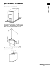
Slits • Do not push the top of the subwoofer when lifting it. Getting Started Notes on handling the subwoofer • Place a soft cloth under the subwoofer when you lay the subwoofer down for connection. • Do not place your hand into the slit of the subwoofer where the speaker unit is installed. When lifting, hold the bottom of the subwoofer. Speaker unit continued 9US The speaker driver may be damaged.
Slits • Do not push the top of the subwoofer when lifting it. Getting Started Notes on handling the subwoofer • Place a soft cloth under the subwoofer when you lay the subwoofer down for connection. • Do not place your hand into the slit of the subwoofer where the speaker unit is installed. When lifting, hold the bottom of the subwoofer. Speaker unit continued 9US The speaker driver may be damaged.
Operating Instructions
Page 10
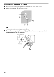
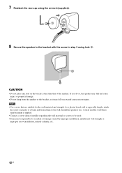
Wrench (supplied) Rear cap 10US Installing the speakers on a wall 1 Prepare screws (not supplied) that are suitable for the holes of the bracket. 2 Secure the bracket to the wall using hole 1. 1 2 34 Tip • To prevent the speaker from rotating, use the hole 2, too. 3 Remove the rear cap using the wrench (supplied), and remove the speaker pedestal using a screwdriver (+) (not supplied).
Wrench (supplied) Rear cap 10US Installing the speakers on a wall 1 Prepare screws (not supplied) that are suitable for the holes of the bracket. 2 Secure the bracket to the wall using hole 1. 1 2 34 Tip • To prevent the speaker from rotating, use the hole 2, too. 3 Remove the rear cap using the wrench (supplied), and remove the speaker pedestal using a screwdriver (+) (not supplied).
Operating Instructions
Page 11
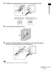
continued 11US speaker cords can be removed. 5 Thread the speaker cords through hole 3. 3 6 Reconnect the detached speaker cords, matching 3/# to the appropriate speaker terminals (1), and then push the lever down , use the wrench (supplied). Getting Started 4 Push A with the supplied wrench (1), and then remove the speaker cords (2). (2) (1) A When the lever is down, the When the lever is difficult to push the lever down completely (2). (2) (1) 3 # Tip • If it is up, the speaker cords are locked.
continued 11US speaker cords can be removed. 5 Thread the speaker cords through hole 3. 3 6 Reconnect the detached speaker cords, matching 3/# to the appropriate speaker terminals (1), and then push the lever down , use the wrench (supplied). Getting Started 4 Push A with the supplied wrench (1), and then remove the speaker cords (2). (2) (1) A When the lever is down, the When the lever is difficult to push the lever down completely (2). (2) (1) 3 # Tip • If it is up, the speaker cords are locked.
Operating Instructions
Page 12
Install the speakers on a vertical and flat wall where reinforcement is applied. • Contact a screw shop or installer regarding the wall material or screws to be used. • Sony is especially fragile, attach the screws securely to a beam and fasten them to the bracket with the screw in step 3 using hole 4. ...4 CAUTION • Do not place any load on you and cause serious injury. If you do so, the speaker may fall and cause ...
Install the speakers on a vertical and flat wall where reinforcement is applied. • Contact a screw shop or installer regarding the wall material or screws to be used. • Sony is especially fragile, attach the screws securely to a beam and fasten them to the bracket with the screw in step 3 using hole 4. ...4 CAUTION • Do not place any load on you and cause serious injury. If you do so, the speaker may fall and cause ...

Operating Instructions
Page 13
... a wall. 1 Remove the remote commander receiver using a screwdriver (+) (not supplied). 2 Secure the speaker with the screw. Getting Started About the center speaker You can also install the remote commander receiver with the center speaker on a wall. To use the center speaker and remote commander receiver separately. You can remove the remote commander receiver from...
... a wall. 1 Remove the remote commander receiver using a screwdriver (+) (not supplied). 2 Secure the speaker with the screw. Getting Started About the center speaker You can also install the remote commander receiver with the center speaker on a wall. To use the center speaker and remote commander receiver separately. You can remove the remote commander receiver from...
Operating Instructions
Page 14
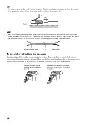
.... If the cords are touching each speaker cord does not touch another speaker cord, such as shown below. Stripped cords are reversed, the sound will lack bass and may damage the system. White letters or lines # Black tube To avoid short-circuiting the speakers Short-circuiting of another speaker terminal or the bare wire of...
.... If the cords are touching each speaker cord does not touch another speaker cord, such as shown below. Stripped cords are reversed, the sound will lack bass and may damage the system. White letters or lines # Black tube To avoid short-circuiting the speakers Short-circuiting of another speaker terminal or the bare wire of...
Operating Instructions
Page 15
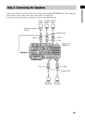
... the remote commander receiver to be connected. Getting Started Step 2: Connecting the Speakers Connect the connectors of the subwoofer CENTER FRONT R FRONT L SUR R SUR L Gray Blue Speaker cords Surround Surround right speaker left speaker speaker speaker Remote commander receiver Speaker cords Green White Red BD IN DVD IN IR REMOTE SAT IN ANTENNA FM... ECM-AC2 IR-R100 DC 5V 0.7A MAX EZW-T100 75 COAXIAL OPTICAL ASSIGNABLE L COAXIAL TV IN DVD IN SAT IN DIGITAL SPEAKER R SAT IN AUDIO IN ASSIGNABLE ONLY FOR SS-IS15 PB/ CB PR/ CR COMPONENT VIDEO Bottom of the...
... the remote commander receiver to be connected. Getting Started Step 2: Connecting the Speakers Connect the connectors of the subwoofer CENTER FRONT R FRONT L SUR R SUR L Gray Blue Speaker cords Surround Surround right speaker left speaker speaker speaker Remote commander receiver Speaker cords Green White Red BD IN DVD IN IR REMOTE SAT IN ANTENNA FM... ECM-AC2 IR-R100 DC 5V 0.7A MAX EZW-T100 75 COAXIAL OPTICAL ASSIGNABLE L COAXIAL TV IN DVD IN SAT IN DIGITAL SPEAKER R SAT IN AUDIO IN ASSIGNABLE ONLY FOR SS-IS15 PB/ CB PR/ CR COMPONENT VIDEO Bottom of the...
Operating Instructions
Page 16
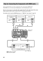
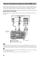
... you connect components to the TV's sound from the system. Step 3a: Connecting the Components with HDMI Jacks Sony recommends that you can easily enjoy both high quality sound ...R SUR L B A Audio signal Audio/video signal TV monitor, projector, etc. For details on the Control for HDMI function, see ""BRAVIA" Sync features" (page 41). A HDMI cable (not supplied) B Optical cable (supplied) : Signal flow 16US Blu-ray Disc player...ASSIGNABLE L COAXIAL TV IN DVD IN SAT IN DIGITAL SPEAKER R SAT IN AUDIO IN ASSIGNABLE ONLY FOR SS-IS15 PB/ CB PR/ CR COMPONENT VIDEO Bottom...
... you connect components to the TV's sound from the system. Step 3a: Connecting the Components with HDMI Jacks Sony recommends that you can easily enjoy both high quality sound ...R SUR L B A Audio signal Audio/video signal TV monitor, projector, etc. For details on the Control for HDMI function, see ""BRAVIA" Sync features" (page 41). A HDMI cable (not supplied) B Optical cable (supplied) : Signal flow 16US Blu-ray Disc player...ASSIGNABLE L COAXIAL TV IN DVD IN SAT IN DIGITAL SPEAKER R SAT IN AUDIO IN ASSIGNABLE ONLY FOR SS-IS15 PB/ CB PR/ CR COMPONENT VIDEO Bottom...
Operating Instructions
Page 18
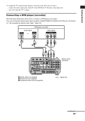
... IR OUT2 DMPORT ECM-AC2 IR-R100 DC 5V 0.7A MAX EZW-T100 75 COAXIAL OPTICAL ASSIGNABLE L COAXIAL TV IN DVD IN SAT IN DIGITAL SPEAKER R SAT IN AUDIO IN ASSIGNABLE ONLY FOR SS-IS15 PB/ CB PR/ CR COMPONENT VIDEO CENTER FRONT R FRONT L SUR R SUR L A Optical cable (supplied) ...the selected input image when you connect the MONITOR OUT jack to a TV. 18US Audio signal or Video signal INPUT A B C Bottom of the system. For details, see "Function for converting video signals. Tips • You can be displayed on the subwoofer when the video and audio of Video ...
... IR OUT2 DMPORT ECM-AC2 IR-R100 DC 5V 0.7A MAX EZW-T100 75 COAXIAL OPTICAL ASSIGNABLE L COAXIAL TV IN DVD IN SAT IN DIGITAL SPEAKER R SAT IN AUDIO IN ASSIGNABLE ONLY FOR SS-IS15 PB/ CB PR/ CR COMPONENT VIDEO CENTER FRONT R FRONT L SUR R SUR L A Optical cable (supplied) ...the selected input image when you connect the MONITOR OUT jack to a TV. 18US Audio signal or Video signal INPUT A B C Bottom of the system. For details, see "Function for converting video signals. Tips • You can be displayed on the subwoofer when the video and audio of Video ...
Operating Instructions
Page 19
... IR OUT2 DMPORT ECM-AC2 IR-R100 DC 5V 0.7A MAX EZW-T100 75 COAXIAL OPTICAL ASSIGNABLE L COAXIAL TV IN DVD IN SAT IN DIGITAL SPEAKER R SAT IN AUDIO IN ASSIGNABLE ONLY FOR SS-IS15 PB/ CB PR/ CR COMPONENT VIDEO Bottom of the subwoofer. - turn off or mute the TV...
... IR OUT2 DMPORT ECM-AC2 IR-R100 DC 5V 0.7A MAX EZW-T100 75 COAXIAL OPTICAL ASSIGNABLE L COAXIAL TV IN DVD IN SAT IN DIGITAL SPEAKER R SAT IN AUDIO IN ASSIGNABLE ONLY FOR SS-IS15 PB/ CB PR/ CR COMPONENT VIDEO Bottom of the subwoofer. - turn off or mute the TV...
Operating Instructions
Page 20
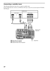
If the satellite tuner does not have an OPTICAL OUT jack, connect the system using the COAXIAL SAT IN jack. Audio signal or Satellite tuner Video signal B A C BD IN DVD IN IR REMOTE SAT IN ANTENNA FM TV OUT ... IR OUT2 DMPORT ECM-AC2 IR-R100 DC 5V 0.7A MAX EZW-T100 75 COAXIAL OPTICAL ASSIGNABLE L COAXIAL TV IN DVD IN SAT IN DIGITAL SPEAKER R SAT IN AUDIO IN ASSIGNABLE ONLY FOR SS-IS15 PB/ CB PR/ CR COMPONENT VIDEO Bottom of the subwoofer CENTER FRONT R FRONT L SUR R SUR L A Optical...
If the satellite tuner does not have an OPTICAL OUT jack, connect the system using the COAXIAL SAT IN jack. Audio signal or Satellite tuner Video signal B A C BD IN DVD IN IR REMOTE SAT IN ANTENNA FM TV OUT ... IR OUT2 DMPORT ECM-AC2 IR-R100 DC 5V 0.7A MAX EZW-T100 75 COAXIAL OPTICAL ASSIGNABLE L COAXIAL TV IN DVD IN SAT IN DIGITAL SPEAKER R SAT IN AUDIO IN ASSIGNABLE ONLY FOR SS-IS15 PB/ CB PR/ CR COMPONENT VIDEO Bottom of the subwoofer CENTER FRONT R FRONT L SUR R SUR L A Optical...
Operating Instructions
Page 21
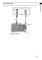
... IR OUT2 DMPORT ECM-AC2 IR-R100 DC 5V 0.7A MAX EZW-T100 75 COAXIAL OPTICAL ASSIGNABLE L COAXIAL TV IN DVD IN SAT IN DIGITAL SPEAKER R SAT IN AUDIO IN ASSIGNABLE ONLY FOR SS-IS15 PB/ CB PR/ CR COMPONENT VIDEO Bottom of the subwoofer CENTER FRONT R FRONT L SUR R SUR L A Audio...
... IR OUT2 DMPORT ECM-AC2 IR-R100 DC 5V 0.7A MAX EZW-T100 75 COAXIAL OPTICAL ASSIGNABLE L COAXIAL TV IN DVD IN SAT IN DIGITAL SPEAKER R SAT IN AUDIO IN ASSIGNABLE ONLY FOR SS-IS15 PB/ CB PR/ CR COMPONENT VIDEO Bottom of the subwoofer CENTER FRONT R FRONT L SUR R SUR L A Audio...
Operating Instructions
Page 22
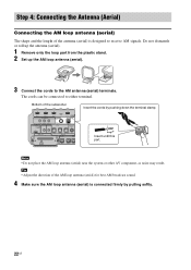
... up the AM loop antenna (aerial). 3 Connect the cords to receive AM signals. Note • Do not place the AM loop antenna (aerial) near the system or other AV component, as noise may result. Bottom of the AM loop antenna (aerial) for best AM broadcast sound. 4 Make sure the AM loop...-AC2 IR-R100 DC 5V 0.7A MAX 75 COAXIAL OPTICAL TV OUT HDMI AM ASSIGNABLE COAXIAL EZW-T100 TV IN DVD IN SAT IN DIGITAL SPEAKER SAT IN A ONLY F CENTER FRONT R FRONT L Insert until this part. The cords can be connected to either terminal.
... up the AM loop antenna (aerial). 3 Connect the cords to receive AM signals. Note • Do not place the AM loop antenna (aerial) near the system or other AV component, as noise may result. Bottom of the AM loop antenna (aerial) for best AM broadcast sound. 4 Make sure the AM loop...-AC2 IR-R100 DC 5V 0.7A MAX 75 COAXIAL OPTICAL TV OUT HDMI AM ASSIGNABLE COAXIAL EZW-T100 TV IN DVD IN SAT IN DIGITAL SPEAKER SAT IN A ONLY F CENTER FRONT R FRONT L Insert until this part. The cords can be connected to either terminal.
Operating Instructions
Page 23
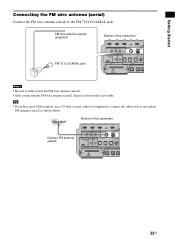
...-AC2 IR-R100 DC 5V 0.7A MAX 75 COAXIAL OPTICAL TV OUT HDMI AM ASSIGNABLE COAXIAL EZW-T100 TV IN DVD IN SAT IN DIGITAL SPEAKER SAT IN A ONLY F CENTER FRONT R FRONT L 23US Bottom of the subwoofer BD IN DVD IN IR REMOTE SAT IN ANTENNA FM IR IN IR OUT1...-AC2 IR-R100 DC 5V 0.7A MAX 75 COAXIAL OPTICAL TV OUT HDMI AM ASSIGNABLE COAXIAL EZW-T100 TV IN DVD IN SAT IN DIGITAL SPEAKER SAT IN A ONLY F CENTER FRONT R FRONT L Notes • Be sure to the FM 75 Ω COAXIAL jack. Getting Started Connecting the FM wire antenna (aerial...
...-AC2 IR-R100 DC 5V 0.7A MAX 75 COAXIAL OPTICAL TV OUT HDMI AM ASSIGNABLE COAXIAL EZW-T100 TV IN DVD IN SAT IN DIGITAL SPEAKER SAT IN A ONLY F CENTER FRONT R FRONT L 23US Bottom of the subwoofer BD IN DVD IN IR REMOTE SAT IN ANTENNA FM IR IN IR OUT1...-AC2 IR-R100 DC 5V 0.7A MAX 75 COAXIAL OPTICAL TV OUT HDMI AM ASSIGNABLE COAXIAL EZW-T100 TV IN DVD IN SAT IN DIGITAL SPEAKER SAT IN A ONLY F CENTER FRONT R FRONT L Notes • Be sure to the FM 75 Ω COAXIAL jack. Getting Started Connecting the FM wire antenna (aerial...
Operating Instructions
Page 24
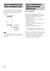
.... • Measure the distance of more than 96 kHz. However, you to your room. For details, see "Setting the speaker level" (page 57). 24US Step 5: Connecting the AC Power Cord (Mains Lead) Before connecting the AC power cord (mains lead) of the... lead), wait about 20 seconds before turning on the power by pressing "/1. Rear of the subwoofer to a wall outlet (mains), connect all the speakers to obtain proper sound balance in your preference. The D.C.A.C. Step 6: Calibrating the Appropriate Settings Automatically (Auto Calibration) This subwoofer is equipped with a sampling...
.... • Measure the distance of more than 96 kHz. However, you to your room. For details, see "Setting the speaker level" (page 57). 24US Step 5: Connecting the AC Power Cord (Mains Lead) Before connecting the AC power cord (mains lead) of the... lead), wait about 20 seconds before turning on the power by pressing "/1. Rear of the subwoofer to a wall outlet (mains), connect all the speakers to obtain proper sound balance in your preference. The D.C.A.C. Step 6: Calibrating the Appropriate Settings Automatically (Auto Calibration) This subwoofer is equipped with a sampling...
Operating Instructions
Page 25
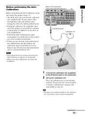
... IR OUT2 DMPORT ECM-AC2 IR-R100 DC 5V 0.7A MAX 75 COAXIAL OPTICAL ASSIGNABLE L COAXIAL R EZW-T100 TV IN DVD IN SAT IN DIGITAL SPEAKER SAT IN AUDIO IN ASSIGNABLE ONLY FOR SS-IS15 PB/ CB PR/ CR COMPONENT VIDEO CENTER FRONT R FRONT L SUR R SUR L To ECM-AC2 jack ... at your listening position. continued 25US Getting Started Before performing the Auto Calibration Before you use a stool or tripod so that comes out of the speakers is used for the calibration mic (supplied) only. Notes • If the muting function is on your ears. Place the calibration mic at the ...
... IR OUT2 DMPORT ECM-AC2 IR-R100 DC 5V 0.7A MAX 75 COAXIAL OPTICAL ASSIGNABLE L COAXIAL R EZW-T100 TV IN DVD IN SAT IN DIGITAL SPEAKER SAT IN AUDIO IN ASSIGNABLE ONLY FOR SS-IS15 PB/ CB PR/ CR COMPONENT VIDEO CENTER FRONT R FRONT L SUR R SUR L To ECM-AC2 jack ... at your listening position. continued 25US Getting Started Before performing the Auto Calibration Before you use a stool or tripod so that comes out of the speakers is used for the calibration mic (supplied) only. Notes • If the muting function is on your ears. Place the calibration mic at the ...


