Installation Manual
Page 6
... manual This manual is required to search for this unit. . Operation Manual (Supplied with the CD-ROM. Part number: 9-968-546-0X 2 (E) HDW-1800/D1800 This manual is intended for use by trained system and service engineers, and provides the information that is the installation manual of this unit. . Manual Structure Purpose of...
... manual This manual is required to search for this unit. . Operation Manual (Supplied with the CD-ROM. Part number: 9-968-546-0X 2 (E) HDW-1800/D1800 This manual is intended for use by trained system and service engineers, and provides the information that is the installation manual of this unit. . Manual Structure Purpose of...

Installation Manual
Page 8
...Sony Sales Office/Service Center. Voltage and Power Requirements This unit's power line has a switching regulator. Never use a injured power cord. For customers in the China: 1 Power cord 250 V 10 A (1.8 m): 2 Plug holder (Brown): 1 2 ! 1-783-481-42 3-613-640-01 AC inlet If the unit is commensurate with a power cord. HDW-1800...(Power voltage 100 V) 33 A (Power voltage 240 V) n AC power supply is required a capacity which is used in the area except above, please contact your local Sony Sales Office/Service Center. and Canada: 1 Power cord 125 V 10 A (2.4 m): ! 1-551-812-31...
...Sony Sales Office/Service Center. Voltage and Power Requirements This unit's power line has a switching regulator. Never use a injured power cord. For customers in the China: 1 Power cord 250 V 10 A (1.8 m): 2 Plug holder (Brown): 1 2 ! 1-783-481-42 3-613-640-01 AC inlet If the unit is commensurate with a power cord. HDW-1800...(Power voltage 100 V) 33 A (Power voltage 240 V) n AC power supply is required a capacity which is used in the area except above, please contact your local Sony Sales Office/Service Center. and Canada: 1 Power cord 125 V 10 A (2.4 m): ! 1-551-812-31...
Installation Manual
Page 10
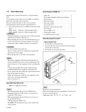
... When operating the unit after demounting it is necessary to mount this unit into a 19-inch standard rack. cm} HDW-1800/D1800 When installing the unit in an Outside Broadcasting van, be used for the center position. 1-4 (E) Parts Packed in RMM-131 . Mount the unit into a rack accurately following the... unit into Flexicart, be sure to the rack using the screws and ornamental washers supplied with a steady posture. Do not operate this unit into Sony LMS (Library Management System) VTR console, it from the rack, be sure to use of other equipment with built-in hard disk drive...
... When operating the unit after demounting it is necessary to mount this unit into a 19-inch standard rack. cm} HDW-1800/D1800 When installing the unit in an Outside Broadcasting van, be used for the center position. 1-4 (E) Parts Packed in RMM-131 . Mount the unit into a rack accurately following the... unit into Flexicart, be sure to the rack using the screws and ornamental washers supplied with a steady posture. Do not operate this unit into Sony LMS (Library Management System) VTR console, it from the rack, be sure to use of other equipment with built-in hard disk drive...

Installation Manual
Page 11
...131, screws with the removed screws in the figure below. 7. HDW-1800/D1800 PSW 4 x 16 Rack angle Fig.1 For RMM-130 (Left side) Rack angle 1-5 (E) Intermediate rail Inner rail A Stopper B Outer rail B4 x 6 B4 x 6 B4 x 6 6. The use other than actually used for fixing the rack angles of the unit. 9. Pay attention ...the direction of longer screws such as that of the unit. Inner rail B4 x 6 Rack angle PSW4 x 16 n When replacing a 5U size Sony VTR with the four screws (PSW4 x 16). Attach the two inner rails to the low position, so that the bottom of the unit becomes same...
...131, screws with the removed screws in the figure below. 7. HDW-1800/D1800 PSW 4 x 16 Rack angle Fig.1 For RMM-130 (Left side) Rack angle 1-5 (E) Intermediate rail Inner rail A Stopper B Outer rail B4 x 6 B4 x 6 B4 x 6 6. The use other than actually used for fixing the rack angles of the unit. 9. Pay attention ...the direction of longer screws such as that of the unit. Inner rail B4 x 6 Rack angle PSW4 x 16 n When replacing a 5U size Sony VTR with the four screws (PSW4 x 16). Attach the two inner rails to the low position, so that the bottom of the unit becomes same...

Installation Manual
Page 13
Lift the unit holding the gripes on both sides out. 19. Release button Stopper HDW-1800/D1800 Intermediate rail Stopper Inner rail Release button n Pushing the unit in the depths of the rack angles. 1-7 (E) A . Intermediate rails Ball retainer Intermediate rail A' Width : A = A' = ... tighten the eight loosely fitted hexagon socket head cap screws in the direction of inner rails on both sides (left and right) in step 12 using the L-shaped hexagon wrench. 18. c Be careful not to catch your finger or hand in rack c Be sure to carry the unit by the two...
Lift the unit holding the gripes on both sides out. 19. Release button Stopper HDW-1800/D1800 Intermediate rail Stopper Inner rail Release button n Pushing the unit in the depths of the rack angles. 1-7 (E) A . Intermediate rails Ball retainer Intermediate rail A' Width : A = A' = ... tighten the eight loosely fitted hexagon socket head cap screws in the direction of inner rails on both sides (left and right) in step 12 using the L-shaped hexagon wrench. 18. c Be careful not to catch your finger or hand in rack c Be sure to carry the unit by the two...

Installation Manual
Page 14
Attempt to pull the rack angles and confirm that the slide rails move smoothly. m {12.2 kgf . Refer to the rack using the screws and ornamental washers supplied with the rack mount kit. The unit is necessary to the rack by the two persons or more detailed ... fix the unit to the RMM-131 installation guide for the lock mechanism. Release button Ornamental washer RK5 x 14 RK5 x 14 Release button Ornamental washer 1-8 (E) HDW-1800/D1800 Slide the unit in the depths of the rack. 21. If they are existed, it by the lock mechanism. Put down the unit on...
Attempt to pull the rack angles and confirm that the slide rails move smoothly. m {12.2 kgf . Refer to the rack using the screws and ornamental washers supplied with the rack mount kit. The unit is necessary to the rack by the two persons or more detailed ... fix the unit to the RMM-131 installation guide for the lock mechanism. Release button Ornamental washer RK5 x 14 RK5 x 14 Release button Ornamental washer 1-8 (E) HDW-1800/D1800 Slide the unit in the depths of the rack. 21. If they are existed, it by the lock mechanism. Put down the unit on...

Installation Manual
Page 15
... to this unit, the hardware listed below (or equivalents) must be used. Panel indication AUDIO INPUT TIME CODE IN AUDIO OUTPUT MONITOR OUT TIME ... Specified by optional kit BNC 75Z, MALE *2 BNC 75Z, MALE *3 JM-60 stereo phone plug Sony part No. 1-508-084-00 1-508-083-00 1-569-370-12 1-569-370-12 1-565-...HDW series) It is recommended to connect the BELDEN 1694A cable or equivalent to this connector. *3: Coaxial cable length : max. 200 meters (Reference value based on HDW series) It is recommended to connect the BELDEN 8281 cable or equivalent to the connector of this connector. HDW-1800...
... to this unit, the hardware listed below (or equivalents) must be used. Panel indication AUDIO INPUT TIME CODE IN AUDIO OUTPUT MONITOR OUT TIME ... Specified by optional kit BNC 75Z, MALE *2 BNC 75Z, MALE *3 JM-60 stereo phone plug Sony part No. 1-508-084-00 1-508-083-00 1-569-370-12 1-569-370-12 1-565-...HDW series) It is recommended to connect the BELDEN 1694A cable or equivalent to this connector. *3: Coaxial cable length : max. 200 meters (Reference value based on HDW series) It is recommended to connect the BELDEN 8281 cable or equivalent to the connector of this connector. HDW-1800...
Installation Manual
Page 21
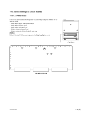
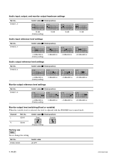
Audio output reference level . Audio input reference level . Monitor output level, fixed/variable selection n Refer to Section 1-16 for removing and reattaching the plug-in boards. < Top View > A B C D E F G H J APR-80 K L M N P 1 S1901 S1900 A S1902 2 S2001 S2000 3 4 5 6 APR-80 Board (Side A) HDW-1800/D1800 1-15 (E) Switch Settings on the APR-80 board. . 1-10. Monitor output reference level . Audio input, output, and monitor output . APR-80 Board If necessary, perform the following audio-related settings using the switches on Circuit Boards 1-10-1.
Audio output reference level . Audio input reference level . Monitor output level, fixed/variable selection n Refer to Section 1-16 for removing and reattaching the plug-in boards. < Top View > A B C D E F G H J APR-80 K L M N P 1 S1901 S1900 A S1902 2 S2001 S2000 3 4 5 6 APR-80 Board (Side A) HDW-1800/D1800 1-15 (E) Switch Settings on the APR-80 board. . 1-10. Monitor output reference level . Audio input, output, and monitor output . APR-80 Board If necessary, perform the following audio-related settings using the switches on Circuit Boards 1-10-1.
Installation Manual
Page 22
... or variable) When the variable level is selected, the level is adjusted with the PHONES level control knob. S1900, S1901 Switch state All OFF 1-16 (E) HDW-1800/D1800 S1902-5, 6 Switch state (\ : Knob position) _3 dBm/600 Z _20 dBm/600 Z +4 dBm/600 Z (Factory setting) 0 dBm/600 Z Monitor output reference level settings Ref. ...) 20 dB (Factory setting) 18 dB Audio input reference level settings Ref. No. S2001 R S2000 Switch state (\ : Knob position) Fixed 1 O 2 N (Factory setting) Variable 1 O 2 N Factory use n Never change the setting. No.
... or variable) When the variable level is selected, the level is adjusted with the PHONES level control knob. S1900, S1901 Switch state All OFF 1-16 (E) HDW-1800/D1800 S1902-5, 6 Switch state (\ : Knob position) _3 dBm/600 Z _20 dBm/600 Z +4 dBm/600 Z (Factory setting) 0 dBm/600 Z Monitor output reference level settings Ref. ...) 20 dB (Factory setting) 18 dB Audio input reference level settings Ref. No. S2001 R S2000 Switch state (\ : Knob position) Fixed 1 O 2 N (Factory setting) Variable 1 O 2 N Factory use n Never change the setting. No.
Installation Manual
Page 23
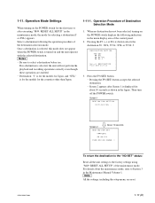
...:SYL 59.94:J Select DESTINATION. To return the destination to the "NO-SET" status: Reset all the unit settings to the factory settings using "M49: RESET ALL SETUP" of the destination selection mode. Select a destination following indication in the maintenance mode, the mode for the first ... panel. 2. When no destination is displayed for the countries other than Japan. 1-11-1. Push SET button. 3. Then turn off the POWER switch. HDW-1800/D1800 Screen 2 About 10 seconds DESTINATION SET COMPLETE 59.94:SYL TURN OFF/ON POWER !! 1-11. Pressing the F9 (SET) button accepts the ...
...:SYL 59.94:J Select DESTINATION. To return the destination to the "NO-SET" status: Reset all the unit settings to the factory settings using "M49: RESET ALL SETUP" of the destination selection mode. Select a destination following indication in the maintenance mode, the mode for the first ... panel. 2. When no destination is displayed for the countries other than Japan. 1-11-1. Push SET button. 3. Then turn off the POWER switch. HDW-1800/D1800 Screen 2 About 10 seconds DESTINATION SET COMPLETE 59.94:SYL TURN OFF/ON POWER !! 1-11. Pressing the F9 (SET) button accepts the ...

Installation Manual
Page 24
... VTR is turned off the power of removal. Yet when reattaching, use care about following points. . Remove the two screws shown in the figure below. 3. Removal 1. Disconnect the cable from the connector on state will damage the control panel. 4. Connector 1-18 (E) HDW-1800/D1800 1-12. After pressing the unlock button, open , press the...
... VTR is turned off the power of removal. Yet when reattaching, use care about following points. . Remove the two screws shown in the figure below. 3. Removal 1. Disconnect the cable from the connector on state will damage the control panel. 4. Connector 1-18 (E) HDW-1800/D1800 1-12. After pressing the unlock button, open , press the...
Installation Manual
Page 26
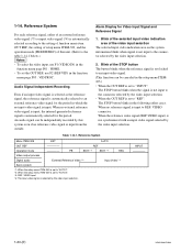
... video signal (REF.VIDEO input) is set the OUT REF, use F1 (VIDEO IN) in the setup menu ITEM105.) . An audio signal can be independently recorded by the video input selection. . INPUT ----- 1-20 (E) HDW-1800/D1800 VIDEO connector. VIDEO input *4: The input video signal is ...input from the outside. To select the video input, use F2 (REF VID) in the following either of the STOP button The button blinks...
... video signal (REF.VIDEO input) is set the OUT REF, use F1 (VIDEO IN) in the setup menu ITEM105.) . An audio signal can be independently recorded by the video input selection. . INPUT ----- 1-20 (E) HDW-1800/D1800 VIDEO connector. VIDEO input *4: The input video signal is ...input from the outside. To select the video input, use F2 (REF VID) in the following either of the STOP button The button blinks...
Installation Manual
Page 27
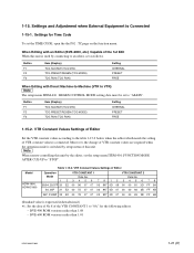
...be set the setup menu ITEM-401: FUNCTION MODE AFTER CUE-UP to "STOP". Moreover, the change of the 1st Edit When this unit. Model HDW-1800, HDW-D1800 Table 1-15-2. VTR Constant Values Settings of Editor Set the VTR constant values according to "AS&IN". Button F1 F2 F3 Item (Display)... the setting of VTR constant values is used by setup menu of the VTR CONSTANT 1 to an editor, set the TIME CODE, open the the P02 : TC page on the function menu. Settings for the following editors. . BVE-900 ROM versions earlier than 1.01 HDW-1800/D1800 1-21 (E) 1-15. Button F1 ...
...be set the setup menu ITEM-401: FUNCTION MODE AFTER CUE-UP to "STOP". Moreover, the change of the 1st Edit When this unit. Model HDW-1800, HDW-D1800 Table 1-15-2. VTR Constant Values Settings of Editor Set the VTR constant values according to "AS&IN". Button F1 F2 F3 Item (Display)... the setting of VTR constant values is used by setup menu of the VTR CONSTANT 1 to an editor, set the TIME CODE, open the the P02 : TC page on the function menu. Settings for the following editors. . BVE-900 ROM versions earlier than 1.01 HDW-1800/D1800 1-21 (E) 1-15. Button F1 ...
Installation Manual
Page 28
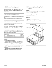
... in PB mode. System Phase Alignment An external reference video signal must be adjusted in board is adjusted during tape playback. . Refer to this unit, use the MULTI CONTROL knob at the P03 : VID PROC page on the function menu. When Connecting to an Analog Switcher Perform the system phase adjustment... the current setting value, and then turn the MULTI CONTROL knob. nance manual, volume-1. Screw with stopper Upper lid (rear) assembly Screw with stopper 1-22 (E) HDW-1800/D1800
... in PB mode. System Phase Alignment An external reference video signal must be adjusted in board is adjusted during tape playback. . Refer to this unit, use the MULTI CONTROL knob at the P03 : VID PROC page on the function menu. When Connecting to an Analog Switcher Perform the system phase adjustment... the current setting value, and then turn the MULTI CONTROL knob. nance manual, volume-1. Screw with stopper Upper lid (rear) assembly Screw with stopper 1-22 (E) HDW-1800/D1800
Installation Manual
Page 31
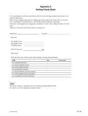
... Write down the setup conditions (switch and so on) under the application. HDW-1800/D1800 A-1 (E) If the unit is changed temporarily by changing the combination of each system, making the sheets are convenient. (Make use of the check sheets in prevention of setting error.) Model name: Serial No... . RS-232C baud rate: bps . For details, refer to the maintenance manual volume 1. If the setting is used frequently by changing operating condition, the setting can be reset easily. ITEM H01: OPERATION HOURS H02: DRUM RUNNING HOURS H03: TAPE RUNNING HOURS...
... Write down the setup conditions (switch and so on) under the application. HDW-1800/D1800 A-1 (E) If the unit is changed temporarily by changing the combination of each system, making the sheets are convenient. (Make use of the check sheets in prevention of setting error.) Model name: Serial No... . RS-232C baud rate: bps . For details, refer to the maintenance manual volume 1. If the setting is used frequently by changing operating condition, the setting can be reset easily. ITEM H01: OPERATION HOURS H02: DRUM RUNNING HOURS H03: TAPE RUNNING HOURS...
Installation Manual
Page 32
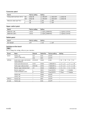
... panel Switch KEY INHIBIT Factory setting OFF Setting [||] ON [||] OFF Switches on the board n Never change the setting of Factory use Channel CH1 CH2 CH1/2/L/R CH1/2 CH1/CH2 L/R L R _ _ _ _ Switch No. S100 S200 S1902 Factory setting All... [||] +4 [||] 0 [||] +4 [||] 0 [||] Fixed [||] Fixed _ _ _ _ [||] _3 [||] _20 [||] _3 [||] _20 [||] _3 [||] _20 [||] Variable [||] Variable A-2 (E) HDW-1800/D1800 Board AE-31 APR-80 HPR-21 SY-340 Name Factory use (HEAD TUNE switch) Audio input, output, and monitor output headroom Audio input reference level Audio output reference level Monitor...
... panel Switch KEY INHIBIT Factory setting OFF Setting [||] ON [||] OFF Switches on the board n Never change the setting of Factory use Channel CH1 CH2 CH1/2/L/R CH1/2 CH1/CH2 L/R L R _ _ _ _ Switch No. S100 S200 S1902 Factory setting All... [||] +4 [||] 0 [||] +4 [||] 0 [||] Fixed [||] Fixed _ _ _ _ [||] _3 [||] _20 [||] _3 [||] _20 [||] _3 [||] _20 [||] Variable [||] Variable A-2 (E) HDW-1800/D1800 Board AE-31 APR-80 HPR-21 SY-340 Name Factory use (HEAD TUNE switch) Audio input, output, and monitor output headroom Audio input reference level Audio output reference level Monitor...
Installation Manual
Page 33
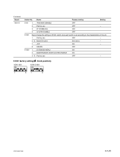
(Continued) Board SS-101 Switch No. : Name Factory setting Setting S101 S1501 S1502 1 : TRACKING ENABLE OFF 2 : Factory use OFF _ 3 : DT WOBBLING OFF 4 : SV ERR DISABLE OFF Never change the settings of S1501 switch since each switch is set according to the characteristics of the unit. 1 : Factory use OFF _ 2 - 6 : Model ID switch See below. _ 7 : J/SY ON _ 8 : 525/625 OFF 1 : EXTENDED MENU ON 2 : MAINTENANCE MODE ACCESS ENABLE ON 3 - 8 : Factory use OFF _ S1501 factory setting ( \ : Knob position) HDW-1800 ON HDW-D1800 ON 1 8 1 8 HDW-1800/D1800 A-3 (E)
(Continued) Board SS-101 Switch No. : Name Factory setting Setting S101 S1501 S1502 1 : TRACKING ENABLE OFF 2 : Factory use OFF _ 3 : DT WOBBLING OFF 4 : SV ERR DISABLE OFF Never change the settings of S1501 switch since each switch is set according to the characteristics of the unit. 1 : Factory use OFF _ 2 - 6 : Model ID switch See below. _ 7 : J/SY ON _ 8 : 525/625 OFF 1 : EXTENDED MENU ON 2 : MAINTENANCE MODE ACCESS ENABLE ON 3 - 8 : Factory use OFF _ S1501 factory setting ( \ : Knob position) HDW-1800 ON HDW-D1800 ON 1 8 1 8 HDW-1800/D1800 A-3 (E)


