
Installation Manual
Page 4
... power from an outlet on the rack, please make sure that the rack does not achieve hazardous condition due to the specifications of the Operation Manual. 6. Right, Left: 4 cm (1.6 inches) or more Rear: 40 cm (16 inches) or more Für Kunden in Deutschland Entsorgungshinweis: Bitte werfen Sie nur entladene Batterien in...
... power from an outlet on the rack, please make sure that the rack does not achieve hazardous condition due to the specifications of the Operation Manual. 6. Right, Left: 4 cm (1.6 inches) or more Rear: 40 cm (16 inches) or more Für Kunden in Deutschland Entsorgungshinweis: Bitte werfen Sie nur entladene Batterien in...
Installation Manual
Page 5
... Panel Unit 1-18 (E) 1-13. Power Cord 1-2 (E) 1-5. Switching Search Dial Mode 1-19 (E) 1-14. Installation 1-1. Installation Space 1-3 (E) 1-6. VTR Constant Values Settings of this manual 2 (E) Related manuals 2 (E) 1. Voltage and Power Requirements 1-2 (E) 1-4-2. Table of Contents Manual Structure Purpose of Editor ..... 1-21 (E) 1-15-3. Installation Procedure 1-1 (E) 1-2. Power Supply 1-2 (E) 1-4-1. Matching Connectors and Cables 1-9 (E) 1-8. Switch Settings on Circuit Boards 1-15 (E) 1-10...
... Panel Unit 1-18 (E) 1-13. Power Cord 1-2 (E) 1-5. Switching Search Dial Mode 1-19 (E) 1-14. Installation 1-1. Installation Space 1-3 (E) 1-6. VTR Constant Values Settings of this manual 2 (E) Related manuals 2 (E) 1. Voltage and Power Requirements 1-2 (E) 1-4-2. Table of Contents Manual Structure Purpose of Editor ..... 1-21 (E) 1-15-3. Installation Procedure 1-1 (E) 1-2. Power Supply 1-2 (E) 1-4-1. Matching Connectors and Cables 1-9 (E) 1-8. Switch Settings on Circuit Boards 1-15 (E) 1-10...
Installation Manual
Page 6
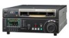
... on request) Volume-1 : Service Instruction Volume-2 : Parts List, Block Diagrams, and Board Layouts Volume-3 : Schematic Diagrams These manuals describe the maintenace and service information (service overview, adjustments, board layouts, schematic diagrams, detailed parts list, etc.) for semiconductors used... together with this unit.) This manual is the installation manual of the HD Digital Videocassette Recorder HDW-1800/D1800. Manual Structure Purpose of this manual This manual is necessary for this unit. . This manual is intended for use by trained system ...
... on request) Volume-1 : Service Instruction Volume-2 : Parts List, Block Diagrams, and Board Layouts Volume-3 : Schematic Diagrams These manuals describe the maintenace and service information (service overview, adjustments, board layouts, schematic diagrams, detailed parts list, etc.) for semiconductors used... together with this unit.) This manual is the installation manual of the HD Digital Videocassette Recorder HDW-1800/D1800. Manual Structure Purpose of this manual This manual is necessary for this unit. . This manual is intended for use by trained system ...
Installation Manual
Page 7
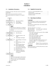
... 1-1. Start Determination of the cabinet and the front and rear panels. Do not reuse the packing materials. Reference System 1-15. Operation manual CD-ROM (PDF 1 . Rack Mounting *Connection 1-7. Matching Connectors and Cables 1-8. Settings and Adjustment when External Equipment is impossible to ... about detail of any other strong lights. . Areas near heat sources. . Areas with sufficient air circulation. The operation manual is required to prevent internal heat build-up. Operating Conditions 1-4. Power Supply 1-5. Signal Inputs and Outputs *Initial setup *...
... 1-1. Start Determination of the cabinet and the front and rear panels. Do not reuse the packing materials. Reference System 1-15. Operation manual CD-ROM (PDF 1 . Rack Mounting *Connection 1-7. Matching Connectors and Cables 1-8. Settings and Adjustment when External Equipment is impossible to ... about detail of any other strong lights. . Areas near heat sources. . Areas with sufficient air circulation. The operation manual is required to prevent internal heat build-up. Operating Conditions 1-4. Power Supply 1-5. Signal Inputs and Outputs *Initial setup *...
Installation Manual
Page 16
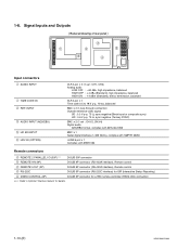
... (RS-232C interface) for ISR (Interactive Status Reporting) 4 VIDEO CONTROL (9P) D-SUB 9P connector for a TBC remote controller (HKDV-900) connection *** : Refer to Optional "Interface manual" for details. 1-10 (E) HDW-1800/D1800 Signal Inputs and Outputs Reduced drawing of rear panel 3 1 2 5 6 4 Input connectors 1 AUDIO INPUT 1 TIME CODE IN 2 REF...
... (RS-232C interface) for ISR (Interactive Status Reporting) 4 VIDEO CONTROL (9P) D-SUB 9P connector for a TBC remote controller (HKDV-900) connection *** : Refer to Optional "Interface manual" for details. 1-10 (E) HDW-1800/D1800 Signal Inputs and Outputs Reduced drawing of rear panel 3 1 2 5 6 4 Input connectors 1 AUDIO INPUT 1 TIME CODE IN 2 REF...
Installation Manual
Page 19
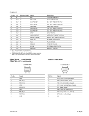
... kZ pull up to +5 V (close/open) Output ; 10 kZ pull up to +5 V (0 V or open) *2: The pins described as O mark are possible to the optional interface manual for changing the setting. Data Carrier Detect (Input) RXD ; REMOTE1-IN: 9-pin (female) REMOTE1-OUT: 9-pin (female) External view 5 1 Pin No. 1 2 3 4 5 6 7 8 9 96 Signal GND RM...
... kZ pull up to +5 V (close/open) Output ; 10 kZ pull up to +5 V (0 V or open) *2: The pins described as O mark are possible to the optional interface manual for changing the setting. Data Carrier Detect (Input) RXD ; REMOTE1-IN: 9-pin (female) REMOTE1-OUT: 9-pin (female) External view 5 1 Pin No. 1 2 3 4 5 6 7 8 9 96 Signal GND RM...
Installation Manual
Page 20
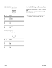
Switch Settings on Connector Panel When the unit is installed, be sure to the operation manual "Section 2 Location and Function of reference video input 1-14 (E) HDW-1800/D1800 VIDEO CONTROL: 9-pin (female) External view 5 1 Pin No. 1 2 3 4 5 6 7 8 9 96 Signal GND RM TX (_) RM RX (+) GND -- Refer to perform the following setup. Analog audio input level/600 Z termination switches . 75 Z termination switch of Parts" for setup. . GND RM TX (+) RM RX (_) GND HDV IN (OPTION): 6-pin External view 1 2 3 4 5 6 Pin No. 1 2 3 4 5 6 Signal VP VG NTPB TPB NTPA TPA 1-9.
Switch Settings on Connector Panel When the unit is installed, be sure to the operation manual "Section 2 Location and Function of reference video input 1-14 (E) HDW-1800/D1800 VIDEO CONTROL: 9-pin (female) External view 5 1 Pin No. 1 2 3 4 5 6 7 8 9 96 Signal GND RM TX (_) RM RX (+) GND -- Refer to perform the following setup. Analog audio input level/600 Z termination switches . 75 Z termination switch of Parts" for setup. . GND RM TX (+) RM RX (_) GND HDV IN (OPTION): 6-pin External view 1 2 3 4 5 6 Pin No. 1 2 3 4 5 6 Signal VP VG NTPB TPB NTPA TPA 1-9.
Installation Manual
Page 23
... maintenance mode. When no destination is for the models for selecting a destination (J or SYL) appears. For details about 10 seconds as shown in the Maintenance Manual Volume-1. n All the settings, including the setup menu, are enabled. . Be sure to Section 3 in the figure. Screen 1 DESTINATION SETTING INITIALIZING... To return the destination...
... maintenance mode. When no destination is for the models for selecting a destination (J or SYL) appears. For details about 10 seconds as shown in the Maintenance Manual Volume-1. n All the settings, including the setup menu, are enabled. . Be sure to Section 3 in the figure. Screen 1 DESTINATION SETTING INITIALIZING... To return the destination...
Installation Manual
Page 28
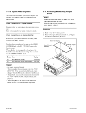
... to the PB mode. . Button Item Display F3 SYSTEM SYNC PHASE SYNC PHS F4 SYSTEM SYNC PHASE (fine djustmen) SYNC FIN m . Be sure to the manual of the digital switcher for details. The system phase does not change even if the SYNC PHS/SYNC FIN is adjusted in PB mode. The... playback sound may be adjusted in board is adjusted so that SC-H conforms to the manual of the extended setup menu. 1-16. When the plug-in ITEM-719 and -720 of the analog switcher. Removing 1. System Phase Alignment An external reference...
... to the PB mode. . Button Item Display F3 SYSTEM SYNC PHASE SYNC PHS F4 SYSTEM SYNC PHASE (fine djustmen) SYNC FIN m . Be sure to the manual of the digital switcher for details. The system phase does not change even if the SYNC PHS/SYNC FIN is adjusted in PB mode. The... playback sound may be adjusted in board is adjusted so that SC-H conforms to the manual of the extended setup menu. 1-16. When the plug-in ITEM-719 and -720 of the analog switcher. Removing 1. System Phase Alignment An external reference...

Installation Manual
Page 30
... EJECT label to be tighten. (Unthreading end state) 11. n On completely winding up the tape into the cassette, the M gear will be able to wind manually the tape. 7. Check that the unit is slacken. 12. m . Pull the ME wire for the tape not to catch in the state to take up...
... EJECT label to be tighten. (Unthreading end state) 11. n On completely winding up the tape into the cassette, the M gear will be able to wind manually the tape. 7. Check that the unit is slacken. 12. m . Pull the ME wire for the tape not to catch in the state to take up...
Installation Manual
Page 31
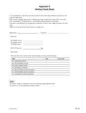
... in prevention of setup menu can be saved and read using a Memory Stick. If the setting is recommended to attach the sheets to the maintenance manual volume 1. HDW-1800/D1800 A-1 (E) ITEM H01: OPERATION HOURS H02: DRUM RUNNING HOURS H03: TAPE RUNNING HOURS H04: THREADING COUNTER H12: DRUM RUNNING HOURS (Resettable) H13...
... in prevention of setup menu can be saved and read using a Memory Stick. If the setting is recommended to attach the sheets to the maintenance manual volume 1. HDW-1800/D1800 A-1 (E) ITEM H01: OPERATION HOURS H02: DRUM RUNNING HOURS H03: TAPE RUNNING HOURS H04: THREADING COUNTER H12: DRUM RUNNING HOURS (Resettable) H13...


