
Product Brochure (v2222)
Page 7
..., AES/EBU, 48 kHz fixed, complies with AES-3id-1995 D-sub 9-pin (x2), Sony 9-pin remote interface D-sub 9-pin (x1), RS-232C interface D-sub 50-pin (x1)...selectable) T1=50 µs, T2=15 µs PSW 4x16 Rack mount screw (x4), Operation manual (x1), Installation manual (x1) *ISR: Interactive Status Reporting 7 SPECIFICATIONS General Power requirements Power consumption Operating temperature Storage... Analog input to analog output Head room Emphasis (ON/OFF selectable in REC mode) Supplied accessories DVW-M2000/M2000P DVW-2000/2000P AC 100 V to 240 V, 50/60 Hz 220 W +5 ˚C to...
..., AES/EBU, 48 kHz fixed, complies with AES-3id-1995 D-sub 9-pin (x2), Sony 9-pin remote interface D-sub 9-pin (x1), RS-232C interface D-sub 50-pin (x1)...selectable) T1=50 µs, T2=15 µs PSW 4x16 Rack mount screw (x4), Operation manual (x1), Installation manual (x1) *ISR: Interactive Status Reporting 7 SPECIFICATIONS General Power requirements Power consumption Operating temperature Storage... Analog input to analog output Head room Emphasis (ON/OFF selectable in REC mode) Supplied accessories DVW-M2000/M2000P DVW-2000/2000P AC 100 V to 240 V, 50/60 Hz 220 W +5 ˚C to...
Product Manual (Operation Manual 1st Edition (Revised 6))
Page 10
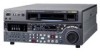
...Serial Digital Interface) SMPTE 259M input (component digital video/audio (4 channels)) • SDI SMPTE 259M output (component digital video/ audio (DVW-M2000/M2000P: 8 channels; It can be set from the control panel by this unit has a front panel which provides a wide range of ... audio signals, similarly, are based on a conventional VTR. ...1) The DVW-2000/2000P is digital, providing high stability and reliability. Newly developed multifunction control panel While a compact 4U size, this manual. 1) High-precision digital signal processing and range of interfaces While supporting ...
...Serial Digital Interface) SMPTE 259M input (component digital video/audio (4 channels)) • SDI SMPTE 259M output (component digital video/ audio (DVW-M2000/M2000P: 8 channels; It can be set from the control panel by this unit has a front panel which provides a wide range of ... audio signals, similarly, are based on a conventional VTR. ...1) The DVW-2000/2000P is digital, providing high stability and reliability. Newly developed multifunction control panel While a compact 4U size, this manual. 1) High-precision digital signal processing and range of interfaces While supporting ...
Product Manual (Operation Manual 1st Edition (Revised 6))
Page 111
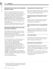
... value for the video signal output level. Sets the chroma signal output level (-∞ to +3 dB). PRESET: Regardless of the HOME page. Manual setting: With the displayed setting flashing, you can rotate the MULTI CONTROL knob to the standard value. Chapter 11 Function Menu Page 2 Item F1...(VIDEO) F3 (CHROMA) F4 (HUE) (525line mode)/ (C PHAS) (625line mode) F5 (SETUP) (525-line mode)/ (BLACK) (625line mode) F6 (YC DLY) (DVW-M2000/ M2000P only) Setting Selects the control method for the chroma signal output level. REMOTE: Use the optional BVR-50/50P Remote Control Unit to adjust the...
... value for the video signal output level. Sets the chroma signal output level (-∞ to +3 dB). PRESET: Regardless of the HOME page. Manual setting: With the displayed setting flashing, you can rotate the MULTI CONTROL knob to the standard value. Chapter 11 Function Menu Page 2 Item F1...(VIDEO) F3 (CHROMA) F4 (HUE) (525line mode)/ (C PHAS) (625line mode) F5 (SETUP) (525-line mode)/ (BLACK) (625line mode) F6 (YC DLY) (DVW-M2000/ M2000P only) Setting Selects the control method for the chroma signal output level. REMOTE: Use the optional BVR-50/50P Remote Control Unit to adjust the...
Product Manual (Operation Manual 1st Edition (Revised 6))
Page 125
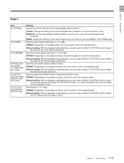
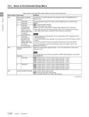
... to "ENA" on the connector panel. IN: Only the IN connector is effective whether in local or remote mode. PANEL: Allows you to the Maintenance Manual Volume 1. 12-11 Chapter 12 Setup Menus On how to define user-defined function keys in the HOME2 page, refer to select i&o, in, or out... local or remote mode. OFF : Do not open the Tele-File menu automatically when a cassette with the control panel of the VTRs. 202 CF FLAG (DVW-M2000P/ Select the mode for data modification operations in the Tele-File CONTINUE menu screen. Menu items in the range 200 to 299, relating to the...
... to "ENA" on the connector panel. IN: Only the IN connector is effective whether in local or remote mode. PANEL: Allows you to the Maintenance Manual Volume 1. 12-11 Chapter 12 Setup Menus On how to define user-defined function keys in the HOME2 page, refer to select i&o, in, or out... local or remote mode. OFF : Do not open the Tele-File menu automatically when a cassette with the control panel of the VTRs. 202 CF FLAG (DVW-M2000P/ Select the mode for data modification operations in the Tele-File CONTINUE menu screen. Menu items in the range 200 to 299, relating to the...
Product Manual (Operation Manual 1st Edition (Revised 6))
Page 142
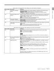
... the setting of maintenance menu item M372. 8-channel For more information about the maintenance menu item M372, refer to the recording tape Maintenance Manual. 824 ANALOG LINE OUTPUT Select the analog audio signals (tracks 1 to 8) to be assigned to audio output SELECT channels 1 to audio...) Item number Item name Settings 823 NON-AUDIO FLAG PB Controls the non-audio flag when the playback format is non-audio) (DVW-M2000/ AUTO: As follows, depending on the DVWM2000/M2000P. 1 CH1/CH2 tr1/2 : Assign tracks 1 and 2 to audio output channels 1 and 2 tr3/4: Assign tracks 3 and 4 to ...
... the setting of maintenance menu item M372. 8-channel For more information about the maintenance menu item M372, refer to the recording tape Maintenance Manual. 824 ANALOG LINE OUTPUT Select the analog audio signals (tracks 1 to 8) to be assigned to audio output SELECT channels 1 to audio...) Item number Item name Settings 823 NON-AUDIO FLAG PB Controls the non-audio flag when the playback format is non-audio) (DVW-M2000/ AUTO: As follows, depending on the DVWM2000/M2000P. 1 CH1/CH2 tr1/2 : Assign tracks 1 and 2 to audio output channels 1 and 2 tr3/4: Assign tracks 3 and 4 to ...
Product Manual (dvwm2000 installation manual)
Page 3
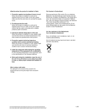
... is installed in a rack and is installed in Rack: 1. HDW-2000/M2000/M2000P/S2000/S2000P/M2100/M2100P, DVW-2000/2000P/M2000/M2000P MSW-2000/A2000/A2000P/M2000/M2000P/M2000E/M2000EP/M2100/M2100P/M2100E/M2100EP 1 (P) Install the equipment while taking the operating... temperature of the equipment into consideration For the operating temperature of the equipment, refer to obtain proper exhaust and radiation of the Operation Manual...
... is installed in a rack and is installed in Rack: 1. HDW-2000/M2000/M2000P/S2000/S2000P/M2100/M2100P, DVW-2000/2000P/M2000/M2000P MSW-2000/A2000/A2000P/M2000/M2000P/M2000E/M2000EP/M2100/M2100P/M2100E/M2100EP 1 (P) Install the equipment while taking the operating... temperature of the equipment into consideration For the operating temperature of the equipment, refer to obtain proper exhaust and radiation of the Operation Manual...
Product Manual (dvwm2000 installation manual)
Page 5
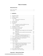
.... VTR Constant Values Settings of this manual 2 Related manuals ...2 1. System Phase Alignment 1-28 1-15-4. Voltage and Power Requirements 1-2 1-4-2. Operation Mode Settings (For DVW-2000/M2000 Only 1-21 1-11-1. Removing.../Reattaching Plug-in Tape Slacking 1-30 Appendix A Setting Check Sheet HDW-2000/M2000/M2000P/S2000/S2000P/M2100/M2100P, DVW-2000/2000P/M2000/M2000P 1 MSW-2000/A2000/A2000P/M2000/M2000P...
.... VTR Constant Values Settings of this manual 2 Related manuals ...2 1. System Phase Alignment 1-28 1-15-4. Voltage and Power Requirements 1-2 1-4-2. Operation Mode Settings (For DVW-2000/M2000 Only 1-21 1-11-1. Removing.../Reattaching Plug-in Tape Slacking 1-30 Appendix A Setting Check Sheet HDW-2000/M2000/M2000P/S2000/S2000P/M2100/M2100P, DVW-2000/2000P/M2000/M2000P 1 MSW-2000/A2000/A2000P/M2000/M2000P...
Product Manual (dvwm2000 installation manual)
Page 6
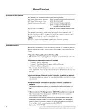
... HDW-2000/M2000/M2000P/S2000/S2000P HD Digital Videocassette Player HDW-M2100/M2100P Digital Videocassette Recorder DVW-2000/2000P/M2000/M2000P, MSW-2000/A2000/A2000P/M2000/ M2000P/M2000E/M2000EP Digital Videocassette Player MSW-M2100/M2100P/M2100E/M2100EP This manual is intended for ...n The figures in this unit. Semiconductors that is the installation manual of the following manuals are available for this CD-ROM are required, please contact your local Sony Sales Office/Service Center. . Maintenance Manual (Available on request) This "Semiconductor Pin Assignments" CD-ROM allows...
... HDW-2000/M2000/M2000P/S2000/S2000P HD Digital Videocassette Player HDW-M2100/M2100P Digital Videocassette Recorder DVW-2000/2000P/M2000/M2000P, MSW-2000/A2000/A2000P/M2000/ M2000P/M2000E/M2000EP Digital Videocassette Player MSW-M2100/M2100P/M2100E/M2100EP This manual is intended for ...n The figures in this unit. Semiconductors that is the installation manual of the following manuals are available for this CD-ROM are required, please contact your local Sony Sales Office/Service Center. . Maintenance Manual (Available on request) This "Semiconductor Pin Assignments" CD-ROM allows...
Product Manual (dvwm2000 installation manual)
Page 7
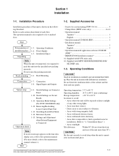
...on the following flowchart. HDW-2000/M2000/M2000P/S2000/S2000P/M2100/M2100P, DVW-2000/2000P/M2000/M2000P MSW-2000/A2000/A2000P/M2000/M2000P/M2000E/M2000EP/M2100/M2100P/M2100E/M2100EP 1-1 Operating... Conditions 1-4. Signal Inputs and Outputs . Operation Mode Settings (For DVW-2000/M2000 only) 1-12. Areas that is operat- Installation Procedure 1-2. Supplied Accessories Installation procedure of the unit more details, refer to the maintenance manual...
...on the following flowchart. HDW-2000/M2000/M2000P/S2000/S2000P/M2100/M2100P, DVW-2000/2000P/M2000/M2000P MSW-2000/A2000/A2000P/M2000/M2000P/M2000E/M2000EP/M2100/M2100P/M2100E/M2100EP 1-1 Operating... Conditions 1-4. Signal Inputs and Outputs . Operation Mode Settings (For DVW-2000/M2000 only) 1-12. Areas that is operat- Installation Procedure 1-2. Supplied Accessories Installation procedure of the unit more details, refer to the maintenance manual...
Product Manual (dvwm2000 installation manual)
Page 17
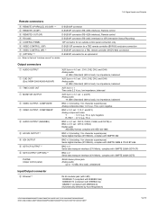
...connector for a TBC remote controller (HKDV-900) connection 4 (OPTION) *4, 5 D-SUB 9P connector for an optional kit *** : Refer to Optional "Interface manual" for character superimpose) Serial digital interface (270 Mbit/s), complies with SMPTE 259M & ITU-R BT.656 BNC x 2 Serial data transport interface (270 Mbit/s), ... with IEEE802.3u) 10BASE-T (compliant with IEEE802.3i) (Automatically detected by Auto-Negotiation) HDW-2000/M2000/M2000P/S2000/S2000P/M2100/M2100P, DVW-2000/2000P/M2000/M2000P MSW-2000/A2000/A2000P/M2000/M2000P/M2000E/M2000EP/M2100/M2100P/M2100E/M2100EP 1-11 1-8.
...connector for a TBC remote controller (HKDV-900) connection 4 (OPTION) *4, 5 D-SUB 9P connector for an optional kit *** : Refer to Optional "Interface manual" for character superimpose) Serial digital interface (270 Mbit/s), complies with SMPTE 259M & ITU-R BT.656 BNC x 2 Serial data transport interface (270 Mbit/s), ... with IEEE802.3u) 10BASE-T (compliant with IEEE802.3i) (Automatically detected by Auto-Negotiation) HDW-2000/M2000/M2000P/S2000/S2000P/M2100/M2100P, DVW-2000/2000P/M2000/M2000P MSW-2000/A2000/A2000P/M2000/M2000P/M2000E/M2000EP/M2100/M2100P/M2100E/M2100EP 1-11 1-8.
Product Manual (dvwm2000 installation manual)
Page 20
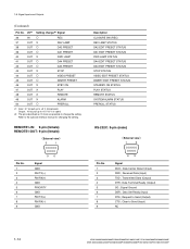
... Data Carrier Detect (Input) RXD ; Signal Ground DSR ; Transmitted Data (Output) DTR ; Data Set Ready (Input) RTS ; Request to the optional interface manual for changing the setting. Refer to Send (Output) CTS ; Received Data (Input) TXD ; Clear to change the setting. Data Terminal Ready (Output) SG ...) Output ; 10 kZ pull up to +5 V (0 V or open) *2: The pins described as O mark are possible to Send (Input) NC 1-14 HDW-2000/M2000/M2000P/S2000/S2000P/M2100/M2100P, DVW-2000/2000P/M2000/M2000P MSW-2000/A2000/A2000P/M2000/M2000P/M2000E/M2000EP/M2100/M2100P/M2100E/M2100EP
... Data Carrier Detect (Input) RXD ; Signal Ground DSR ; Transmitted Data (Output) DTR ; Data Set Ready (Input) RTS ; Request to the optional interface manual for changing the setting. Refer to Send (Output) CTS ; Received Data (Input) TXD ; Clear to change the setting. Data Terminal Ready (Output) SG ...) Output ; 10 kZ pull up to +5 V (0 V or open) *2: The pins described as O mark are possible to Send (Input) NC 1-14 HDW-2000/M2000/M2000P/S2000/S2000P/M2100/M2100P, DVW-2000/2000P/M2000/M2000P MSW-2000/A2000/A2000P/M2000/M2000P/M2000E/M2000EP/M2100/M2100P/M2100E/M2100EP
Product Manual (dvwm2000 installation manual)
Page 21
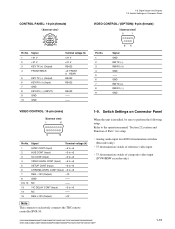
Refer to the operation manual "Section 2 Location and Function of composite video input (DVW/MSW recorder only) HDW-2000/M2000/M2000P/S2000/S2000P/M2100/M2100P, DVW-2000/2000P/M2000/M2000P MSW-2000/A2000/A2000P/M2000/M2000P/M2000E/M2000EP/M2100/M2100P/M2100E/M2100EP 1-15 VIDEO CONTROL / (OPTION): 9-pin (female) External view 5 1 Pin No. 1 2 3 4 5 6 7 8 9 96 Signal GND RM TX...
Refer to the operation manual "Section 2 Location and Function of composite video input (DVW/MSW recorder only) HDW-2000/M2000/M2000P/S2000/S2000P/M2100/M2100P, DVW-2000/2000P/M2000/M2000P MSW-2000/A2000/A2000P/M2000/M2000P/M2000E/M2000EP/M2100/M2100P/M2100E/M2100EP 1-15 VIDEO CONTROL / (OPTION): 9-pin (female) External view 5 1 Pin No. 1 2 3 4 5 6 7 8 9 96 Signal GND RM TX...
Product Manual (dvwm2000 installation manual)
Page 26
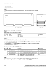
... 2A 3 4 5 6 SS-89 Board (Side A) < Top View > Operation mode settings (for MSW-2000 only) n Refer to Section 1 of the maintenance manual volume 1 for the DVW series settings. No. They are switched, it will disappear by the NTSC model or PAL model. . Bit Name S1501 8 525/625 Description OFF: 525...the above settings are not required for the details of ITEM-F series. 1-20 HDW-2000/M2000/M2000P/S2000/S2000P/M2100/M2100P, DVW-2000/2000P/M2000/M2000P MSW-2000/A2000/A2000P/M2000/M2000P/M2000E/M2000EP/M2100/M2100P/M2100E/M2100EP Switch Settings on . SS-89 Board n If necessary, ...
... 2A 3 4 5 6 SS-89 Board (Side A) < Top View > Operation mode settings (for MSW-2000 only) n Refer to Section 1 of the maintenance manual volume 1 for the DVW series settings. No. They are switched, it will disappear by the NTSC model or PAL model. . Bit Name S1501 8 525/625 Description OFF: 525...the above settings are not required for the details of ITEM-F series. 1-20 HDW-2000/M2000/M2000P/S2000/S2000P/M2100/M2100P, DVW-2000/2000P/M2000/M2000P MSW-2000/A2000/A2000P/M2000/M2000P/M2000E/M2000EP/M2100/M2100P/M2100E/M2100EP Switch Settings on . SS-89 Board n If necessary, ...
Product Manual (dvwm2000 installation manual)
Page 27
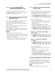
... the destination to the "NO-SET" status: Reset all the unit settings to "1-1-5. HDW-2000/M2000/M2000P/S2000/S2000P/M2100/M2100P, DVW-2000/2000P/M2000/M2000P MSW-2000/A2000/A2000P/M2000/M2000P/M2000E/M2000EP/M2100/M2100P/M2100E/M2100EP 1-21 DESTINATION SEL - J RETURN _ + SET F1 F2 F3 ... as a destination ("J" blinks) DESTINATION SEL - Press the F5 (SET) button. . Be sure to the original indication shown in the Maintenance Manual Volume-1. SYL RETURN _ + SET F1 F2 F3 F4 F5 F6 When "J" is selected, the unit will not perform the playback and recording operations...
... the destination to the "NO-SET" status: Reset all the unit settings to "1-1-5. HDW-2000/M2000/M2000P/S2000/S2000P/M2100/M2100P, DVW-2000/2000P/M2000/M2000P MSW-2000/A2000/A2000P/M2000/M2000P/M2000E/M2000EP/M2100/M2100P/M2100E/M2100EP 1-21 DESTINATION SEL - J RETURN _ + SET F1 F2 F3 ... as a destination ("J" blinks) DESTINATION SEL - Press the F5 (SET) button. . Be sure to the original indication shown in the Maintenance Manual Volume-1. SYL RETURN _ + SET F1 F2 F3 F4 F5 F6 When "J" is selected, the unit will not perform the playback and recording operations...
Product Manual (dvwm2000 installation manual)
Page 28
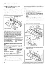
... Lower Control Panel Unit 1-12. Turn off before disconnecting the cable. As to the setting of ITEM-117, refer to the operation manual of the connected cable is detachable from the setup extended menu ITEM-117. Unlock button POWER O I Power OFF Unlock button BVTT3 x...view Cable BVTT3 x 6 Cable holder Connector 5. Lower control panel unit 1-22 HDW-2000/M2000/M2000P/S2000/S2000P/M2100/M2100P, DVW-2000/2000P/M2000/M2000P MSW-2000/A2000/A2000P/M2000/M2000P/M2000E/M2000EP/M2100/M2100P/M2100E/M2100EP Removing/Reattaching Lower Control Panel Unit The lower control panel unit ...
... Lower Control Panel Unit 1-12. Turn off before disconnecting the cable. As to the setting of ITEM-117, refer to the operation manual of the connected cable is detachable from the setup extended menu ITEM-117. Unlock button POWER O I Power OFF Unlock button BVTT3 x...view Cable BVTT3 x 6 Cable holder Connector 5. Lower control panel unit 1-22 HDW-2000/M2000/M2000P/S2000/S2000P/M2100/M2100P, DVW-2000/2000P/M2000/M2000P MSW-2000/A2000/A2000P/M2000/M2000P/M2000E/M2000EP/M2100/M2100P/M2100E/M2100EP Removing/Reattaching Lower Control Panel Unit The lower control panel unit ...
Product Manual (dvwm2000 installation manual)
Page 34
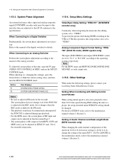
... the maintenance manual volume-1 (Section 3). 1-28 HDW-2000/M2000/M2000P/S2000/S2000P/M2100/M2100P, DVW-2000/2000P/M2000/M2000P MSW-2000/A2000/A2000P/M2000/M2000P/M2000E/M2000EP/M2100/M2100P/M2100E/M2100EP To adjust the system phase of this setup menu is shifted to the maintenance manual volume-1 (Section...momentarily interrupted if the SYNC/SC is Connected 1-15-3. Other Settings When make the following settings, please contact your local Sony Sales Office/Service Center. Settings and Adjustment when External Equipment is adjusted during EE/PB switching in ITEM-719 and -720...
... the maintenance manual volume-1 (Section 3). 1-28 HDW-2000/M2000/M2000P/S2000/S2000P/M2100/M2100P, DVW-2000/2000P/M2000/M2000P MSW-2000/A2000/A2000P/M2000/M2000P/M2000E/M2000EP/M2100/M2100P/M2100E/M2100EP To adjust the system phase of this setup menu is shifted to the maintenance manual volume-1 (Section...momentarily interrupted if the SYNC/SC is Connected 1-15-3. Other Settings When make the following settings, please contact your local Sony Sales Office/Service Center. Settings and Adjustment when External Equipment is adjusted during EE/PB switching in ITEM-719 and -720...
Product Manual (dvwm2000 installation manual)
Page 35
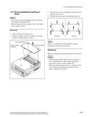
...both ends of the board in the square holes on the motherboard. . HDW-2000/M2000/M2000P/S2000/S2000P/M2100/M2100P, DVW-2000/2000P/M2000/M2000P MSW-2000/A2000/A2000P/M2000/M2000P/M2000E/M2000EP/M2100/M2100P/M2100E/M2100EP 1-29 Reattaching When reattaching the board, install in board is... replaced, refer to their structural feature. When the plug-in the reverse order of the arrows. 4. nance manual, volume-1....
...both ends of the board in the square holes on the motherboard. . HDW-2000/M2000/M2000P/S2000/S2000P/M2100/M2100P, DVW-2000/2000P/M2000/M2000P MSW-2000/A2000/A2000P/M2000/M2000P/M2000E/M2000EP/M2100/M2100P/M2100E/M2100EP 1-29 Reattaching When reattaching the board, install in board is... replaced, refer to their structural feature. When the plug-in the reverse order of the arrows. 4. nance manual, volume-1....
Product Manual (dvwm2000 installation manual)
Page 36
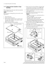
...to take the ME wire off the power. 2. Pull the ME wire for MSW-2000, skip this unit, follow the steps below to wind manually the tape. 7. Rotate the M gear of the threading motor block in direction of arrow shown in the EJECT label by eye that the ...holder 1-30 Removal Installation M gear EJECT label ME wire EJECT label Wire holder Gear box assembly HDW-2000/M2000/M2000P/S2000/S2000P/M2100/M2100P, DVW-2000/2000P/M2000/M2000P MSW-2000/A2000/A2000P/M2000/M2000P/M2000E/M2000EP/M2100/M2100P/M2100E/M2100EP Taking Out the Cassette in the direction of a tape guide. . 1-17.
...to take the ME wire off the power. 2. Pull the ME wire for MSW-2000, skip this unit, follow the steps below to wind manually the tape. 7. Rotate the M gear of the threading motor block in direction of arrow shown in the EJECT label by eye that the ...holder 1-30 Removal Installation M gear EJECT label ME wire EJECT label Wire holder Gear box assembly HDW-2000/M2000/M2000P/S2000/S2000P/M2100/M2100P, DVW-2000/2000P/M2000/M2000P MSW-2000/A2000/A2000P/M2000/M2000P/M2000E/M2000EP/M2100/M2100P/M2100E/M2100EP Taking Out the Cassette in the direction of a tape guide. . 1-17.
Product Manual (dvwm2000 installation manual)
Page 39
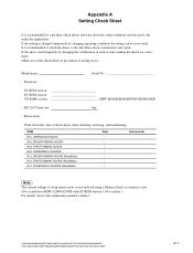
... setting error.) Model name: Serial No . RS-232C baud rate: bps . It is recommended to the maintenance manual volume 1. HDW-2000/M2000/M2000P/S2000/S2000P/M2100/M2100P, DVW-2000/2000P/M2000/M2000P MSW-2000/A2000/A2000P/M2000/M2000P/M2000E/M2000EP/M2100/M2100P/M2100E/M2100EP A-1 If the setting is used frequently by changing operating condition, the...
... setting error.) Model name: Serial No . RS-232C baud rate: bps . It is recommended to the maintenance manual volume 1. HDW-2000/M2000/M2000P/S2000/S2000P/M2100/M2100P, DVW-2000/2000P/M2000/M2000P MSW-2000/A2000/A2000P/M2000/M2000P/M2000E/M2000EP/M2100/M2100P/M2100E/M2100EP A-1 If the setting is used frequently by changing operating condition, the...


