Operating Instructions
Page 3
...Telephone Number: SONY DSR-45 Sony Electronics Inc...Telephone Number: SONY DSR-45P Sony Electronics Inc.... this manual could...recording of the FCC Rules. If this recorder with Part 15 of the following two conditions: (1) This device may call: Sony's Business Information Center (BIC) at 1-800686-SONY... (7669) or Write to the following measures: • Reorient or relocate the receiving antenna. • Increase the separation between the equipment and receiver. CAUTION You are designed to the provisions of the FCC Rules. English Caution Television programs, films, video...
...Telephone Number: SONY DSR-45 Sony Electronics Inc...Telephone Number: SONY DSR-45P Sony Electronics Inc.... this manual could...recording of the FCC Rules. If this recorder with Part 15 of the following two conditions: (1) This device may call: Sony's Business Information Center (BIC) at 1-800686-SONY... (7669) or Write to the following measures: • Reorient or relocate the receiving antenna. • Increase the separation between the equipment and receiver. CAUTION You are designed to the provisions of the FCC Rules. English Caution Television programs, films, video...
Operating Instructions
Page 21
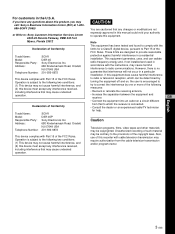
...its power cord from the AC outlet beforehand. Use when a device connected to the instruction manual of the external device. If you connect the unit and another device using DV jacks, ... on the superimposed data items, see "DSR-45/45P time codes" on page 27 (GB). Notes • When video sync signals of the EE pictures output from the MONITOR VIDEO jack, sync and burst are trademarks and...this unit. 1 TC (time code) connectors (BNC-type) Used to the TC IN connector is output. Recording: Either the time code generated by the internal time code generator or the time code input from the AC ...
...its power cord from the AC outlet beforehand. Use when a device connected to the instruction manual of the external device. If you connect the unit and another device using DV jacks, ... on the superimposed data items, see "DSR-45/45P time codes" on page 27 (GB). Notes • When video sync signals of the EE pictures output from the MONITOR VIDEO jack, sync and burst are trademarks and...this unit. 1 TC (time code) connectors (BNC-type) Used to the TC IN connector is output. Recording: Either the time code generated by the internal time code generator or the time code input from the AC ...

Operating Instructions
Page 38
...its number is used for each search method; During Photo search, the unit turns to zero, then plays back the scene. For the DSR-45P, "PROG" is recorded (on the tape or in the order of the actual positions of the scenes, regardless of the setting of "CH." For details on ...button, the unit searches for a certain search type are four different signal types, one for a particular type of search, refer to the instruction manual of video equipment is indicated on the CM SET menu to OFF. The unit starts searching backwards or forwards until the number comes to the playback pause...
...its number is used for each search method; During Photo search, the unit turns to zero, then plays back the scene. For the DSR-45P, "PROG" is recorded (on the tape or in the order of the actual positions of the scenes, regardless of the setting of "CH." For details on ...button, the unit searches for a certain search type are four different signal types, one for a particular type of search, refer to the instruction manual of video equipment is indicated on the CM SET menu to OFF. The unit starts searching backwards or forwards until the number comes to the playback pause...
Operating Instructions
Page 48
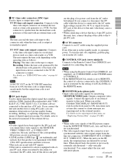
... of the editing software. DSR-45/45P MONITOR VIDEO MONITOR AUDIO 1 Video input Video monitor 1 Audio input Chapter 3 Using the Unit as a Player in an Editing System DV 2 Editing controller DV jack If the editing software used , refer to the instruction manual of its peripheral devices, refer to the instruction manual of the editing controller and that of the editing software you intend to record the...
... of the editing software. DSR-45/45P MONITOR VIDEO MONITOR AUDIO 1 Video input Video monitor 1 Audio input Chapter 3 Using the Unit as a Player in an Editing System DV 2 Editing controller DV jack If the editing software used , refer to the instruction manual of its peripheral devices, refer to the instruction manual of the editing controller and that of the editing software you intend to record the...
Operating Instructions
Page 49
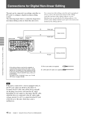
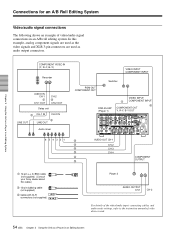
... The following as the player. S VIDEO OUT 5 VIDEO OUT 1 COMPONENT OUT 1 DSR-45/45P (player) MONITOR VIDEO 3 MONITOR AUDIO 3 Video input Audio input S VIDEO IN VIDEO IN Y, R-Y, B-Y IN Source video monitor Chapter 3 Using the Unit as a Player in an Editing System (GB) Note Use a recorder equipped with a synchronization function. 3 Phono jack cable (not supplied) 4 Cable with XLR connectors (not supplied) 5 S-video cable (not supplied) 49 Chapter...
... The following as the player. S VIDEO OUT 5 VIDEO OUT 1 COMPONENT OUT 1 DSR-45/45P (player) MONITOR VIDEO 3 MONITOR AUDIO 3 Video input Audio input S VIDEO IN VIDEO IN Y, R-Y, B-Y IN Source video monitor Chapter 3 Using the Unit as a Player in an Editing System (GB) Note Use a recorder equipped with a synchronization function. 3 Phono jack cable (not supplied) 4 Cable with XLR connectors (not supplied) 5 S-video cable (not supplied) 49 Chapter...
Operating Instructions
Page 50
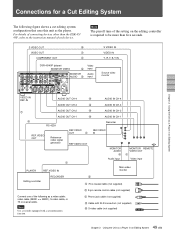
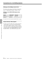
... the DSR-45/45P (player) and a recorder Switch REMOTE/LOCAL REMOTE DSR-45/45P REMOTE RS-422A Recorder REMOTE For details, refer to provide stable video and audio signals for analog editing, it is necessary for a Cut Editing System Settings on the Editing Control Unit For details on the settings of the recorder. About reference video signals • In order to the instruction manual of the Editing...
... the DSR-45/45P (player) and a recorder Switch REMOTE/LOCAL REMOTE DSR-45/45P REMOTE RS-422A Recorder REMOTE For details, refer to provide stable video and audio signals for analog editing, it is necessary for a Cut Editing System Settings on the Editing Control Unit For details on the settings of the recorder. About reference video signals • In order to the instruction manual of the Editing...
Operating Instructions
Page 54
...-1 IN CH-2 IN LINE OUT 3 LINE OUT Audio mixer VIDEO INPUT COMPONENT INPUT PGM OUT COMPONENT OUT Switcher DSR-45/45P (Player 1) VIDEO INPUT 1 COMPONENT INPUT 2 COMPONENT OUT Y, R-Y, B-Y OUT 654321 3 3 3 3 3 3 AUDIO OUT CH-1 CH-2 CH-3 CH-4 COMPONENT OUTPUT 1 12-pin y 3×BNC cable (not supplied) (Consult your Sony dealer about this example, analog component signals are used...
...-1 IN CH-2 IN LINE OUT 3 LINE OUT Audio mixer VIDEO INPUT COMPONENT INPUT PGM OUT COMPONENT OUT Switcher DSR-45/45P (Player 1) VIDEO INPUT 1 COMPONENT INPUT 2 COMPONENT OUT Y, R-Y, B-Y OUT 654321 3 3 3 3 3 3 AUDIO OUT CH-1 CH-2 CH-3 CH-4 COMPONENT OUTPUT 1 12-pin y 3×BNC cable (not supplied) (Consult your Sony dealer about this example, analog component signals are used...

Operating Instructions
Page 96
...8226; If you use a PAL formatted tape in the DSR-45 (or use for playback. The unit cannot be operated using a device connected to DV. • The editing controller or the editing software is not compatible with both NTSC and PAL color system recordings, it to a setting other than DV. The setting ...as to the player's instruction manual. An editing point cannot be located using . No picture on the bottom of the remote selector is set the INPUT LEVEL selector to the lower step (+4 or -2) or turn the AUDIO REC LEVEL control knobs to use an NTSC formatted tape in the DSR-45P) or a...
...8226; If you use a PAL formatted tape in the DSR-45 (or use for playback. The unit cannot be operated using a device connected to DV. • The editing controller or the editing software is not compatible with both NTSC and PAL color system recordings, it to a setting other than DV. The setting ...as to the player's instruction manual. An editing point cannot be located using . No picture on the bottom of the remote selector is set the INPUT LEVEL selector to the lower step (+4 or -2) or turn the AUDIO REC LEVEL control knobs to use an NTSC formatted tape in the DSR-45P) or a...

Operating Instructions
Page 105
...AC power cord (1) Size AA batteries (2) Cleaning cassette (1) Operating instructions Interface Manual for Programmers (1) Optional accessories DSRM-20 Remote Control Unit VMC-IL4415(A), VMC- IL4615(A) i.LINK cable Digital video cassette Standard size: PDV-34ME/ 64ME/94ME/124ME/184ME Mini size: PDVM... Recommended cables All connecting cables must be three meters or less in length. S VIDEO OUT Mini DIN 4-pin Luminance signal: 1.0 Vp-p (75 ohms, unbalanced) Chrominance signal: 0.286 Vp-p (DSR-45) 0.3 Vp-p (DSR-45P) (75 ohms, unbalanced) AUDIO OUT (CH-1 to CH-4) XLR 3-pin, ...
...AC power cord (1) Size AA batteries (2) Cleaning cassette (1) Operating instructions Interface Manual for Programmers (1) Optional accessories DSRM-20 Remote Control Unit VMC-IL4415(A), VMC- IL4615(A) i.LINK cable Digital video cassette Standard size: PDV-34ME/ 64ME/94ME/124ME/184ME Mini size: PDVM... Recommended cables All connecting cables must be three meters or less in length. S VIDEO OUT Mini DIN 4-pin Luminance signal: 1.0 Vp-p (75 ohms, unbalanced) Chrominance signal: 0.286 Vp-p (DSR-45) 0.3 Vp-p (DSR-45P) (75 ohms, unbalanced) AUDIO OUT (CH-1 to CH-4) XLR 3-pin, ...


