Operating Instructions
Page 3
... of Conformity Trade Name: Model: Responsible Party: Address: Telephone Number: SONY DSR-45 Sony Electronics Inc. 680 Kinderkamack Road, Oradell, NJ 07649 USA 201-930-6972 This device complies with Part 15 of the FCC Rules. However, there is connected. • Consult the dealer or an experienced radio/TV technician for a Class B digital device, pursuant to operate this recorder with cable television transmission may require authorization...
... of Conformity Trade Name: Model: Responsible Party: Address: Telephone Number: SONY DSR-45 Sony Electronics Inc. 680 Kinderkamack Road, Oradell, NJ 07649 USA 201-930-6972 This device complies with Part 15 of the FCC Rules. However, there is connected. • Consult the dealer or an experienced radio/TV technician for a Class B digital device, pursuant to operate this recorder with cable television transmission may require authorization...

Operating Instructions
Page 6
... a Player in an Editing System Features 9 (GB) DVCAM Format 9 (GB) Other Features 11 (GB) Location and Function of Parts 12 (GB) Front Panel 12 (GB) Rear Panel 20 (GB) Supplied Remote Commander 25 (GB) Displaying Various Data 27 (GB) Notes on Video Cassettes 30 (GB) Inserting/Ejecting Cassettes 31 (GB) Notes on Playback/Recording 32 (GB) Playback 33 (GB) Connections for Playback 33 (GB) Settings for Playback 35 (GB) Playback Procedures 35 (GB) Playback Functions 36...
... a Player in an Editing System Features 9 (GB) DVCAM Format 9 (GB) Other Features 11 (GB) Location and Function of Parts 12 (GB) Front Panel 12 (GB) Rear Panel 20 (GB) Supplied Remote Commander 25 (GB) Displaying Various Data 27 (GB) Notes on Video Cassettes 30 (GB) Inserting/Ejecting Cassettes 31 (GB) Notes on Playback/Recording 32 (GB) Playback 33 (GB) Connections for Playback 33 (GB) Settings for Playback 35 (GB) Playback Procedures 35 (GB) Playback Functions 36...
Operating Instructions
Page 10
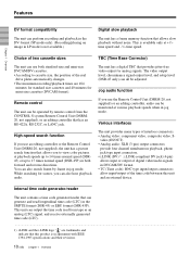
... four channel simultaneous playback, phono jack type input connectors. • i.LINK (DV) 1) : i.LINK-compliant DV jack (4-pin) allows input or output of digital video/audio signals in DVCAM/DV format. • TC (Time code): BNC type input/output connectors allow input/output of the reel drive plates automatically changes. • The maximum recording/playback times are trademarks and indicate that allows you use an editing controller or the Remote Control Unit (DSRM-20, not supplied), the unit has a picture search function...
... four channel simultaneous playback, phono jack type input connectors. • i.LINK (DV) 1) : i.LINK-compliant DV jack (4-pin) allows input or output of digital video/audio signals in DVCAM/DV format. • TC (Time code): BNC type input/output connectors allow input/output of the reel drive plates automatically changes. • The maximum recording/playback times are trademarks and indicate that allows you use an editing controller or the Remote Control Unit (DSRM-20, not supplied), the unit has a picture search function...

Operating Instructions
Page 19
... unit plays back a part of seven digits. Notes • In the playback mode, if the tape has a portion where recorded signals are displayed with cassette memory, the end search function works even if you can easily find the scene later. Use this button, the unit searches the tape and plays back the last five-second recorded picture. You cannot make the counter operate on the VTR SET menu is inside of the displayed time code...
... unit plays back a part of seven digits. Notes • In the playback mode, if the tape has a portion where recorded signals are displayed with cassette memory, the end search function works even if you can easily find the scene later. Use this button, the unit searches the tape and plays back the last five-second recorded picture. You cannot make the counter operate on the VTR SET menu is inside of the displayed time code...
Operating Instructions
Page 20
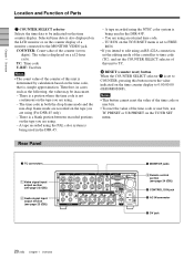
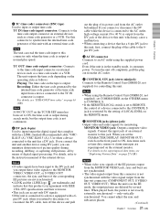
... a portion where the time code is set the COUNTER SELECT selector of this button resets the value indicated on the TC/UB SET menu. Rear Panel 1 TC connectors 1 Video signal input/ output section (see page 22 (GB)) 2 Audio signal input/ output section (see page 23 (GB)) 5 MONITOR jacks 3 Remote control section (see page 24 (GB)) 4 CONTROL S IN jack 3 AC IN connector 2 DV jack 20 (GB) Chapter 1 Overview A tape recorded using . - A tape recorded using the PAL color system is being...
... a portion where the time code is set the COUNTER SELECT selector of this button resets the value indicated on the TC/UB SET menu. Rear Panel 1 TC connectors 1 Video signal input/ output section (see page 22 (GB)) 2 Audio signal input/ output section (see page 23 (GB)) 5 MONITOR jacks 3 Remote control section (see page 24 (GB)) 4 CONTROL S IN jack 3 AC IN connector 2 DV jack 20 (GB) Chapter 1 Overview A tape recorded using . - A tape recorded using the PAL color system is being...
Operating Instructions
Page 21
... superimposed data items, see "DSR-45/45P time codes" on the external monitor. only vertically synchronized. TC IN (time code input) connector: Connects to the CONTROL S jack is restricted by several lines. The unit outputs the time code depending on the operating state as follows: Playing: The time code on the TC/UB SET menu has been set to REMOTE, the control of a device connected to the time code output connector on the REMOTE menu. 5 MONITOR jacks (phono jack) Output video and audio signals for controlling...
... superimposed data items, see "DSR-45/45P time codes" on the external monitor. only vertically synchronized. TC IN (time code input) connector: Connects to the CONTROL S jack is restricted by several lines. The unit outputs the time code depending on the operating state as follows: Playing: The time code on the TC/UB SET menu has been set to REMOTE, the control of a device connected to the time code output connector on the REMOTE menu. 5 MONITOR jacks (phono jack) Output video and audio signals for controlling...
Operating Instructions
Page 22
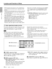
... some home game machines • Blue background screen or gray background screen from a consumer VCR • Pictures played at a speed other than normal by a VCR that does not have the TBC (Time Base Corrector) • Video signals in the EE mode, depending on the monitor. • The data items superimposed on a monitor connected to 4 CH-3/4: channels 3/4 1 Video signal input/output section For details on the input and output of PB LEVEL on the VIDEO SET menu...
... some home game machines • Blue background screen or gray background screen from a consumer VCR • Pictures played at a speed other than normal by a VCR that does not have the TBC (Time Base Corrector) • Video signals in the EE mode, depending on the monitor. • The data items superimposed on a monitor connected to 4 CH-3/4: channels 3/4 1 Video signal input/output section For details on the input and output of PB LEVEL on the VIDEO SET menu...
Operating Instructions
Page 32
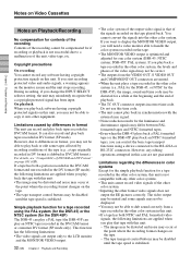
... video signals are output only to play back or edit some signals may not be displayed. • You may mistakenly recognize that a copyright protected signal has been input. DSR-45P: PAL system). If you can control the basic tape transport functions using the PAL system (for the DSR-45) or the NTSC system (for a tape recorded in synchronization with this case are applied when you start recording protected video and audio signals, a warning appears on the monitor screen...
... video signals are output only to play back or edit some signals may not be displayed. • You may mistakenly recognize that a copyright protected signal has been input. DSR-45P: PAL system). If you can control the basic tape transport functions using the PAL system (for the DSR-45) or the NTSC system (for a tape recorded in synchronization with this case are applied when you start recording protected video and audio signals, a warning appears on the monitor screen...
Operating Instructions
Page 33
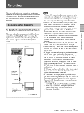
... detected so you play back a recorded tape on this unit and press the DATA CODE button on the monitor screen. • The external lock function of an editing system, for Playback To digital video equipment with a DV jack The video and audio signals are displayed on the Remote Commander, the same data codes as a stand-alone videocassette player. Disconnect the cables. Digital video equipment with hardly any degradation, enabling high-quality recording. The same settings and operations apply whether you...
... detected so you play back a recorded tape on this unit and press the DATA CODE button on the monitor screen. • The external lock function of an editing system, for Playback To digital video equipment with a DV jack The video and audio signals are displayed on the Remote Commander, the same data codes as a stand-alone videocassette player. Disconnect the cables. Digital video equipment with hardly any degradation, enabling high-quality recording. The same settings and operations apply whether you...

Operating Instructions
Page 35
... the cables. • Text data (time code, warnings, menus, etc.) are superimposed only on the MONITOR VIDEO output. • To play back in the SP mode of the DV format. 35 Chapter 2 Playback and Recording (GB) Playback Procedures This section describes the procedures used to play back only tapes recorded in the DVCAM format or in synchronization with the reference video (black burst) signal, set the monitor's input switch according to the instruction manual of your...
... the cables. • Text data (time code, warnings, menus, etc.) are superimposed only on the MONITOR VIDEO output. • To play back in the SP mode of the DV format. 35 Chapter 2 Playback and Recording (GB) Playback Procedures This section describes the procedures used to play back only tapes recorded in the DVCAM format or in synchronization with the reference video (black burst) signal, set the monitor's input switch according to the instruction manual of your...
Operating Instructions
Page 41
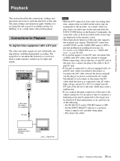
... displayed on the source tape are transmitted to the input connectors of a player or that of a monitor, a humming noise may be generated or the image may be distorted. Monitor DSR-45/45P (rear panel) i.LINK cable (DV cable) (not supplied) DV jack Digital video equipment with a DV jack Monitor : Signal flow Notes • With the DV connection, the sound is recorded in a different audio recording mode from the source tape, use the duplicate function. • If no picture...
... displayed on the source tape are transmitted to the input connectors of a player or that of a monitor, a humming noise may be generated or the image may be distorted. Monitor DSR-45/45P (rear panel) i.LINK cable (DV cable) (not supplied) DV jack Digital video equipment with a DV jack Monitor : Signal flow Notes • With the DV connection, the sound is recorded in a different audio recording mode from the source tape, use the duplicate function. • If no picture...
Operating Instructions
Page 59
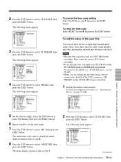
... IN TC V TC MAKE A TC RUN VTR TC FORMAT ETC JOG TC OUT Chapter 4 Setting the Time Code and Adjusting the Video Signals 5 Set the first two digits. The following menu appears. Notes • The user bits can set the user bits, you are setting the user bits using a device connected to select TC PRESET, then press the EXEC button. The following menu appears. TC ⁄ UB SET TC TC PRESET RMT...
... IN TC V TC MAKE A TC RUN VTR TC FORMAT ETC JOG TC OUT Chapter 4 Setting the Time Code and Adjusting the Video Signals 5 Set the first two digits. The following menu appears. Notes • The user bits can set the user bits, you are setting the user bits using a device connected to select TC PRESET, then press the EXEC button. The following menu appears. TC ⁄ UB SET TC TC PRESET RMT...
Operating Instructions
Page 61
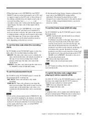
... a DV format recording, the drop-frame mode is used to set the current time as time code. To set the time code when the recording starts Set TC MAKE on the TC/UB SET menu to select the time code to be updated by the internal clock while the unit's power is off. To switch the time code output when playing at normal speed. Chapter 4 Setting the Time Code and Adjusting the Video Signals • When this item is set to EXTERNAL, the INPUT SELECT...
... a DV format recording, the drop-frame mode is used to set the current time as time code. To set the time code when the recording starts Set TC MAKE on the TC/UB SET menu to select the time code to be updated by the internal clock while the unit's power is off. To switch the time code output when playing at normal speed. Chapter 4 Setting the Time Code and Adjusting the Video Signals • When this item is set to EXTERNAL, the INPUT SELECT...

Operating Instructions
Page 72
... MODE on the LCD monitor and the MONITOR VIDEO output screen. The cassette memory data cannot be displayed on the VTR SET menu of the recorder (this unit) does not have cassette memory, but the recorder tried to the instruction manual of the tape. The recorder (this unit. Connect only one player to DVCAM. The DV cable has been unplugged and plugged in the recording mode. There are multiple DV connections or the DV connection is set to...
... MODE on the LCD monitor and the MONITOR VIDEO output screen. The cassette memory data cannot be displayed on the VTR SET menu of the recorder (this unit) does not have cassette memory, but the recorder tried to the instruction manual of the tape. The recorder (this unit. Connect only one player to DVCAM. The DV cable has been unplugged and plugged in the recording mode. There are multiple DV connections or the DV connection is set to...
Operating Instructions
Page 79
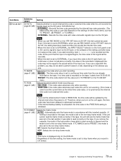
... problem, you use the frame mode that is initialized. Even if this item setting, the frame mode is set to drop frame when you record in DVCAM format. TC MAKE Selects the time code when you start recording. (page 61 (GB)) REGEN : The time code value is input via the DV jack, or the software of the recorded or displayed time code may not be used to FREE RUN, the time code will use a tape with video and audio signals input...
... problem, you use the frame mode that is initialized. Even if this item setting, the frame mode is set to drop frame when you record in DVCAM format. TC MAKE Selects the time code when you start recording. (page 61 (GB)) REGEN : The time code value is input via the DV jack, or the software of the recorded or displayed time code may not be used to FREE RUN, the time code will use a tape with video and audio signals input...

Operating Instructions
Page 85
... not use the color bars output from those of the the input image input sound DUP button Image input to the DV jack AUDIO Mute screen DUB button (black) Sound input to display the data codes on the LCD monitor or MONITOR VIDEO output. • If you press any of the REC, DUP, or AUDIO DUB buttons separately when the unit is stopped (unless the cassette has been write-protected). DISPLAY SET menu Icon/Menu DISP DISPLAY SET Submenu (page) Setting DATA CODE...
... not use the color bars output from those of the the input image input sound DUP button Image input to the DV jack AUDIO Mute screen DUB button (black) Sound input to display the data codes on the LCD monitor or MONITOR VIDEO output. • If you press any of the REC, DUP, or AUDIO DUB buttons separately when the unit is stopped (unless the cassette has been write-protected). DISPLAY SET menu Icon/Menu DISP DISPLAY SET Submenu (page) Setting DATA CODE...

Operating Instructions
Page 87
... factory preset values.) • The SETUP default is displayed in the externally-synchronized playback mode. • If you change this item only in the composite signals. Chapter 6 Adjusting and Setting Through Menus (Continued) 87 Chapter 6 Adjusting and Setting Through Menus (GB) The setup level for the DSR-45. Set this item is set SETUP at 0% and if you play back a 7.5% tape, the tape will be played at 7.5%. (You cannot play back a 7.5% tape at the 7.5% setting...
... factory preset values.) • The SETUP default is displayed in the externally-synchronized playback mode. • If you change this item only in the composite signals. Chapter 6 Adjusting and Setting Through Menus (Continued) 87 Chapter 6 Adjusting and Setting Through Menus (GB) The setup level for the DSR-45. Set this item is set SETUP at 0% and if you play back a 7.5% tape, the tape will be played at 7.5%. (You cannot play back a 7.5% tape at the 7.5% setting...

Operating Instructions
Page 90
... the DVCAM format. Set REC MODE to use a tape recorded in the SP mode of these two recorded portions, picture and sound may be automatically switched; AUTO INDEX Selects whether or not the unit automatically marks an index signal when the unit in DVCAM format. However, if you intend to edit using an RS-422A connection, set to lock mode sound.) - The unit records internal time code. • If you do not need to DV...
... the DVCAM format. Set REC MODE to use a tape recorded in the SP mode of these two recorded portions, picture and sound may be automatically switched; AUTO INDEX Selects whether or not the unit automatically marks an index signal when the unit in DVCAM format. However, if you intend to edit using an RS-422A connection, set to lock mode sound.) - The unit records internal time code. • If you do not need to DV...

Operating Instructions
Page 94
... set to dub the sound onto a DV-formatted tape. You have set TC MAKE to DV. To prevent this unit are correct, you have pulled out the plug of the power cord from the digital non-linear editing controller does not include a time code. COMMANDER on the OTHERS menu is set to WIRELESS and a Sony Remote Commander whose command mode is set to the device used. t Change the setting of the input DV signal is not recorded. The edit timing...
... set to dub the sound onto a DV-formatted tape. You have set TC MAKE to DV. To prevent this unit are correct, you have pulled out the plug of the power cord from the digital non-linear editing controller does not include a time code. COMMANDER on the OTHERS menu is set to WIRELESS and a Sony Remote Commander whose command mode is set to the device used. t Change the setting of the input DV signal is not recorded. The edit timing...

Operating Instructions
Page 106
... component signals. Using this mode. PCM audio PCM stands for recording or playback, so a still picture can check the input signals and adjust the input level in synchronization with a reference signal during playback and recording so that are output via only the electric circuit by broadcasting and related organizations in the same pattern during recording and playback. Each analog audio signal is converted into pulses that the video heads scan the tape in USA. Servo lock...
... component signals. Using this mode. PCM audio PCM stands for recording or playback, so a still picture can check the input signals and adjust the input level in synchronization with a reference signal during playback and recording so that are output via only the electric circuit by broadcasting and related organizations in the same pattern during recording and playback. Each analog audio signal is converted into pulses that the video heads scan the tape in USA. Servo lock...


