Operating Instructions (primary manual)
Page 2
...mement basses (ELF). Owner's Record The model and serial numbers are located at the rear of Conformity Trade Name: Sony Model No.: CPD-M151 Responsible Party: Sony Electronics Inc. Dangerously high voltages are designed to which can radiate radio frequency energy and, if not installed and used...237;a (MPR) emitidas en diciembre de 1990 (MPR II) para frecuencias muy bajas (VLF) y frecuencias extremadamente bajas (ELF). This monitor complies with Part 15 of the FCC Rules. der Darstellung eines Buchstabens zur Deckung (Konvergenz) gelangen. Siehe hierzu auch die Erklä...
...mement basses (ELF). Owner's Record The model and serial numbers are located at the rear of Conformity Trade Name: Sony Model No.: CPD-M151 Responsible Party: Sony Electronics Inc. Dangerously high voltages are designed to which can radiate radio frequency energy and, if not installed and used...237;a (MPR) emitidas en diciembre de 1990 (MPR II) para frecuencias muy bajas (VLF) y frecuencias extremadamente bajas (ELF). This monitor complies with Part 15 of the FCC Rules. der Darstellung eines Buchstabens zur Deckung (Konvergenz) gelangen. Siehe hierzu auch die Erklä...
Operating Instructions (primary manual)
Page 3
... Computer, Inc., registered in this manual. 3 S. TABLE OF CONTENTS Getting Started Getting Started Precautions ...4 Identifying Parts and Controls 5 Setup ...6 Turning on the Monitor and Computer 10 Customizing Your Monitor Introducing the On-Screen Display System 11 Selecting the On-Screen Display Language 11 Automatically Adjusting the Picture 12 Eliminating Flickering or Blurring...
... Computer, Inc., registered in this manual. 3 S. TABLE OF CONTENTS Getting Started Getting Started Precautions ...4 Identifying Parts and Controls 5 Setup ...6 Turning on the Monitor and Computer 10 Customizing Your Monitor Introducing the On-Screen Display System 11 Selecting the On-Screen Display Language 11 Automatically Adjusting the Picture 12 Eliminating Flickering or Blurring...
Operating Instructions (primary manual)
Page 4
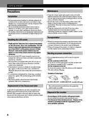
...additive as a transformer or high voltage power lines. Consult your local power supply. If you transport this monitor for your Sony dealer when replacing the fluorescent tube. Disposal of the monitor • Do not dispose of the picture element is installed as it can damage the LCD screen. ...When the monitor becomes warm, the screen returns to 240 V AC for a long time, a residual image may appear constantly. &#...
...additive as a transformer or high voltage power lines. Consult your local power supply. If you transport this monitor for your Sony dealer when replacing the fluorescent tube. Disposal of the monitor • Do not dispose of the picture element is installed as it can damage the LCD screen. ...When the monitor becomes warm, the screen returns to 240 V AC for a long time, a residual image may appear constantly. &#...
Operating Instructions (primary manual)
Page 5
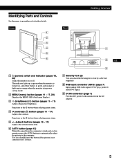
...adjust the picture to the monitor from the AC adaptor. supplied). Adjusts the picture brightness. Front Rear 1 2 3 4 7 5 6 8 GB F 9 D 1 u (power) switch and indicator (pages 10, 7 Security lock ( ) ES 20) You can attach the Kensington's security cable (not Turns the monitor on , and either ...flashes in green and orange or lights up in orange when the monitor is fuzzy. 5 Functions as the ≥ button when selecting menu items. 5 +/- (adjust) buttons ...
...adjust the picture to the monitor from the AC adaptor. supplied). Adjusts the picture brightness. Front Rear 1 2 3 4 7 5 6 8 GB F 9 D 1 u (power) switch and indicator (pages 10, 7 Security lock ( ) ES 20) You can attach the Kensington's security cable (not Turns the monitor on , and either ...flashes in green and orange or lights up in orange when the monitor is fuzzy. 5 Functions as the ≥ button when selecting menu items. 5 +/- (adjust) buttons ...
Operating Instructions (primary manual)
Page 6
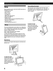
.... To adjust the angle, hold at the bottom with both hands as illustrated. 65° To adjust the angle The tilt feature allows the monitor to be adjusted within 65° upward. The procedure of connecting cables and attaching the rear cover differs depending on page 8. The rear cover...at the bottom and open the stand as illustrated. 6 however, the connector to the computer and power source. Getting Started Setup Before using this monitor, check that the following items are the same even when the stand is explained using the stand-type set up without the stand. Stand set...
.... To adjust the angle, hold at the bottom with both hands as illustrated. 65° To adjust the angle The tilt feature allows the monitor to be adjusted within 65° upward. The procedure of connecting cables and attaching the rear cover differs depending on page 8. The rear cover...at the bottom and open the stand as illustrated. 6 however, the connector to the computer and power source. Getting Started Setup Before using this monitor, check that the following items are the same even when the stand is explained using the stand-type set up without the stand. Stand set...

Operating Instructions (primary manual)
Page 7
... Power Macintosh G3 series computers (sold after January 1999, you are connecting to a power outlet. Step 1: Connect the monitor to the monitor. This adapter is not compatible with micro switches (not supplied). Macintosh II series and some older versions of the power ... PC/AT or compatible computer to a power outlet Power cord (supplied) AC power adapter (supplied) 7 Macintosh or compatible computer to monitor output HD15 video signal cable (supplied) Macintosh adapter (supplied)* * Connect the supplied Macintosh adapter to a Macintosh Use the supplied Macintosh...
... Power Macintosh G3 series computers (sold after January 1999, you are connecting to a power outlet. Step 1: Connect the monitor to the monitor. This adapter is not compatible with micro switches (not supplied). Macintosh II series and some older versions of the power ... PC/AT or compatible computer to a power outlet Power cord (supplied) AC power adapter (supplied) 7 Macintosh or compatible computer to monitor output HD15 video signal cable (supplied) Macintosh adapter (supplied)* * Connect the supplied Macintosh adapter to a Macintosh Use the supplied Macintosh...
Operating Instructions (primary manual)
Page 8
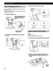
... place under the LCD panel 1 Remove the screws from the fixing shaft of the stand. 2 Place the monitor on the soft cloth with the LCD panel facing down, and pull the stand out from the monitor. 8 Getting Started Step 3: Attaching the rear cover After connecting the computer and power cord, attach the... cover. Align the marking tape of the AC adapter cord 2 Press the rear cover against the part for attaching the cover. Unlocked Locked Using the monitor without the stand Prepare: Philip's screw driver Soft cloth to fasten the rear cover.
... place under the LCD panel 1 Remove the screws from the fixing shaft of the stand. 2 Place the monitor on the soft cloth with the LCD panel facing down, and pull the stand out from the monitor. 8 Getting Started Step 3: Attaching the rear cover After connecting the computer and power cord, attach the... cover. Align the marking tape of the AC adapter cord 2 Press the rear cover against the part for attaching the cover. Unlocked Locked Using the monitor without the stand Prepare: Philip's screw driver Soft cloth to fasten the rear cover.
Operating Instructions (primary manual)
Page 9
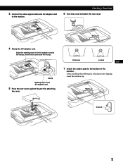
Align the marking tape of the F monitor. ES I Peel off 9 Getting StarGteedtting Started 6 Turn the screw to the monitor. Unlocked Locked GB 7 Attach the rubber pads to the bottom of the AC adapter cord to the clamp, wind it once and close the clamp. D After attaching the rubberpads, which prevent slipping, stand the monitor up. Clamp Marking tape of the AC adapter cord 5 Press the rear cover against the part for attaching the cover. 3 Connect the video signal cable and AC adapter cord to fasten the rear cover. 4 Clamp the AC adapter cord.
Align the marking tape of the F monitor. ES I Peel off 9 Getting StarGteedtting Started 6 Turn the screw to the monitor. Unlocked Locked GB 7 Attach the rubber pads to the bottom of the AC adapter cord to the clamp, wind it once and close the clamp. D After attaching the rubberpads, which prevent slipping, stand the monitor up. Clamp Marking tape of the AC adapter cord 5 Press the rear cover against the part for attaching the cover. 3 Connect the video signal cable and AC adapter cord to fasten the rear cover. 4 Clamp the AC adapter cord.
Operating Instructions (primary manual)
Page 10
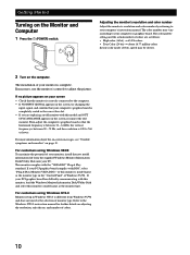
... symptoms and remedies" on the screen, reconnect the old monitor. This monitor complies with DDC, select "Plug & Play Monitor (VESA DDC)" or this monitor's model name as the monitor type in Windows NT4.0 is different from the supplied Windows Monitor Information Disk/Utility Disk onto your computer or graphics board....If no picture appears on adjusting the resolution, refresh rate, and number of Windows 95/98. If your screen • Check that the monitor is 1024 x 768 or lower. Refer to the computer. • If NO INPUT SIGNAL appears on the screen, try changing the input...
... symptoms and remedies" on the screen, reconnect the old monitor. This monitor complies with DDC, select "Plug & Play Monitor (VESA DDC)" or this monitor's model name as the monitor type in Windows NT4.0 is different from the supplied Windows Monitor Information Disk/Utility Disk onto your computer or graphics board....If no picture appears on adjusting the resolution, refresh rate, and number of Windows 95/98. If your screen • Check that the monitor is 1024 x 768 or lower. Refer to the computer. • If NO INPUT SIGNAL appears on the screen, try changing the input...

Operating Instructions (primary manual)
Page 11
... English, French, German, Spanish, Italian, and Japanese. 1 Press the MENU button. PHASE Displays the PHASE OSD. The MENU OSD appears. Customizing Your Monitor GCeuttsitnogmSiztianrgteYdour Monitor Before adjusting Connect the monitor and the computer, and turn them on -screen display language, see "Selecting the On-Screen Display Language." MENU MENU OK MENU EXIT PHASE...
... English, French, German, Spanish, Italian, and Japanese. 1 Press the MENU button. PHASE Displays the PHASE OSD. The MENU OSD appears. Customizing Your Monitor GCeuttsitnogmSiztianrgteYdour Monitor Before adjusting Connect the monitor and the computer, and turn them on -screen display language, see "Selecting the On-Screen Display Language." MENU MENU OK MENU EXIT PHASE...
Operating Instructions (primary manual)
Page 12
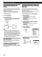
...PITCH CENTER COLOR LANGUAGE OPTION 5 Press the ˘/≥ buttons to 1024 × 768 on the computer. 3 Press the AUTO button. The monitor adjusts the pitch to match the input signal so that provides a full-screen picture. This is flickering or fuzzy, press the AUTO button. For... on the computer. 2 Load the Utility Disk. The monitor is dark or if the input picture does not fill the screen to "Eliminating Flickering or Blurring Manually." For Macintosh Click [Utility Disk] n [SONY-Utility]. 4 Press the MENU button. In this operation does not work properly if the ...
...PITCH CENTER COLOR LANGUAGE OPTION 5 Press the ˘/≥ buttons to 1024 × 768 on the computer. 3 Press the AUTO button. The monitor adjusts the pitch to match the input signal so that provides a full-screen picture. This is flickering or fuzzy, press the AUTO button. For... on the computer. 2 Load the Utility Disk. The monitor is dark or if the input picture does not fill the screen to "Eliminating Flickering or Blurring Manually." For Macintosh Click [Utility Disk] n [SONY-Utility]. 4 Press the MENU button. In this operation does not work properly if the ...

Operating Instructions (primary manual)
Page 13
... "Eliminating Flickering or Blurring Manually." 2 Press the MENU button. If this operation does not work, adjust the centering as follows. The CENTER OSD appears. GCeuttsitnogmSiztianrgteYdour Monitor Adjusting the Picture Position If the picture is adjusted, it will be stored in the center of the screen, press the AUTO button. The OSD...
... "Eliminating Flickering or Blurring Manually." 2 Press the MENU button. If this operation does not work, adjust the centering as follows. The CENTER OSD appears. GCeuttsitnogmSiztianrgteYdour Monitor Adjusting the Picture Position If the picture is adjusted, it will be stored in the center of the screen, press the AUTO button. The OSD...

Operating Instructions (primary manual)
Page 14
.... 1 Press the MENU button. MENU MENU OK MENU EXIT PHASE PITCH CENTER COLOR LANGUAGE OPTION 14 Customizing Your Monitor For vertical adjustment, select V using the ˘/≥ buttons and adjust the position using the monitor in a dark room Decrease the BACKLIGHT (page 16). to 9300K at the factory. To close the OSD...
.... 1 Press the MENU button. MENU MENU OK MENU EXIT PHASE PITCH CENTER COLOR LANGUAGE OPTION 14 Customizing Your Monitor For vertical adjustment, select V using the ˘/≥ buttons and adjust the position using the monitor in a dark room Decrease the BACKLIGHT (page 16). to 9300K at the factory. To close the OSD...

Operating Instructions (primary manual)
Page 15
... press the MENU button again. 2 Press the ˘/≥ buttons to the desired position. COLOR MENU 9300K 6500K 5000K USER MODE R 50 G 50 B 50 GCeuttsitnogmSiztianrgteYdour Monitor 2 Press the ˘/≥ buttons to step 4. COLOR 9300K 6500K 5000K USER MODE R 50 G 50 B 50 The OSD automatically disappears after about 30 seconds. If...
... press the MENU button again. 2 Press the ˘/≥ buttons to the desired position. COLOR MENU 9300K 6500K 5000K USER MODE R 50 G 50 B 50 GCeuttsitnogmSiztianrgteYdour Monitor 2 Press the ˘/≥ buttons to step 4. COLOR 9300K 6500K 5000K USER MODE R 50 G 50 B 50 The OSD automatically disappears after about 30 seconds. If...

Operating Instructions (primary manual)
Page 16
...The MENU OSD appears. See page 18 for more information on this monitor's power saving capabilities. 1 Press the MENU button. When PWR SAVE DELAY is too bright when you are ...using the monitor in a dark room, adjust the backlight. 1 Press the MENU button. The OPTION OSD ... buttons to select ZZ... (PWR SAVE DELAY). Setting the Power Saving Delay Time You can set to OFF, the monitor does not go into power saving mode. The OPTION OSD appears. OPTION MENU : 5SEC : UNLOCK OSD H POSITION ...
...The MENU OSD appears. See page 18 for more information on this monitor's power saving capabilities. 1 Press the MENU button. When PWR SAVE DELAY is too bright when you are ...using the monitor in a dark room, adjust the backlight. 1 Press the MENU button. The OPTION OSD ... buttons to select ZZ... (PWR SAVE DELAY). Setting the Power Saving Delay Time You can set to OFF, the monitor does not go into power saving mode. The OPTION OSD appears. OPTION MENU : 5SEC : UNLOCK OSD H POSITION ...

Operating Instructions (primary manual)
Page 17
... you select "LOCK," you press any locked button, the the screen. mark appears on -screen language, however, does not change. 1 Press the MENU button. GCeuttsitnogmSiztianrgteYdour Monitor To cancel the control lock Press the + button in the OPTION OSD If you can reset all of the adjustments and settings to select OPTION...
... you select "LOCK," you press any locked button, the the screen. mark appears on -screen language, however, does not change. 1 Press the MENU button. GCeuttsitnogmSiztianrgteYdour Monitor To cancel the control lock Press the + button in the OPTION OSD If you can reset all of the adjustments and settings to select OPTION...
Operating Instructions (primary manual)
Page 18
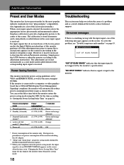
...the Environmental Protection Agency. *** When your computer enters the power saving mode, the input signal is stored in parentheses are power consumption of the monitor including the AC adapter. ** "Sleep" and "deep sleep" are stored automatically as the more stringent NUTEK . The calibration is cut and... NO INPUT SIGNAL appears on the screen. On-screen messages If there is input to the monitor. * Power consumption of the monitor only. INFORMATION OUT OF SCAN RANGE "OUT OF SCAN RANGE" indicates that no signal is something wrong with the input ...
...the Environmental Protection Agency. *** When your computer enters the power saving mode, the input signal is stored in parentheses are power consumption of the monitor including the AC adapter. ** "Sleep" and "deep sleep" are stored automatically as the more stringent NUTEK . The calibration is cut and... NO INPUT SIGNAL appears on the screen. On-screen messages If there is input to the monitor. * Power consumption of the monitor only. INFORMATION OUT OF SCAN RANGE "OUT OF SCAN RANGE" indicates that no signal is something wrong with the input ...
Operating Instructions (primary manual)
Page 19
...M151" from power lines or place a magnetic shield near the monitor. • Try plugging the monitor into a different AC outlet, preferably on a different circuit. • Try turning the monitor...monitor with this monitor (Appendix). p Problems caused by the connected computer or other monitors, laser printers, electric fans, fluorescent lighting, or televisions. • Move the monitor away from among the Sony monitors... . Install the Windows Monitor Information Disk/Utility Disk and select "CPD- If this monitor, reconnect the old monitor and do the following recommendations...
...M151" from power lines or place a magnetic shield near the monitor. • Try plugging the monitor into a different AC outlet, preferably on a different circuit. • Try turning the monitor...monitor with this monitor (Appendix). p Problems caused by the connected computer or other monitors, laser printers, electric fans, fluorescent lighting, or televisions. • Move the monitor away from among the Sony monitors... . Install the Windows Monitor Information Disk/Utility Disk and select "CPD- If this monitor, reconnect the old monitor and do the following recommendations...
Operating Instructions (primary manual)
Page 20
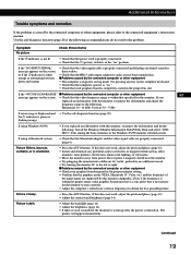
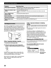
...page 12). Press and hold the MENU button for 2 seconds. Color is a potential monitor failure. Example INFORMATION MODEL : CPD-M151 SER NO : 1234567 MANUFACTURED : 1999-52 Model name Serial number Week and year of the monitor's condition. If the u(power) indicator is lit in power saving mode. u (power...the make and model of your computer. Note that all four color bars appear (white, red, green, blue), the monitor is a problem with your authorized Sony dealer of video cable extensions and/or video switch boxes. • Check that some video modes do not operate. &#...
...page 12). Press and hold the MENU button for 2 seconds. Color is a potential monitor failure. Example INFORMATION MODEL : CPD-M151 SER NO : 1234567 MANUFACTURED : 1999-52 Model name Serial number Week and year of the monitor's condition. If the u(power) indicator is lit in power saving mode. u (power...the make and model of your computer. Note that all four color bars appear (white, red, green, blue), the monitor is a problem with your authorized Sony dealer of video cable extensions and/or video switch boxes. • Check that some video modes do not operate. &#...
Operating Instructions (primary manual)
Page 21
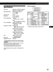
...: 50 - 75 Hz 99.99 % H: max. 1024 dots V: max. 768 lines Operation: AC 100 - 240 V, 50 - 60 Hz Input: DC 12 V (using the AC adapter) Monitor only: Max. 25 W Including the AC adapter: Max. 35 W With the stand: Approx. 395 × 358 × 173 mm (15 5/8 × 14 1/8 × 6 7/8 in.) Without...
...: 50 - 75 Hz 99.99 % H: max. 1024 dots V: max. 768 lines Operation: AC 100 - 240 V, 50 - 60 Hz Input: DC 12 V (using the AC adapter) Monitor only: Max. 25 W Including the AC adapter: Max. 35 W With the stand: Approx. 395 × 358 × 173 mm (15 5/8 × 14 1/8 × 6 7/8 in.) Without...


