Operation Guide
Page 2
... during operation of important operating and maintenance (servicing) instructions in the fixed wiring, or connect the power plug to an easily accessible socket-outlet near any heat sources such as it is intended to alert the user to the presence of uninsulated "dangerous voltage"...Servicing is not suitable for replacement of fire or electric shock, do not open the cabinet. WARNING To reduce the risk of the obsolete outlet. Protect the power cord from tip-over. Unplug this apparatus to switch the power supply off . BVM-E251 only When installing the installation...
... during operation of important operating and maintenance (servicing) instructions in the fixed wiring, or connect the power plug to an easily accessible socket-outlet near any heat sources such as it is intended to alert the user to the presence of uninsulated "dangerous voltage"...Servicing is not suitable for replacement of fire or electric shock, do not open the cabinet. WARNING To reduce the risk of the obsolete outlet. Protect the power cord from tip-over. Unplug this apparatus to switch the power supply off . BVM-E251 only When installing the installation...
Operation Guide
Page 3
... intended for a Class A digital device, pursuant to the proper ratings (Voltage, Ampere). Lower, Upper : 4.4 cm (1 3/4 inches) or more Right, Left : 1.0 cm (13/32 inches) or more of the Operation Manual. 6.When performing the installation, keep the following Electromagnetic Environment: E4 (controlled EMC environment, ex. If used to the specifications of space above Power Cord / Appliance Connector / Plug, please consult a qualified service personnel. To reduce the...
... intended for a Class A digital device, pursuant to the proper ratings (Voltage, Ampere). Lower, Upper : 4.4 cm (1 3/4 inches) or more Right, Left : 1.0 cm (13/32 inches) or more of the Operation Manual. 6.When performing the installation, keep the following Electromagnetic Environment: E4 (controlled EMC environment, ex. If used to the specifications of space above Power Cord / Appliance Connector / Plug, please consult a qualified service personnel. To reduce the...

Operation Guide
Page 5
... Status] Menu 68 [Controller] Menu 70 [Key Protect] Menu 73 Displaying the Monitor Status Page 74 Upgrading the Monitor and Controller ....... 76 Saving the Upgrade Data in the United States and other countries. 5 Table of HDMI Licensing Administrator, Inc. compatibility 82 Connecting the SDI Signals 83 Troubleshooting 84 Specifications 85 BVM-E251 85 BVM-E171 86 Available Signal Formats 88 Aperture Modification Frequency 93 Picture Display Size 94 Picture Frame Display 97 Scan Mode Image 99...
... Status] Menu 68 [Controller] Menu 70 [Key Protect] Menu 73 Displaying the Monitor Status Page 74 Upgrading the Monitor and Controller ....... 76 Saving the Upgrade Data in the United States and other countries. 5 Table of HDMI Licensing Administrator, Inc. compatibility 82 Connecting the SDI Signals 83 Troubleshooting 84 Specifications 85 BVM-E251 85 BVM-E171 86 Available Signal Formats 88 Aperture Modification Frequency 93 Picture Display Size 94 Picture Frame Display 97 Scan Mode Image 99...

Operation Guide
Page 6
...Disconnect the power cord from the wall outlet if it is not to secure the operation area. Connecting to Other Devices When connecting this unit to this unit and the other devices, turn off (black), always on...cord. The socket-outlet shall be installed near the equipment and shall be used for [Gamma] in the [Matrix/Color Profile] menu, images are output. This is installed on (red, green, or blue), or flashing. Be sure to take an occasional break when using. Follow RECOMMENDATION ITU-R BT.1702 "Guidance for extended periods may appear spontaneously. Do not touch...
...Disconnect the power cord from the wall outlet if it is not to secure the operation area. Connecting to Other Devices When connecting this unit to this unit and the other devices, turn off (black), always on...cord. The socket-outlet shall be installed near the equipment and shall be used for [Gamma] in the [Matrix/Color Profile] menu, images are output. This is installed on (red, green, or blue), or flashing. Be sure to take an occasional break when using. Follow RECOMMENDATION ITU-R BT.1702 "Guidance for extended periods may appear spontaneously. Do not touch...

Operation Guide
Page 14
... peripheral device wiring that incorporates coding technology for this port. CAUTION For safety, do not connect the connector for this monitor. Or connect to enter sleep mode when the power switch is turned on the input signal (MONO button function). By setting in the United States and other countries. Note The HDMI audio signal is displayed or the monitor switches the display mode automatically between color image and monochrome image depending on . 14 Location and...
... peripheral device wiring that incorporates coding technology for this port. CAUTION For safety, do not connect the connector for this monitor. Or connect to enter sleep mode when the power switch is turned on the input signal (MONO button function). By setting in the United States and other countries. Note The HDMI audio signal is displayed or the monitor switches the display mode automatically between color image and monochrome image depending on . 14 Location and...

Operation Guide
Page 19
... remove the AC power cord Pull out the AC plug holder while pressing the lock levers. When the AC power cord and DC power supply are connected, the AC power supply is displayed. When you intend to the DC IN 24V - 28V connector. Select the area where you turn on the power. The OPERATE indicator lights in sleep mode, press the MONITOR switch of the controller. To connect the DC power supply Connect the DC power supply to use...
... remove the AC power cord Pull out the AC plug holder while pressing the lock levers. When the AC power cord and DC power supply are connected, the AC power supply is displayed. When you intend to the DC IN 24V - 28V connector. Select the area where you turn on the power. The OPERATE indicator lights in sleep mode, press the MONITOR switch of the controller. To connect the DC power supply Connect the DC power supply to use...

Operation Guide
Page 27
... Using the Menu When selecting a two-digit number, first press the 0 button, then press a two-digit channel number. Note You cannot select channel numbers 91 to [On] When [Pixel Zoom] is entered. The selected character is set to 97 in the following cases: When the XYZ signal, or the computer signal of the last signal system is displayed. The internal signal of HDMI is input...
... Using the Menu When selecting a two-digit number, first press the 0 button, then press a two-digit channel number. Note You cannot select channel numbers 91 to [On] When [Pixel Zoom] is entered. The selected character is set to 97 in the following cases: When the XYZ signal, or the computer signal of the last signal system is displayed. The internal signal of HDMI is input...

Operation Guide
Page 42
... larger part of the screen is input, blinking may be reproduced. If you wish to obtain the same gamma as the black luminance of common CRT monitors. Adjust the brightness (black level) according to the ambient light and the black level of the image to the protection function. When [HDMI Auto] is set to [On] in the [Matrix/Color Profile] menu, a color space detected from the input signal is set this setting...
... larger part of the screen is input, blinking may be reproduced. If you wish to obtain the same gamma as the black luminance of common CRT monitors. Adjust the brightness (black level) according to the ambient light and the black level of the image to the protection function. When [HDMI Auto] is set to [On] in the [Matrix/Color Profile] menu, a color space detected from the input signal is set this setting...

Operation Guide
Page 43
... HDR display, [Flicker Free] cannot be selected. [On] is always set for signals of vertical frequency 24 Hz, 25 Hz, 48 Hz, and 50 Hz. [Off] is always set for signals of the screen is input, blinking may emit heat when high brightness images are seen, adjust the brightness for optimum viewing of black portions. The [Gamma] setting is fixed at the factory. Consider applying a display method with the high brightness display for...
... HDR display, [Flicker Free] cannot be selected. [On] is always set for signals of vertical frequency 24 Hz, 25 Hz, 48 Hz, and 50 Hz. [Off] is always set for signals of the screen is input, blinking may emit heat when high brightness images are seen, adjust the brightness for optimum viewing of black portions. The [Gamma] setting is fixed at the factory. Consider applying a display method with the high brightness display for...

Operation Guide
Page 49
...] (magenta), or [Black] (black). You can select from [White] (white), [Red] (red), [Green] (green), [Blue] (blue), [Yellow] (yellow), [Cyan] (cyan) or [Magenta] (magenta), or [Black] (black). Submenu [External Memory] Setting Copies data in the source USB memory stick, etc. Note Use the USB memory stick, etc. When the item is set to the function button of the controller in the [Marker Setting] menu of the marker mode that you wish to display ([Aspect Marker...
...] (magenta), or [Black] (black). You can select from [White] (white), [Red] (red), [Green] (green), [Blue] (blue), [Yellow] (yellow), [Cyan] (cyan) or [Magenta] (magenta), or [Black] (black). Submenu [External Memory] Setting Copies data in the source USB memory stick, etc. Note Use the USB memory stick, etc. When the item is set to the function button of the controller in the [Marker Setting] menu of the marker mode that you wish to display ([Aspect Marker...

Operation Guide
Page 56
... the interlace display. The picture is displayed in the following cases: When the input signal has no sync signal - Submenu [V Delay] [Flicker Free] [Aperture] [Mono] Setting Sets whether or not to display only the blue signal as a monochrome picture after cutting the red and green signals ([Off] or [On]). However, scan driving can provide superior video responsiveness and scan driving, reproducing images with little contouring or afterimaging. Set [Flicker Free] to...
... the interlace display. The picture is displayed in the following cases: When the input signal has no sync signal - Submenu [V Delay] [Flicker Free] [Aperture] [Mono] Setting Sets whether or not to display only the blue signal as a monochrome picture after cutting the red and green signals ([Off] or [On]). However, scan driving can provide superior video responsiveness and scan driving, reproducing images with little contouring or afterimaging. Set [Flicker Free] to...

Operation Guide
Page 59
...] or [HDMI] When [Audio Level Meter] is set to [Off ] When [Peak Hold] is set to [Off] or [Auto] in the [Audio Level Meter] menu of the [On Screen Set] menu of the [System Configuration] menu Sets whether or not to display the time code ([Off] or [On]). Setting with a frame rate of 1/1.001. For the input signal to display in frame mode and interlace mode, see "Picture Frame Display" on...
...] or [HDMI] When [Audio Level Meter] is set to [Off ] When [Peak Hold] is set to [Off] or [Auto] in the [Audio Level Meter] menu of the [On Screen Set] menu of the [System Configuration] menu Sets whether or not to display the time code ([Off] or [On]). Setting with a frame rate of 1/1.001. For the input signal to display in frame mode and interlace mode, see "Picture Frame Display" on...

Operation Guide
Page 62
... screen display. [Input Information] Sets the display of the input information. The default assignment of functions is turned on Payload ID, see [Function Key] (page 71) of the [Controller] menu. [Parallel Remote] (1/4) [CH01] to [CH30]: Selects a channel number. The functions shown with the numeric buttons Unused [Under Scan] 1), [Over Scan] 1), [Native Scan], [16:9], [H Delay], [V Delay], [Flicker Free] 1) The scan mode is set to 8. Sets the display position for the signal...
... screen display. [Input Information] Sets the display of the input information. The default assignment of functions is turned on Payload ID, see [Function Key] (page 71) of the [Controller] menu. [Parallel Remote] (1/4) [CH01] to [CH30]: Selects a channel number. The functions shown with the numeric buttons Unused [Under Scan] 1), [Over Scan] 1), [Native Scan], [16:9], [H Delay], [V Delay], [Flicker Free] 1) The scan mode is set to 8. Sets the display position for the signal...

Operation Guide
Page 63
...; [Black]: The background becomes black. [Half]: The background becomes translucent. 63 Adjustment Using the Menus Note When [Format] of the [Channel Configuration] menu is set to 608(VBI) when the SD-SDI signal is input or 608(708) when the HD-SDI signal is set to [Composite] or [HDMI], the audio level meter cannot be displayed. Submenu [Type] [Service 708] [Service 608] [OSD Level] Setting Sets the...
...; [Black]: The background becomes black. [Half]: The background becomes translucent. 63 Adjustment Using the Menus Note When [Format] of the [Channel Configuration] menu is set to 608(VBI) when the SD-SDI signal is input or 608(708) when the HD-SDI signal is set to [Composite] or [HDMI], the audio level meter cannot be displayed. Submenu [Type] [Service 708] [Service 608] [OSD Level] Setting Sets the...
Operation Guide
Page 65
... password is in the HDR display - To cancel the time code display Set [Time Code] (page 59) to display [ABL] on the screen when ABL starts ([Off] or [On]). Enter a four-digit number for the menu. This menu sets whether or not to [On] in the [Function Switch] menu of the [Function Setting] menu or by pressing the TIME CODE button of the controller. 1 Input the SDI signal. 2 Select the channel. 3 Set the time code...
... password is in the HDR display - To cancel the time code display Set [Time Code] (page 59) to display [ABL] on the screen when ABL starts ([Off] or [On]). Enter a four-digit number for the menu. This menu sets whether or not to [On] in the [Function Switch] menu of the [Function Setting] menu or by pressing the TIME CODE button of the controller. 1 Input the SDI signal. 2 Select the channel. 3 Set the time code...
Operation Guide
Page 66
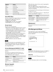
...] [Confirm] Setting Sets the year. Sets the hour (in of the [System Configuration] menu. Note The screen saver function is automatically reduced to [On] during manual adjustment of the color temperature, contrast, brightness, chroma, and phase, regardless of the setting of [Software Version], [Kernel Version], [FPGA Version] are displayed. Activates the license. Submenu [Software Upgrade] [Kernel Upgrade] [FPGA Upgrade] Setting Upgrades the software for the Sony service representative is displayed. [File Management] Menu The...
...] [Confirm] Setting Sets the year. Sets the hour (in of the [System Configuration] menu. Note The screen saver function is automatically reduced to [On] during manual adjustment of the color temperature, contrast, brightness, chroma, and phase, regardless of the setting of [Software Version], [Kernel Version], [FPGA Version] are displayed. Activates the license. Submenu [Software Upgrade] [Kernel Upgrade] [FPGA Upgrade] Setting Upgrades the software for the Sony service representative is displayed. [File Management] Menu The...

Operation Guide
Page 71
... check the sync part. When the button is set to off (Internal Sync), a sync signal is added on the Y signal to monitor the analog component signal and on the G signal to the external sync mode when the analog component signal or analog RGB signal is turned on the signal format. Set from 05 to assign [Flicker Free]. Sets the SDCP port number. When the displayed signal is synchronized with software version 1.3 or higher or BKM-17R to assign [Black Detail Mode]. Use the...
... check the sync part. When the button is set to off (Internal Sync), a sync signal is added on the Y signal to monitor the analog component signal and on the G signal to the external sync mode when the analog component signal or analog RGB signal is turned on the signal format. Set from 05 to assign [Flicker Free]. Sets the SDCP port number. When the displayed signal is synchronized with software version 1.3 or higher or BKM-17R to assign [Black Detail Mode]. Use the...

Operation Guide
Page 72
... screen. For information about the aperture modification frequency for each button. 72 Adjustment Using the Menus The degree of the [Auxiliary Setting] menu. It makes it easy to adjust chroma and phase, and to check VTR noise. [R Off]: R (red) signals are cut respectively. [G Off]: G (green) signals are cut respectively. [B Off]: B (blue) signals are inverted horizontally and displayed. [Black Frame Insertion] 1): The signal is displayed in black frame insertion mode...
... screen. For information about the aperture modification frequency for each button. 72 Adjustment Using the Menus The degree of the [Auxiliary Setting] menu. It makes it easy to adjust chroma and phase, and to check VTR noise. [R Off]: R (red) signals are cut respectively. [G Off]: G (green) signals are cut respectively. [B Off]: B (blue) signals are inverted horizontally and displayed. [Black Frame Insertion] 1): The signal is displayed in black frame insertion mode...

Operation Guide
Page 85
... chromaticity points. Parallel remote RJ-45 (×1) Serial remote (LAN) Ethernet (10BASE-T/100BASE-TX) RJ-45 (×1) 85 Specifications Specifications BVM-E251 Picture performance Panel OLED panel Picture size (diagonal) 623.4 mm (24 5/8 inches) Effective picture size (H × V) 543.4 × 305.6 mm (21 1/2 × 12 1/8 inches) Resolution (H × V) 1920 × 1080 pixels (Full HD) Aspect 16:9 Pixel efficiency 99.99% Panel drive RGB 10-bit Panel display frame rate 48 Hz, 50...
... chromaticity points. Parallel remote RJ-45 (×1) Serial remote (LAN) Ethernet (10BASE-T/100BASE-TX) RJ-45 (×1) 85 Specifications Specifications BVM-E251 Picture performance Panel OLED panel Picture size (diagonal) 623.4 mm (24 5/8 inches) Effective picture size (H × V) 543.4 × 305.6 mm (21 1/2 × 12 1/8 inches) Resolution (H × V) 1920 × 1080 pixels (Full HD) Aspect 16:9 Pixel efficiency 99.99% Panel drive RGB 10-bit Panel display frame rate 48 Hz, 50...

Operation Guide
Page 86
... oz) Accessories supplied AC power cord (1) AC plug holder (1) HDMI cable holder (1) Before Using This Unit (1) CD-ROM (1) European Representative (1) Optional accessories BKM-17R/BKM-16R Monitor Control Unit BKM-37H/BKM-38H Controller Attachment Stand SMF-17R20 Monitor Interface Cable BVM-E171 Picture performance Panel OLED panel Picture size (diagonal) 419.7 mm (16 1/2 inches) Effective picture size (H × V) 365.8× 205.7 mm (14 1/2 × 8 1/8 inches) Resolution (H × V) 1920 × 1080 pixels (Full HD...
... oz) Accessories supplied AC power cord (1) AC plug holder (1) HDMI cable holder (1) Before Using This Unit (1) CD-ROM (1) European Representative (1) Optional accessories BKM-17R/BKM-16R Monitor Control Unit BKM-37H/BKM-38H Controller Attachment Stand SMF-17R20 Monitor Interface Cable BVM-E171 Picture performance Panel OLED panel Picture size (diagonal) 419.7 mm (16 1/2 inches) Effective picture size (H × V) 365.8× 205.7 mm (14 1/2 × 8 1/8 inches) Resolution (H × V) 1920 × 1080 pixels (Full HD...


