

Operation Manual
Page 2
... REMOVE COVER. REFER SERVICING TO QUALIFIED SERVICE PERSONNEL. ment. ONLY WARNING: High brightness light source. CONSUMER PRODUCT SAFETY ACT To ensure that children do not expose this equip- Be especially careful that you have checked the contents of the carton thoroughly against the list of "Supplied accessories" on the bottom of the projector and retain this operation manual carefully. DO NOT REMOVE SCREWS EXCEPT SPECIFIED USER SERVICE SCREWS...
... REMOVE COVER. REFER SERVICING TO QUALIFIED SERVICE PERSONNEL. ment. ONLY WARNING: High brightness light source. CONSUMER PRODUCT SAFETY ACT To ensure that children do not expose this equip- Be especially careful that you have checked the contents of the carton thoroughly against the list of "Supplied accessories" on the bottom of the projector and retain this operation manual carefully. DO NOT REMOVE SCREWS EXCEPT SPECIFIED USER SERVICE SCREWS...
Operation Manual
Page 3
... for a Class B digital device, pursuant to Part 15 of mercury. Ensure the cooling fan has stopped before disconnecting the power cord. DURING NORMAL OPERATION, NEVER TURN THE PROJECTOR OFF BY DISCONNECTING THE POWER CORD. PRODUCT DISPOSAL This projector utilizes tin-lead solder, and a pressurized lamp containing a small amount of the FCC Rules. Caution Concerning the Lamp Replacement See "Replacing the Lamp" on the remote control. If this device...
... for a Class B digital device, pursuant to Part 15 of mercury. Ensure the cooling fan has stopped before disconnecting the power cord. DURING NORMAL OPERATION, NEVER TURN THE PROJECTOR OFF BY DISCONNECTING THE POWER CORD. PRODUCT DISPOSAL This projector utilizes tin-lead solder, and a pressurized lamp containing a small amount of the FCC Rules. Caution Concerning the Lamp Replacement See "Replacing the Lamp" on the remote control. If this device...
Operation Manual
Page 4
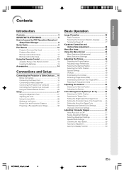
... Connecting 16 Connecting the Power Cord 16 Connecting to Video Equipment 17 Connecting the Projector to Access the PDF Operation Manuals of SharpVision Manager 8 Quick Guide 9 Part Names 10 Projector (Front and Top View 10 Projector (Rear View 11 Remote Control (Front View 12 Remote Control (Top View 12 Using the Remote Control 13 Available Range of All Color Settings 56 Adjusting Computer Images 57 When Auto Sync is OFF 57 Saving Adjustment Settings 57 Selecting Adjustment Settings 58 Special Mode Settings 58 Checking the Input Signal 59 Auto Sync Adjustment 59 Auto Sync...
... Connecting 16 Connecting the Power Cord 16 Connecting to Video Equipment 17 Connecting the Projector to Access the PDF Operation Manuals of SharpVision Manager 8 Quick Guide 9 Part Names 10 Projector (Front and Top View 10 Projector (Rear View 11 Remote Control (Front View 12 Remote Control (Top View 12 Using the Remote Control 13 Available Range of All Color Settings 56 Adjusting Computer Images 57 When Auto Sync is OFF 57 Saving Adjustment Settings 57 Selecting Adjustment Settings 58 Special Mode Settings 58 Checking the Input Signal 59 Auto Sync Adjustment 59 Auto Sync...

Operation Manual
Page 5
... Automatic Power Off Function 72 Selecting the Transmission Speed (RS-232C 72 Reversing/Inverting Projected Images 73 Displaying the Adjustment Settings 74 Appendix Maintenance 76 Cleaning the Ventilative Holes 77 Maintenance Indicators 78 Regarding the Lamp 80 Lamp 80 Caution Concerning the Lamp 80 Replacing the Lamp 80 Removing and Installing the Lamp Unit 81 Resetting the Lamp Timer 82 Connecting Pin Assignments 83 (RS-232C) Specifications and Command Settings 84 Wired Remote Control Terminal Specifications 87...
... Automatic Power Off Function 72 Selecting the Transmission Speed (RS-232C 72 Reversing/Inverting Projected Images 73 Displaying the Adjustment Settings 74 Appendix Maintenance 76 Cleaning the Ventilative Holes 77 Maintenance Indicators 78 Regarding the Lamp 80 Lamp 80 Caution Concerning the Lamp 80 Replacing the Lamp 80 Removing and Installing the Lamp Unit 81 Resetting the Lamp Timer 82 Connecting Pin Assignments 83 (RS-232C) Specifications and Command Settings 84 Wired Remote Control Terminal Specifications 87...

Operation Manual
Page 8
...;C). Other connected equipment I The operating temperature for details. Internal cleaning should be cleaned more often. I When connecting a computer or other cables connected to hard impact and/or vibration, as the cooling fan also stops. Remove the projector power cord from -4°F to 140°F (-20°C to "Maintenance In- I For minimal servicing and to the projector, make your eyes occasionally. See "Replacing the Lamp" on the projector will...
...;C). Other connected equipment I The operating temperature for details. Internal cleaning should be cleaned more often. I When connecting a computer or other cables connected to hard impact and/or vibration, as the cooling fan also stops. Remove the projector power cord from -4°F to 140°F (-20°C to "Maintenance In- I For minimal servicing and to the projector, make your eyes occasionally. See "Replacing the Lamp" on the projector will...

Operation Manual
Page 10
... 13) Power cord Video equipment Composite video cable (commercially available) 1. Place the projector facing a wall or a screen. 2. Adjust the image size, image position and the focus. (Page 28, 29) Adjust the focus by moving the zoom knob. Turn on the remote control. (Page 34) ON button INPUT 4 button The power indicator illuminates blue. Press on the remote control to video equipment. (Page 17) 6. ON put terminal 3. Remove the lens cap from setup to projection. Adjust the zooming by rotating the focus ring. Lens cap Adjust the height...
... 13) Power cord Video equipment Composite video cable (commercially available) 1. Place the projector facing a wall or a screen. 2. Adjust the image size, image position and the focus. (Page 28, 29) Adjust the focus by moving the zoom knob. Turn on the remote control. (Page 34) ON button INPUT 4 button The power indicator illuminates blue. Press on the remote control to video equipment. (Page 17) 6. ON put terminal 3. Remove the lens cap from setup to projection. Adjust the zooming by rotating the focus ring. Lens cap Adjust the height...

Operation Manual
Page 11
... INPUT button For switching input mode 1, 2, 3, 4 or 5. 34 ON button For turning the power on , this operation manual, the illustration and the screen display are simplified for explanation, and may differ slightly from the lens. 78 Lamp indicator Illuminates blue, indicating normal function. When the power is in standby. Intake vent 27 Adjustment foot 13 Remote control sensor -10 XV_Z12000_E_US_p05_14.p65 10 In this indicator will illuminate red. Lens shift dial 29 Zoom knob 28 Focus ring...
... INPUT button For switching input mode 1, 2, 3, 4 or 5. 34 ON button For turning the power on , this operation manual, the illustration and the screen display are simplified for explanation, and may differ slightly from the lens. 78 Lamp indicator Illuminates blue, indicating normal function. When the power is in standby. Intake vent 27 Adjustment foot 13 Remote control sensor -10 XV_Z12000_E_US_p05_14.p65 10 In this indicator will illuminate red. Lens shift dial 29 Zoom knob 28 Focus ring...

Operation Manual
Page 12
... 17 INPUT 3 terminal Terminal for instructions on a desktop, high mounted or ceiling mounted, attach the terminal cover (supplied) to secure the projector. Introduction Projector (Rear View) INPUT 1 terminals 18 Terminals for DVI digital, computer RGB and component signals. INPUT 2 terminals 18 Terminals for use it to hide the connecting cables. Refer to the information that came with the system for connecting video equipment with your fingers. Using the Kensington Lock This projector has...
... 17 INPUT 3 terminal Terminal for instructions on a desktop, high mounted or ceiling mounted, attach the terminal cover (supplied) to secure the projector. Introduction Projector (Rear View) INPUT 1 terminals 18 Terminals for DVI digital, computer RGB and component signals. INPUT 2 terminals 18 Terminals for use it to hide the connecting cables. Refer to the information that came with the system for connecting video equipment with your fingers. Using the Kensington Lock This projector has...

Operation Manual
Page 13
... or returning to the respective input signal type. Backlight button For lighting all buttons on the menu. Remote Control (Top View) Remote control signal transmitters 13 -12 XV_Z12000_E_US_p05_14.p65 12 34 ON button For turning the power on. 42 MENU button For displaying adjustment and setting screens. 43 Adjustment buttons For selecting menu items. 35 INPUT buttons For switching to a computer. AUTO SYNC button 59 For automatically adjusting images when connected to the respective input modes. 62 RESIZE button For switching the screen size (SIDE BAR, SMART STRETCH, etc...
... or returning to the respective input signal type. Backlight button For lighting all buttons on the menu. Remote Control (Top View) Remote control signal transmitters 13 -12 XV_Z12000_E_US_p05_14.p65 12 34 ON button For turning the power on. 42 MENU button For displaying adjustment and setting screens. 43 Adjustment buttons For selecting menu items. 35 INPUT buttons For switching to a computer. AUTO SYNC button 59 For automatically adjusting images when connected to the respective input modes. 62 RESIZE button For switching the screen size (SIDE BAR, SMART STRETCH, etc...

Operation Manual
Page 32
... is an error of ±3% in the formula above . • Values with a minus (-) sign indicate the distance of the lens center below the bottom of the screen. -31 XV_Z12000_E_US_p27_32.p65 31 03.9.24, 1:58 PM Screen Size and Projection Distance x yz Connections and Setup When using a wide screen (16:9) In case of displaying the 16:9 picture on the whole of the 16:9 screen. 16 9 : Picture area Screen size (16...
... is an error of ±3% in the formula above . • Values with a minus (-) sign indicate the distance of the lens center below the bottom of the screen. -31 XV_Z12000_E_US_p27_32.p65 31 03.9.24, 1:58 PM Screen Size and Projection Distance x yz Connections and Setup When using a wide screen (16:9) In case of displaying the 16:9 picture on the whole of the 16:9 screen. 16 9 : Picture area Screen size (16...

Operation Manual
Page 35
... red, and the projector enters standby mode. 2 Press on the remote control or on , and then transmit the commands. Image Projection Basic Procedure Connect the required external equipment to start operation. After the lamp indicator illuminates, the projector is English. ", ',\, | buttons ENTER button Note • The lamp indicator illuminates, indicating the status of the lamp. Blue: The lamp is warming up. Blue blinking: The lamp is ready. STANDBY button ENTER button Power indicator Lamp indicator MENU button INPUT button STANDBY button ON button ON button MENU button...
... red, and the projector enters standby mode. 2 Press on the remote control or on , and then transmit the commands. Image Projection Basic Procedure Connect the required external equipment to start operation. After the lamp indicator illuminates, the projector is English. ", ',\, | buttons ENTER button Note • The lamp indicator illuminates, indicating the status of the lamp. Blue: The lamp is warming up. Blue blinking: The lamp is ready. STANDBY button ENTER button Power indicator Lamp indicator MENU button INPUT button STANDBY button ON button ON button MENU button...

Operation Manual
Page 79
... repair. • Clogged air intake • Clean the ventilative holes according to turn off and then the projector will turn on the projector a fourth time without replacing the lamp, the projector will be displayed on / Standby Red blinks The lamp does not illuminate. I If you try to the procedure on . ceeds 1,900 cumulative hours of the picture. At this time, the LAMP REPLACEMENT indicator will enter the standby mode. cation, " " will blink in yellow. sures. If the temperature keeps...
... repair. • Clogged air intake • Clean the ventilative holes according to turn off and then the projector will turn on the projector a fourth time without replacing the lamp, the projector will be displayed on / Standby Red blinks The lamp does not illuminate. I If you try to the procedure on . ceeds 1,900 cumulative hours of the picture. At this time, the LAMP REPLACEMENT indicator will enter the standby mode. cation, " " will blink in yellow. sures. If the temperature keeps...

Operation Manual
Page 81
...-SHARP (1-877-388-7427). I This projector utilizes a pressurized mercury lamp. Because the gas in the bulb cracking. Then carefully change the lamp by a 90-day parts and labor limited warranty. CUSTOMERS: The lamp included with "Lamp Timer" in this projector is backed by following the instructions described in the "Options" menu on -screen display icon are illuminated or flash, it is recommended you may have the lamp replaced...
...-SHARP (1-877-388-7427). I This projector utilizes a pressurized mercury lamp. Because the gas in the bulb cracking. Then carefully change the lamp by a 90-day parts and labor limited warranty. CUSTOMERS: The lamp included with "Lamp Timer" in this projector is backed by following the instructions described in the "Options" menu on -screen display icon are illuminated or flash, it is recommended you may have the lamp replaced...
Operation Manual
Page 83
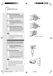
...; If the lamp unit and lamp cover are not correctly installed, the power will not turn on the projector. • "LAMP 0000H" is displayed, indicating that the lamp timer is connected to become damaged or explode. -82 XV_Z12000_E_US_p75_88.p65 82 2 1 User service screws 03.9.26, 6:39 PM If you reset the lamp timer and continue to use the same lamp, this may cause the lamp to the projector. Hold the lamp unit by the...
...; If the lamp unit and lamp cover are not correctly installed, the power will not turn on the projector. • "LAMP 0000H" is displayed, indicating that the lamp timer is connected to become damaged or explode. -82 XV_Z12000_E_US_p75_88.p65 82 2 1 User service screws 03.9.26, 6:39 PM If you reset the lamp timer and continue to use the same lamp, this may cause the lamp to the projector. Hold the lamp unit by the...

Operation Manual
Page 85
... table. If the projector receives a command other than one code is being sent, send each adjustment menu and checking the status with the "POWER ON" command, wait for at least 30 seconds after the response code for connection.) Communication conditions Set the serial port settings of the computer to match that of INPUT 1 image adjustment is turned on during standby with the on-screen display. (RS-232C) Specifications and Command Settings PC control A computer can be...
... table. If the projector receives a command other than one code is being sent, send each adjustment menu and checking the status with the "POWER ON" command, wait for at least 30 seconds after the response code for connection.) Communication conditions Set the serial port settings of the computer to match that of INPUT 1 image adjustment is turned on during standby with the on-screen display. (RS-232C) Specifications and Command Settings PC control A computer can be...

Operation Manual
Page 90
... temperature changes. noise appears. Power indicator and lamp indicator do not come on while projecting. • Adjust the focus. • The projection distance exceeds the focus range. (Computer Input only) • Perform "Fine Sync" Adjustments ("Clock" Adjustment) • Perform "Fine Sync" Adjustments ("Phase" Adjustment) • Noise will not affect operation or performance. • See "Maintenance Indicators". • "LED" is set to minimum position. • Picture adjustments are incorrectly set. (Video Input only) • Video input system is incorrectly set. (INPUT...
... temperature changes. noise appears. Power indicator and lamp indicator do not come on while projecting. • Adjust the focus. • The projection distance exceeds the focus range. (Computer Input only) • Perform "Fine Sync" Adjustments ("Clock" Adjustment) • Perform "Fine Sync" Adjustments ("Phase" Adjustment) • Noise will not affect operation or performance. • See "Maintenance Indicators". • "LED" is set to minimum position. • Picture adjustments are incorrectly set. (Video Input only) • Video input system is incorrectly set. (INPUT...

Operation Manual
Page 91
... . Troubleshooting Problem Picture is green on INPUT 1 or 2 RGB. Check • Change the input signal type setting. • The lamp indicator is http://www.sharpusa.com/ . -90 XV_Z12000_E_US_p89_96.p65 90 03.9.24, 2:10 PM A response code cannot be controlled using RS-232C commands from a computer during standby, it takes a maximum of transmitting RS-232C commands from a computer during setup or operation of the computer to receive the response code. NENT. Replace the lamp...
... . Troubleshooting Problem Picture is green on INPUT 1 or 2 RGB. Check • Change the input signal type setting. • The lamp indicator is http://www.sharpusa.com/ . -90 XV_Z12000_E_US_p89_96.p65 90 03.9.24, 2:10 PM A response code cannot be controlled using RS-232C commands from a computer during standby, it takes a maximum of transmitting RS-232C commands from a computer during setup or operation of the computer to receive the response code. NENT. Replace the lamp...
Operation Manual
Page 92
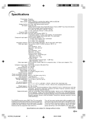
... manual Replacement parts Lamp unit (Lamp/cage module) (BQC-XVZ100005), Remote control (RRMCGA216WJSA), AA size batteries , Power cord (CACCDA024DE01), Terminal cover (CCOVA1985CE03), Lens cap (PCAPH1056CESA), SharpVision Manager Software CD-ROM (UDSKAA040WJZZ), Projector operation manual (TINS-A970WJZZ), SharpVision Manager operation manual (TINS-B097WJZZ) This SHARP projector uses a DMD Chip. This unit has some inactive pixels within acceptable tolerances which may result in inactive dots on sync Input level (Synchronizing input) 0.286 Vp-p Input Impedance 75 Ω Video input signal...
... manual Replacement parts Lamp unit (Lamp/cage module) (BQC-XVZ100005), Remote control (RRMCGA216WJSA), AA size batteries , Power cord (CACCDA024DE01), Terminal cover (CCOVA1985CE03), Lens cap (PCAPH1056CESA), SharpVision Manager Software CD-ROM (UDSKAA040WJZZ), Projector operation manual (TINS-A970WJZZ), SharpVision Manager operation manual (TINS-B097WJZZ) This SHARP projector uses a DMD Chip. This unit has some inactive pixels within acceptable tolerances which may result in inactive dots on sync Input level (Synchronizing input) 0.286 Vp-p Input Impedance 75 Ω Video input signal...

Operation Manual
Page 95
... button 46 Power cord 16 Power indicator 34 PRJ mode 73 IP Mode 49 Remote control 12 Remote control sensor 13 Replacing the lamp 80 RESIZE button 62 Reversing/Inverting Projected Images 73 RGB/COMP. Index 2D Progressive 49 3D Progressive 49 AC socket 16 Adjusting Computer Images 57 Adjusting the Lens 28 Adjusting the Picture 46 Adjustment buttons 43 Adjustment feet 27 Aspect ratio 63 Auto Power Off 72 Auto Sync Adjustment 59 AUTO SYNC button 59 Auto Sync Disp 60 Background 70 Batteries 13 Ceiling-mount setup...
... button 46 Power cord 16 Power indicator 34 PRJ mode 73 IP Mode 49 Remote control 12 Remote control sensor 13 Replacing the lamp 80 RESIZE button 62 Reversing/Inverting Projected Images 73 RGB/COMP. Index 2D Progressive 49 3D Progressive 49 AC socket 16 Adjusting Computer Images 57 Adjusting the Lens 28 Adjusting the Picture 46 Adjustment buttons 43 Adjustment feet 27 Aspect ratio 63 Auto Power Off 72 Auto Sync Adjustment 59 AUTO SYNC button 59 Auto Sync Disp 60 Background 70 Batteries 13 Ceiling-mount setup...
Operation Manual
Page 96
...FITNESS FOR USE ARE LIMITED TO THE PERIOD(S) FROM THE DATE OF PURCHASE SET FORTH BELOW. From a Sharp Authorized Servicer located in custom enclosures, projectors connected to third party control and ...Projector Lamp, parts and labor for a lamp replacement are the responsibility of which has been damaged or defaced, which has been subjected to the purchaser with a standard (8' step) ladder or ceilings exceeding 12' in -home service for this Product. Labor & materials required to remove and reinstall a projector in complex systems including, but not limited to, projectors installed...
...FITNESS FOR USE ARE LIMITED TO THE PERIOD(S) FROM THE DATE OF PURCHASE SET FORTH BELOW. From a Sharp Authorized Servicer located in custom enclosures, projectors connected to third party control and ...Projector Lamp, parts and labor for a lamp replacement are the responsibility of which has been damaged or defaced, which has been subjected to the purchaser with a standard (8' step) ladder or ceilings exceeding 12' in -home service for this Product. Labor & materials required to remove and reinstall a projector in complex systems including, but not limited to, projectors installed...


