Service Manual
Page 1
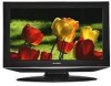
Be sure to replace these parts with " " are subject to change without notice. SHARP CORPORATION This document has been published to be used for maintaining the safety of the set . CONTENTS Page • CAUTION ...A1-1 • IMPORTANT SAFEGUARDS... EXPLODED VIEWS J2-1 • REPLACEMENT PARTS LIST K1-1~K3-8 Parts marked with specified ones for maintaining the safety and performance of the set . SERVICE MANUAL S68ONLC32DV24 COMBINATION LIQUID CRYSTAL TELEVISION AND DVD/CD PLAYER MODEL LC-32DV24U In the interests of user-safety (Required by safety regulations in some countries...
Be sure to replace these parts with " " are subject to change without notice. SHARP CORPORATION This document has been published to be used for maintaining the safety of the set . CONTENTS Page • CAUTION ...A1-1 • IMPORTANT SAFEGUARDS... EXPLODED VIEWS J2-1 • REPLACEMENT PARTS LIST K1-1~K3-8 Parts marked with specified ones for maintaining the safety and performance of the set . SERVICE MANUAL S68ONLC32DV24 COMBINATION LIQUID CRYSTAL TELEVISION AND DVD/CD PLAYER MODEL LC-32DV24U In the interests of user-safety (Required by safety regulations in some countries...
Service Manual
Page 2
... BEAM, DO NOT TRY TO OPEN THE ENCLOSURE. DO NOT STARE INTO BEAM. CERTIFICATION: COMPLIES WITH FDA RADIATION PERFORMANCE STANDARDS, 21 CFR SUBCHAPTER J. CAUTION THIS LCD COLOR TELEVISION EMPLOYS A LASER SYSTEM. VISIBLE LASER RADIATION MAY BE PRESENT WHEN THE ENCLOSURE IS OPENED. Please perform the following measure against static electricity, such... OF PROCEDURES OTHER THAN THOSE SPECIFIED HEREIN MAY RESULT IN HAZARDOUS LASER RADIATION EXPOSURE. TO ENSURE PROPER USE OF THIS PRODUCT, PLEASE READ THIS SERVICE MANUAL CAREFULLY AND RETAIN FOR FUTURE REFERENCE.
... BEAM, DO NOT TRY TO OPEN THE ENCLOSURE. DO NOT STARE INTO BEAM. CERTIFICATION: COMPLIES WITH FDA RADIATION PERFORMANCE STANDARDS, 21 CFR SUBCHAPTER J. CAUTION THIS LCD COLOR TELEVISION EMPLOYS A LASER SYSTEM. VISIBLE LASER RADIATION MAY BE PRESENT WHEN THE ENCLOSURE IS OPENED. Please perform the following measure against static electricity, such... OF PROCEDURES OTHER THAN THOSE SPECIFIED HEREIN MAY RESULT IN HAZARDOUS LASER RADIATION EXPOSURE. TO ENSURE PROPER USE OF THIS PRODUCT, PLEASE READ THIS SERVICE MANUAL CAREFULLY AND RETAIN FOR FUTURE REFERENCE.
Service Manual
Page 4
... substitutions may cause injury. 23) When you turn off the power and unplug all of the disc slot as the original part. Read the owner's manual of antenna discharge unit, connection to grounding electrodes, and requirements for the grounding electrode. Otherwise, sudden high volume sound may cause an electric shock and...
... substitutions may cause injury. 23) When you turn off the power and unplug all of the disc slot as the original part. Read the owner's manual of antenna discharge unit, connection to grounding electrodes, and requirements for the grounding electrode. Otherwise, sudden high volume sound may cause an electric shock and...
Service Manual
Page 6
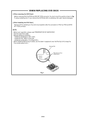
Fig. 1 A1-5 NOTE • Before your operation, please read "PREPARATION OF SERVICING". • Use the Lead Free solder. • Manual soldering conditions • Soldering temperature: 320 ± 20oC • Soldering time: Within 3 seconds • Soldering combination: Sn-3.0Ag-0.5Cu • When Soldering/Removing of Pick ...
Fig. 1 A1-5 NOTE • Before your operation, please read "PREPARATION OF SERVICING". • Use the Lead Free solder. • Manual soldering conditions • Soldering temperature: 320 ± 20oC • Soldering time: Within 3 seconds • Soldering combination: Sn-3.0Ag-0.5Cu • When Soldering/Removing of Pick ...
Service Manual
Page 14
GENERAL SPECIFICATIONS G-12 Accessories G-13 Interface Owner's Manual Language w/Guarantee Card Remote Control Unit Rod Antenna Poles Terminal Loop Antenna Terminal U/V Mixer DC Car Cord (Center+) Guarantee Card Warning Sheet Circuit Diagram Antenna ...
GENERAL SPECIFICATIONS G-12 Accessories G-13 Interface Owner's Manual Language w/Guarantee Card Remote Control Unit Rod Antenna Poles Terminal Loop Antenna Terminal U/V Mixer DC Car Cord (Center+) Guarantee Card Warning Sheet Circuit Diagram Antenna ...
Service Manual
Page 16
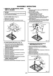
... from it. 5. Remove the Operation PCB and Operation 2 PCB in the direction of arrow. (1) (1) (2) (1) (2) (2) (2) (1) (2) (2) (1) (1) (2) (1) (1) (1) Back Cabinet (1) (1) (1) (1) NOTE 1. Before your operation, please read "PREPARATION OF SERVICING". 2. Manual soldering conditions • Soldering temperature: 320 ± 20oC • Soldering time: Within 3 seconds • Soldering combination: Sn-3.0Ag-0.5Cu 4. If you remove the DVD Deck...
... from it. 5. Remove the Operation PCB and Operation 2 PCB in the direction of arrow. (1) (1) (2) (1) (2) (2) (2) (1) (2) (2) (1) (1) (2) (1) (1) (1) Back Cabinet (1) (1) (1) (1) NOTE 1. Before your operation, please read "PREPARATION OF SERVICING". 2. Manual soldering conditions • Soldering temperature: 320 ± 20oC • Soldering time: Within 3 seconds • Soldering combination: Sn-3.0Ag-0.5Cu 4. If you remove the DVD Deck...
Service Manual
Page 19
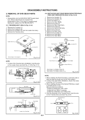
... DECK PARTS NOTE 1. Remove the 3 screws (1). 2. Remove the Switch PCB Ass'y. 9. Remove the Gear Feed. 11. Remove the 2 screws (5). 12. Remove the Feed Motor. 13. Manual soldering conditions • Soldering temperature: 320 ± 20oC • Soldering time: Within 3 seconds • Soldering combination: Sn-3.0Ag-0.5Cu 4. If the repair is needed if...
... DECK PARTS NOTE 1. Remove the 3 screws (1). 2. Remove the Switch PCB Ass'y. 9. Remove the Gear Feed. 11. Remove the 2 screws (5). 12. Remove the Feed Motor. 13. Manual soldering conditions • Soldering temperature: 320 ± 20oC • Soldering time: Within 3 seconds • Soldering combination: Sn-3.0Ag-0.5Cu 4. If the repair is needed if...


