Service Manual
Page 1
... REPARATION iii PRECAUTIONS FOR USING LEAD-FREE SOLDER iv PRECAUTIONS IN SERVICING THE HDCPKEY ROM v CHAPTER 6. SPECIFICATIONS [1] SPECIFICATIONS 1-1 CHAPTER 2. DIMENSIONS [1] DIMENSIONS 3-1 CHAPTER 4. S08S2LCC4655U LCD COLOR TELEVISION MODEL LC-C4655U In the interests of user-safety (Required by safety regulations in some parts. TopPage LC-C4655U SERVICE MANUAL No. ADJUSTMENT [1] ADJUSTMENT PROCEDURE 5-1 Parts marked with specified ones for maintaining the safety of the set. This document has been published to change without notice. For the...
... REPARATION iii PRECAUTIONS FOR USING LEAD-FREE SOLDER iv PRECAUTIONS IN SERVICING THE HDCPKEY ROM v CHAPTER 6. SPECIFICATIONS [1] SPECIFICATIONS 1-1 CHAPTER 2. DIMENSIONS [1] DIMENSIONS 3-1 CHAPTER 4. S08S2LCC4655U LCD COLOR TELEVISION MODEL LC-C4655U In the interests of user-safety (Required by safety regulations in some parts. TopPage LC-C4655U SERVICE MANUAL No. ADJUSTMENT [1] ADJUSTMENT PROCEDURE 5-1 Parts marked with specified ones for maintaining the safety of the set. This document has been published to change without notice. For the...
Service Manual
Page 2
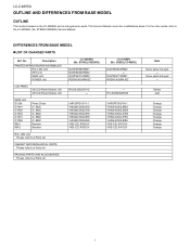
...BASE MODEL „LIST OF CHANGED PARTS Ref. Some parts changed - S08S2LCC4655U) DUNTKE264FM02 ← DUNTKE716FM01 RDENCA295WJQZ - R1LK460D3LW60Z VHPGPFSV51M-1 VHIS24CS02JBES VHIS24CS02JDES VHIS24CS02JCES VHIS24CS02JFES VHIS24CS02JEES VRS-CZ1JF470JY VRS-CZ1JF470JY Note Some parts changed - S78N2LC42D65U) DUNTKE868FM01 DUNTKE266FM02 DUNTKE716FM02 RDENCA298WJQZ LCD PANEL 42"LCD Panel Module Unit 46"LCD Panel Module Unit R1LK420D3LF21Z - LC-C4655U LOCU-C4T6L55IUNE AND DIFFERENCES FROM BASE MSOerDvEicLe Manual OUTLINE This model is based on the LC-42D65U and is changed...
...BASE MODEL „LIST OF CHANGED PARTS Ref. Some parts changed - S08S2LCC4655U) DUNTKE264FM02 ← DUNTKE716FM01 RDENCA295WJQZ - R1LK460D3LW60Z VHPGPFSV51M-1 VHIS24CS02JBES VHIS24CS02JDES VHIS24CS02JCES VHIS24CS02JFES VHIS24CS02JEES VRS-CZ1JF470JY VRS-CZ1JF470JY Note Some parts changed - S78N2LC42D65U) DUNTKE868FM01 DUNTKE266FM02 DUNTKE716FM02 RDENCA298WJQZ LCD PANEL 42"LCD Panel Module Unit 46"LCD Panel Module Unit R1LK420D3LF21Z - LC-C4655U LOCU-C4T6L55IUNE AND DIFFERENCES FROM BASE MSOerDvEicLe Manual OUTLINE This model is based on the LC-42D65U and is changed...
Service Manual
Page 3
... parts in LCD color television have the same safety characteristics as the factory recommended replacement parts shown in the following safety checks: 3. electrical components having a return to the chassis (antenna, metal cabinet, screw heads, knobs and control shafts, escutcheon, etc.) and measure the AC voltage drop across the resistor. • Connect the resistor connection to the user, perform the following manner. • Plug the AC cord directly...
... parts in LCD color television have the same safety characteristics as the factory recommended replacement parts shown in the following safety checks: 3. electrical components having a return to the chassis (antenna, metal cabinet, screw heads, knobs and control shafts, escutcheon, etc.) and measure the AC voltage drop across the resistor. • Connect the resistor connection to the user, perform the following manner. • Plug the AC cord directly...
Service Manual
Page 5
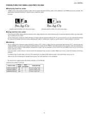
... LF shows the type of tin, silver and copper. Indicates lead-free solder of this model employs lead-free solder. PRECAUTIONS FOR USING LEAD-FREE SOLDER LC-C4655U „Employing lead-free solder • "PWBs" of tin, silver and copper. „Using lead-free wire solder • When fixing the PWB soldered with the PWB for servicing PARTS CODE ZHNDAi123250E ZHNDAi126500E ZHNDAi12801KE PRICE RANK BL BK...
... LF shows the type of tin, silver and copper. Indicates lead-free solder of this model employs lead-free solder. PRECAUTIONS FOR USING LEAD-FREE SOLDER LC-C4655U „Employing lead-free solder • "PWBs" of tin, silver and copper. „Using lead-free wire solder • When fixing the PWB soldered with the PWB for servicing PARTS CODE ZHNDAi123250E ZHNDAi126500E ZHNDAi12801KE PRICE RANK BL BK...
Service Manual
Page 7
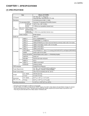
... jack) INPUT 7 HDMI in with HDCP Rear INPUT 8 HDMI in with HDCP Terminals ANT/CABLE AUDIO 75 Unbalance, F Type 1 for Analog (VHF/UHF/CATV) and Digital (AIR/CABLE) Audio in (Ø 3.5 mm jack) DIGITAL AUDIO OUTPUT Optical Digital audio output 1 (PCM/Dolby Digital) OUTPUT Audio out RS-232C 9-pin D-sub male connector INPUT 3 AV in Side INPUT 5 HDMI in individual units. 1 - 1 There may be some deviations from these values in with HDCP SERVICE Software update OSD language English/French/Spanish Power Requirement...
... jack) INPUT 7 HDMI in with HDCP Rear INPUT 8 HDMI in with HDCP Terminals ANT/CABLE AUDIO 75 Unbalance, F Type 1 for Analog (VHF/UHF/CATV) and Digital (AIR/CABLE) Audio in (Ø 3.5 mm jack) DIGITAL AUDIO OUTPUT Optical Digital audio output 1 (PCM/Dolby Digital) OUTPUT Audio out RS-232C 9-pin D-sub male connector INPUT 3 AV in Side INPUT 5 HDMI in individual units. 1 - 1 There may be some deviations from these values in with HDCP SERVICE Software update OSD language English/French/Spanish Power Requirement...
Service Manual
Page 8
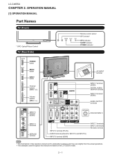
LC-C4655U LCC-HC4A655PUTER 2. The examples used throughout this operation manual are based on the LC-C5255U model. 2 - 1 OPERATION MANUAL [1] OPERATION MANUAL Part Names TV (Front) * OPC: Optical Picture Control TV (Rear/Side) Service Manual Remote control sensor OPC sensor* OPC indicator SLEEP indicator POWER indicator POWER button MENU button INPUT button Channel buttons (CH / ) Volume buttons (VOL / ) AC INPUT terminal INPUT 7 terminal (HDMI) DIGITAL AUDIO OUTPUT terminal INPUT 8 terminal (HDMI) AUDIO OUTPUT terminals INPUT 5 terminal (HDMI) Antenna/Cable in INPUT 3 terminals ...
LC-C4655U LCC-HC4A655PUTER 2. The examples used throughout this operation manual are based on the LC-C5255U model. 2 - 1 OPERATION MANUAL [1] OPERATION MANUAL Part Names TV (Front) * OPC: Optical Picture Control TV (Rear/Side) Service Manual Remote control sensor OPC sensor* OPC indicator SLEEP indicator POWER indicator POWER button MENU button INPUT button Channel buttons (CH / ) Volume buttons (VOL / ) AC INPUT terminal INPUT 7 terminal (HDMI) DIGITAL AUDIO OUTPUT terminal INPUT 8 terminal (HDMI) AUDIO OUTPUT terminals INPUT 5 terminal (HDMI) Antenna/Cable in INPUT 3 terminals ...
Service Manual
Page 9
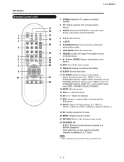
... Remote Control Unit 1 2 3 4 5 6 7 8 9 10 LC-C4655U 1 POWER: Switch the TV power on the screen. 20 10 EXIT: Turn off the menu screen. 11 DISPLAY: Display the channel information. 12 SLEEP: Set the sleep timer. 13 AV MODE: Select an audio or video setting. 21 (When the input source is INPUT 4, 5, 6 or 7: STANDARD, MOVIE, GAME, PC, xvYCC (INPUT 4/5/6 only) USER, DYNAMIC (Fixed), DYNAMIC) 14 MUTE: Mute the sound. 15 VOL / : Set the volume. 16 CH / : Select the channel. 17 ENT: Jumps to a channel after selecting with the 0-9 buttons...
... Remote Control Unit 1 2 3 4 5 6 7 8 9 10 LC-C4655U 1 POWER: Switch the TV power on the screen. 20 10 EXIT: Turn off the menu screen. 11 DISPLAY: Display the channel information. 12 SLEEP: Set the sleep timer. 13 AV MODE: Select an audio or video setting. 21 (When the input source is INPUT 4, 5, 6 or 7: STANDARD, MOVIE, GAME, PC, xvYCC (INPUT 4/5/6 only) USER, DYNAMIC (Fixed), DYNAMIC) 14 MUTE: Mute the sound. 15 VOL / : Set the volume. 16 CH / : Select the channel. 17 ENT: Jumps to a channel after selecting with the 0-9 buttons...
Service Manual
Page 10
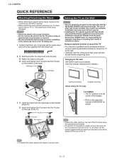
... on . To use the screws supplied with the AN-52AG4 (SHARP) wall mount bracket. Customers should only be mounted on the rear of the TV, and then use this TV mounted on a wall, remove the covers at the center of the base. Insert and tighten the 4 screws into the 8 holes on the rear of the TV. Hex key 2 Screws 2 Soft cushion 1 1 0/5/10/15/20° LC-C4655U The "b" position...
... on . To use the screws supplied with the AN-52AG4 (SHARP) wall mount bracket. Customers should only be mounted on the rear of the TV, and then use this TV mounted on a wall, remove the covers at the center of the base. Insert and tighten the 4 screws into the 8 holes on the rear of the TV. Hex key 2 Screws 2 Soft cushion 1 1 0/5/10/15/20° LC-C4655U The "b" position...
Service Manual
Page 11
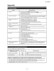
... power of an error message displayed on a screen Failed to 60°C) 2 - 4 Is the sleep timer set? Have you pressed MUTE on ? Troubleshooting-Digital Broadcasting The error message about reception of broadcast The example of the TV or unplugging the AC cord and replugging it under strong or fluorescent lighting? Check that is used in the program guide. No picture No sound The TV sometimes makes a cracking sound. Remove...
... power of an error message displayed on a screen Failed to 60°C) 2 - 4 Is the sleep timer set? Have you pressed MUTE on ? Troubleshooting-Digital Broadcasting The error message about reception of broadcast The example of the TV or unplugging the AC cord and replugging it under strong or fluorescent lighting? Check that is used in the program guide. No picture No sound The TV sometimes makes a cracking sound. Remove...
Service Manual
Page 12
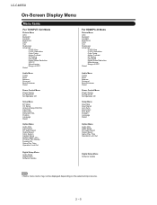
... PC Audio Select Output Select Color System Caption Setup Digital Caption Info. . LC-C4655U On-Screen Display Menu Menu Items For TV/INPUT 1/2/3 Mode Picture Menu OPC Backlight Contrast Brightness Color Tint Sharpness Advanced C.M.S.-Hue C.M.S.-Saturation Color Temp. Active Contrast I /P Setting Film Mode Digital Noise Reduction 3D-Y/C Monochrome Range of OPC Reset Audio Menu Treble Bass Balance Surround Bass Enhancer Reset Power Control Menu Power Saving No Signal Off No Operation Off Setup Menu Input Skip Input Signal Auto Sync. Program Title Display Favorite CH Game Play Time Operation...
... PC Audio Select Output Select Color System Caption Setup Digital Caption Info. . LC-C4655U On-Screen Display Menu Menu Items For TV/INPUT 1/2/3 Mode Picture Menu OPC Backlight Contrast Brightness Color Tint Sharpness Advanced C.M.S.-Hue C.M.S.-Saturation Color Temp. Active Contrast I /P Setting Film Mode Digital Noise Reduction 3D-Y/C Monochrome Range of OPC Reset Audio Menu Treble Bass Balance Surround Bass Enhancer Reset Power Control Menu Power Saving No Signal Off No Operation Off Setup Menu Input Skip Input Signal Auto Sync. Program Title Display Favorite CH Game Play Time Operation...
Service Manual
Page 14
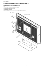
REMOVING OF MAJOR PARSTeSrvice Manual [1] REMOVING OF MAJOR PARTS 1. Remove the 1 lock screw. 4. Rear Cabinet 4 Front Cabinet 4 2 3 1 Stand 4 - 1 Remove the 4 lock screws and detach the Stand. 2. Remove the 4 VESA Hole Covers. 3. Remove the 4 lock screws, 9 lock screws and detach the Rear Cabinet. LC-C4655U LCC-HC4A655PUTER 4.
REMOVING OF MAJOR PARSTeSrvice Manual [1] REMOVING OF MAJOR PARTS 1. Remove the 1 lock screw. 4. Rear Cabinet 4 Front Cabinet 4 2 3 1 Stand 4 - 1 Remove the 4 lock screws and detach the Stand. 2. Remove the 4 VESA Hole Covers. 3. Remove the 4 lock screws, 9 lock screws and detach the Rear Cabinet. LC-C4655U LCC-HC4A655PUTER 4.
Service Manual
Page 15
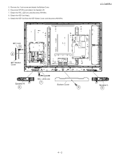
Detach the KEY Unit from the KEY Button Cover, and disconnect KM-Wire. Remove the 1 lock screw and detach the Bottom Cover. 6. 5. Detach the R/C, LED Unit, and disconnect RA-Wire. 8. Detach the KEY Unit Ass'y. 9. Disconnect SP-Wire and detach the Speaker-LR. 7. LC-C4655U KEY Unit 9 KM 8 KEY Button Cover 7 RA SP 6 RA R/C, LED Unit Speaker-R SP 7 6 Bottom Cover 5 SP Speaker-L 6 4 - 2
Detach the KEY Unit from the KEY Button Cover, and disconnect KM-Wire. Remove the 1 lock screw and detach the Bottom Cover. 6. 5. Detach the R/C, LED Unit, and disconnect RA-Wire. 8. Detach the KEY Unit Ass'y. 9. Disconnect SP-Wire and detach the Speaker-LR. 7. LC-C4655U KEY Unit 9 KM 8 KEY Button Cover 7 RA SP 6 RA R/C, LED Unit Speaker-R SP 7 6 Bottom Cover 5 SP Speaker-L 6 4 - 2
Service Manual
Page 20
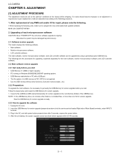
... with updated software. Main software version upgrade 2.2.1 Get ready before you start . After the unit startup, the system upgrade screen as above) into the service socket located Right side of a USB memory is FAT. (FAT32 is not applied) • Use the USB memory without other folders or unrelated files, or more than one file for the main software, monitor microprocessor software, and LCD controller software. 2.2. Unplug the AC cord. 2. ADJUSTMENT Service Manual [1] ADJUSTMENT...
... with updated software. Main software version upgrade 2.2.1 Get ready before you start . After the unit startup, the system upgrade screen as above) into the service socket located Right side of a USB memory is FAT. (FAT32 is not applied) • Use the USB memory without other folders or unrelated files, or more than one file for the main software, monitor microprocessor software, and LCD controller software. 2.2. Unplug the AC cord. 2. ADJUSTMENT Service Manual [1] ADJUSTMENT...

Service Manual
Page 22
..., unpress the power button. SDB655 6. Also, the upgrade failure screen will be shown during a minor upgrade. UPGRADE SUCCESS SDB655 8. LC-C4655U 2.3. Plug in the same manner as above) into the service socket located Right side of the monitor microprocessor software starts. If the process repeatedly fails, hardware may be shown if upgrade screen was shown at 5. CAUTION: • The moment this operation is upgraded, also perform...
..., unpress the power button. SDB655 6. Also, the upgrade failure screen will be shown during a minor upgrade. UPGRADE SUCCESS SDB655 8. LC-C4655U 2.3. Plug in the same manner as above) into the service socket located Right side of the monitor microprocessor software starts. If the process repeatedly fails, hardware may be shown if upgrade screen was shown at 5. CAUTION: • The moment this operation is upgraded, also perform...

Service Manual
Page 24
... the remote controller, once unplug the AC cord and plug it again. LC-C4655U 3. In this mode, unrecoverable system damage may result. 4. The letter "" appears on the power. Entering and exiting the adjustment process mode 1) Before entering the adjustment process mode, the AV position RESET in the video adjustment menu. 2) While holding down the "VOL (-)" and "CH ( )" keys at a time, plug in the AC cord of display in the adjustment process mode.
... the remote controller, once unplug the AC cord and plug it again. LC-C4655U 3. In this mode, unrecoverable system damage may result. 4. The letter "" appears on the power. Entering and exiting the adjustment process mode 1) Before entering the adjustment process mode, the AV position RESET in the video adjustment menu. 2) While holding down the "VOL (-)" and "CH ( )" keys at a time, plug in the AC cord of display in the adjustment process mode.

Service Manual
Page 25
List of termination due to lamp error Initialization to factory settings Public mode Accumulated main operation time Reset Accumulated monitor operation time Reset Reset LAMP ERROR X-coordinate setting for VIC READ Y-coordinate setting for VIC READ Collected color data setting for VIC READ Signal type setting for VIC READ Picture level acquisition function CVBS and TUNER signal level adjustment CVBS signal level adjustment TUNER signal level adjustment Tuning test and VCHIP test (69ch) Tuning test and VCHIP test (7ch) Tuning test...
List of termination due to lamp error Initialization to factory settings Public mode Accumulated main operation time Reset Accumulated monitor operation time Reset Reset LAMP ERROR X-coordinate setting for VIC READ Y-coordinate setting for VIC READ Collected color data setting for VIC READ Signal type setting for VIC READ Picture level acquisition function CVBS and TUNER signal level adjustment CVBS signal level adjustment TUNER signal level adjustment Tuning test and VCHIP test (69ch) Tuning test and VCHIP test (7ch) Tuning test...

Service Manual
Page 31
...) : 0.7Vp-p ± 0.02Vp-p : 0.7Vp-p ± 0.02Vp-p (Pedestal to TUNER-A. [Video input signal] [US-10CH] 2 Auto adjustment performance Page 3/38 7.4. Special features * STANDBY CAUSE (Page 1/38) Display of a cause (code) of the last standby The cause of the last standby is listed in finding a problem when you repair the troubled set. * EEP SAVE (Page 38/38) Storage of EEP adjustment value * EEP RECOVER (Page 38/38...
...) : 0.7Vp-p ± 0.02Vp-p : 0.7Vp-p ± 0.02Vp-p (Pedestal to TUNER-A. [Video input signal] [US-10CH] 2 Auto adjustment performance Page 3/38 7.4. Special features * STANDBY CAUSE (Page 1/38) Display of a cause (code) of the last standby The cause of the last standby is listed in finding a problem when you repair the troubled set. * EEP SAVE (Page 38/38) Storage of EEP adjustment value * EEP RECOVER (Page 38/38...
Service Manual
Page 33
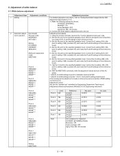
.... Correct the G setting (184 x 6th- White balance adjustment LC-C4655U Adjustment item Adjustment conditions Adjustment procedure 1 Setting For detailed adjustment procedure, refer to the specified gradation level. With the strongest color being fixed, KKT10037 turn off ), and make the R and B settings to their reference levels. 7) Set the 1st point to "Kameyama Model Integral Monitor WB Adjustment Specifications V1.6". 1) Make the following settings for inspection AV MODE: [DYNAMIC] (Reset) Monochro: ON Active...
.... Correct the G setting (184 x 6th- White balance adjustment LC-C4655U Adjustment item Adjustment conditions Adjustment procedure 1 Setting For detailed adjustment procedure, refer to the specified gradation level. With the strongest color being fixed, KKT10037 turn off ), and make the R and B settings to their reference levels. 7) Set the 1st point to "Kameyama Model Integral Monitor WB Adjustment Specifications V1.6". 1) Make the following settings for inspection AV MODE: [DYNAMIC] (Reset) Monochro: ON Active...

Service Manual
Page 34
... this adjustment. 1) User setting 2) Channel data (e.g. Get ready the PC with the remote controller, once unplug the power cable and plug it again. After the settings are initialized in the adjustment process mode are not initialized.) Adjustment item Adjustment conditions Adjustment procedure 1 Initialization It turns off with the RS-232C cable connected. 3. supply. ried out. (If an error occurs, "ERROR" is displayed on the Internet will do.) 4. Send the process mode switching command to switch from...
... this adjustment. 1) User setting 2) Channel data (e.g. Get ready the PC with the remote controller, once unplug the power cable and plug it again. After the settings are initialized in the adjustment process mode are not initialized.) Adjustment item Adjustment conditions Adjustment procedure 1 Initialization It turns off with the RS-232C cable connected. 3. supply. ried out. (If an error occurs, "ERROR" is displayed on the Internet will do.) 4. Send the process mode switching command to switch from...
Service Manual
Page 44
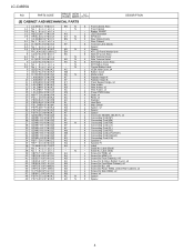
... XEBS740P08000 48 PSPAZC225WJKZ 49 PSPAZC221WJKZ BN N - N - Badge, SHARP J LED Decoration X SP Sheet X Rear Cabinet Ass'y - Label (Side) J Screw (for PWB), x3 J Screw (for HDMI), x3 J Screw (for Front Cabinet), x10 J Screw (for S-Video, Bottom Cover), x2 J Screw (for Front/Rear Cabinet), x9 J Screw (for BL), x36 J Screw (for Power PWB), x6/(for Rear Cabinet), x4 J Screw (for Side HDMI), x2 J Screw, x6 X Spacer X Spacer 4 LC-C4655U NO. N AD N AK N - Serial No.
... XEBS740P08000 48 PSPAZC225WJKZ 49 PSPAZC221WJKZ BN N - N - Badge, SHARP J LED Decoration X SP Sheet X Rear Cabinet Ass'y - Label (Side) J Screw (for PWB), x3 J Screw (for HDMI), x3 J Screw (for Front Cabinet), x10 J Screw (for S-Video, Bottom Cover), x2 J Screw (for Front/Rear Cabinet), x9 J Screw (for BL), x36 J Screw (for Power PWB), x6/(for Rear Cabinet), x4 J Screw (for Side HDMI), x2 J Screw, x6 X Spacer X Spacer 4 LC-C4655U NO. N AD N AK N - Serial No.


