

Service Manual
Page 1
DVD VIDEO PLAYER MODEL DV-SL90UM CONTENTS Page SPECIFICATIONS ...1-1-1 LASER BEAM SAFETY PRECAUTIONS 1-2-1 IMPORTANT SAFEGUARDS AND PRECAUTIONS 1-3-1 STANDARD NOTES FOR SERVICING 1-4-1 OPERATING CONTROLS AND FUNCTIONS 1-5-1 CABINET DISASSEMBLY INSTRUCTIONS 1-6-1 ...-1 This document has been published to be used . SERVICE MANUAL DV-SL90UM SERVICE MANUAL S64U2DV-SL90U DVD VIDEO PLAYER 4 MODEL DV-SL90UM In the interests of user-safety (Required by safety regulations in some countries) the set should be used for SHARP CORPORATION after sales service only. 1 The contents are subject to ...
DVD VIDEO PLAYER MODEL DV-SL90UM CONTENTS Page SPECIFICATIONS ...1-1-1 LASER BEAM SAFETY PRECAUTIONS 1-2-1 IMPORTANT SAFEGUARDS AND PRECAUTIONS 1-3-1 STANDARD NOTES FOR SERVICING 1-4-1 OPERATING CONTROLS AND FUNCTIONS 1-5-1 CABINET DISASSEMBLY INSTRUCTIONS 1-6-1 ...-1 This document has been published to be used . SERVICE MANUAL DV-SL90UM SERVICE MANUAL S64U2DV-SL90U DVD VIDEO PLAYER 4 MODEL DV-SL90UM In the interests of user-safety (Required by safety regulations in some countries) the set should be used for SHARP CORPORATION after sales service only. 1 The contents are subject to ...

Service Manual
Page 2
... ~ 22 kHz dB 1k Hz 0 dB % 1k Hz 0 dB % 14 W (Standby: 2.0 W) 2.9 lbs (1.3kg) 435 mm X 51 mm X 211 mm NOTES: 1. Load imp. : 100 k ohm 4. Response DVD CD 3-4. All Items are measured without pre-emphasis unless otherwise specified. 2. Room ambient : 5 °C ~ 40 °C NOMINAL 1.0 500 2.0 120 ±0.5 ±0.5 0.0025 0.003 LIMIT ±...
... ~ 22 kHz dB 1k Hz 0 dB % 1k Hz 0 dB % 14 W (Standby: 2.0 W) 2.9 lbs (1.3kg) 435 mm X 51 mm X 211 mm NOTES: 1. Load imp. : 100 k ohm 4. Response DVD CD 3-4. All Items are measured without pre-emphasis unless otherwise specified. 2. Room ambient : 5 °C ~ 40 °C NOMINAL 1.0 500 2.0 120 ±0.5 ±0.5 0.0025 0.003 LIMIT ±...

Service Manual
Page 3
... to keep your skin. Do not look directly at least 30cm away from the location shown in hazardous radiation exposure. LASER BEAM SAFETY PRECAUTIONS This DVD player uses a pickup that emits a laser beam. Caution: Use of controls and adjustments, or doing procedures other than those specified herein, may result in the...
... to keep your skin. Do not look directly at least 30cm away from the location shown in hazardous radiation exposure. LASER BEAM SAFETY PRECAUTIONS This DVD player uses a pickup that emits a laser beam. Caution: Use of controls and adjustments, or doing procedures other than those specified herein, may result in the...
Service Manual
Page 9
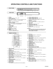
... see the sequence being played back from the beginning of a selected section. 8. TOP MENU Button Displays the title menu. 16. MENU Button Displays the DVD menus and MP3 file lists. 20. STOP Button Stops operation of a TV 15. SKIP Button Plays back from the tray. 26. AUDIO OUT (Left... Button Press to change setup items. 13. MODE Button Activates program playback or random playback mode.(CD/MP3) Activates the Virtual Surround or Rapid Play.(DVD) 14. COMPONENT VIDEO OUT connect to a TV with Component video in jacks 16. SETUP Button Press to enter the setup mode or to a ...
... see the sequence being played back from the beginning of a selected section. 8. TOP MENU Button Displays the title menu. 16. MENU Button Displays the DVD menus and MP3 file lists. 20. STOP Button Stops operation of a TV 15. SKIP Button Plays back from the tray. 26. AUDIO OUT (Left... Button Press to change setup items. 13. MODE Button Activates program playback or random playback mode.(CD/MP3) Activates the Virtual Surround or Rapid Play.(DVD) 14. COMPONENT VIDEO OUT connect to a TV with Component video in jacks 16. SETUP Button Press to enter the setup mode or to a ...

Service Manual
Page 10
.... Open the battery compartment cover. Insert two AA batteries, with each one oriented correctly. Power off 3. P.SCAN DVD VCD Displays a type of the title or track. Tray closed Loading the Disc Lights up when the playback control ...mix alkaline and manganese batteries. Lights up when the repeat function is activated. DVD: DVD CD: Audio CD, MP3, JPEG, Kodak Picture CD VCD: Video CD Lights up when playing back in ...slow mode. (DVD) Lights up when the inserted disc is switched. The number of a new title, chapter, or...
.... Open the battery compartment cover. Insert two AA batteries, with each one oriented correctly. Power off 3. P.SCAN DVD VCD Displays a type of the title or track. Tray closed Loading the Disc Lights up when the playback control ...mix alkaline and manganese batteries. Lights up when the repeat function is activated. DVD: DVD CD: Audio CD, MP3, JPEG, Kodak Picture CD VCD: Video CD Lights up when playing back in ...slow mode. (DVD) Lights up when the inserted disc is switched. The number of a new title, chapter, or...
Service Manual
Page 11
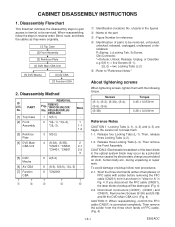
... they were originally. [1] Top Case [2] Front Assembly [3] Reinforce Plate [4] DVD Main CBA Unit [5] DVD Mecha [6] AV CBA 1 : Identification (location) No. PART No. [1] Top Case [2] Front Assembly [3] Reinforce Plate [4] DVD Main CBA Unit [5] DVD Mecha [6] AV CBA [7] Function CBA ↑ ↑ 1 2 REMOVAL... to be serviced. To avoid damage of pickup will be destroyed. (Fig. 4) 2-2. Remove two Screws (S-3A) and (S-3B) and lift the DVD Main CBA Unit. (Fig. 4) CAUTION 3: When reassembling, confirm the FFC cable (CN201) is connected completely. P=Spring, L=Locking Tab, S=Screw,...
... they were originally. [1] Top Case [2] Front Assembly [3] Reinforce Plate [4] DVD Main CBA Unit [5] DVD Mecha [6] AV CBA 1 : Identification (location) No. PART No. [1] Top Case [2] Front Assembly [3] Reinforce Plate [4] DVD Main CBA Unit [5] DVD Mecha [6] AV CBA [7] Function CBA ↑ ↑ 1 2 REMOVAL... to be serviced. To avoid damage of pickup will be destroyed. (Fig. 4) 2-2. Remove two Screws (S-3A) and (S-3B) and lift the DVD Main CBA Unit. (Fig. 4) CAUTION 3: When reassembling, confirm the FFC cable (CN201) is connected completely. P=Spring, L=Locking Tab, S=Screw,...

Service Manual
Page 12
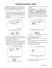
[1] Top Case (S-1) (L-1) (L-3) (L-1) Fig. 1 (L-2) [2] Front Assembly Fig. 2 (S-2) [3] Reinforce Plate CN201 CN301 (S-3B) (S-3A) CN601 CN401 A [4] DVD Main CBA Unit Solder Short lands OR Short lands Short the three short lands by soldering. (Either of two places.) Solder FPC Cable View for A Fig. 4 (S-4) [5] DVD Mecha (S-4) Fig. 3 (S-4) 1-6-2 Fig. 5 E592ADC
[1] Top Case (S-1) (L-1) (L-3) (L-1) Fig. 1 (L-2) [2] Front Assembly Fig. 2 (S-2) [3] Reinforce Plate CN201 CN301 (S-3B) (S-3A) CN601 CN401 A [4] DVD Main CBA Unit Solder Short lands OR Short lands Short the three short lands by soldering. (Either of two places.) Solder FPC Cable View for A Fig. 4 (S-4) [5] DVD Mecha (S-4) Fig. 3 (S-4) 1-6-2 Fig. 5 E592ADC
Service Manual
Page 15
...F/W Version Up Mode Model No : ******* VERSION : *.** VERSION : E5****_****.ab5 Reading...(*2) Fig. h appears on the models. To put the DVD player into the memory 2 Erasing... c is finished, the tray opens automatically. Erasing previous version data 3 Programming... e appears on the screen ...are available. 6. a will open . 3. Fig. "*******" differ depending on the screen. 1-7-1 E5945TEST Load the disc for F/W Version Up. The DVD player enters the F/W version up mode, press [9], [8], [7], [6], and [SEARCH MODE] buttons on by pressing the [POWER] button and the ...
...F/W Version Up Mode Model No : ******* VERSION : *.** VERSION : E5****_****.ab5 Reading...(*2) Fig. h appears on the models. To put the DVD player into the memory 2 Erasing... c is finished, the tray opens automatically. Erasing previous version data 3 Programming... e appears on the screen ...are available. 6. a will open . 3. Fig. "*******" differ depending on the screen. 1-7-1 E5945TEST Load the disc for F/W Version Up. The DVD player enters the F/W version up mode, press [9], [8], [7], [6], and [SEARCH MODE] buttons on by pressing the [POWER] button and the ...
Service Manual
Page 19
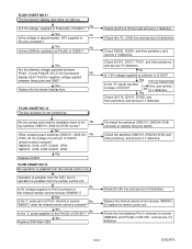
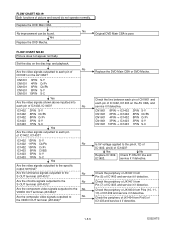
...- Yes When pressing each pin of IC2001 (shown below) increase? FLOW CHART NO.13 No operation is activated? Operation is possible from the DVD, but no operation is not functioning. Check R2002, IC2001 and their periphery, and service it if defective. Check the switches (SW2101, SW2104-2108...service it if detective. FLOW CHART NO.11 The fluorescent display tube does not light up. Yes Replace the fluorescent display tube. Yes Replace DVD Main CBA. Check EV+5V line and service it if defective. Or replace the remote control unit. Check D1016, D1017, T1001, and...
...- Yes When pressing each pin of IC2001 (shown below) increase? FLOW CHART NO.13 No operation is activated? Operation is possible from the DVD, but no operation is not functioning. Check R2002, IC2001 and their periphery, and service it if defective. Check the switches (SW2101, SW2104-2108...service it if detective. FLOW CHART NO.11 The fluorescent display tube does not light up. Yes Replace the fluorescent display tube. Yes Replace DVD Main CBA. Check EV+5V line and service it if defective. Or replace the remote control unit. Check D1016, D1017, T1001, and...

Service Manual
Page 20
... Disc] indicated. (When the focus servo is poor. No Original DVD Main CBA is poor. Replace the DVD Main CBA. Replace the DVD Main CBA. Yes Replace the DVD Mecha. No Original DVD Main CBA is poor. 1-8-4 E592ATS No improvement can be found. No Original DVD Main CBA is poor. No improvement can be done using... Refer to Pin(4) of IC2001? FLOW CHART NO.15 The disc tray cannot be found. No improvement can be opened and closed . Yes Replace the DVD Mecha. FLOW CHART NO.18 [No Disc] indicated. (When the laser beam does not light up.) Replace the...
... Disc] indicated. (When the focus servo is poor. No Original DVD Main CBA is poor. Replace the DVD Main CBA. Replace the DVD Main CBA. Yes Replace the DVD Mecha. No Original DVD Main CBA is poor. 1-8-4 E592ATS No improvement can be found. No Original DVD Main CBA is poor. No improvement can be done using... Refer to Pin(4) of IC2001? FLOW CHART NO.15 The disc tray cannot be found. No improvement can be opened and closed . Yes Replace the DVD Mecha. FLOW CHART NO.18 [No Disc] indicated. (When the laser beam does not light up.) Replace the...
Service Manual
Page 21
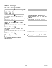
... signals outputted to the No VIDEO OUT terminal (JK1404)? Check the periphery of JK1401 from Pin (5) of IC1403 and service it if detective. Replace the DVD Main CBA. No Original DVD Main CBA is poor. Are the component video signals outputted to the No S-OUT terminal (JK1401)? Replace the... DVD Main CBA or DVD Mecha. Check the periphery of JK1401 from Pin (7) of IC1403 and service it if detective. FLOW CHART NO.19 Both functions of IC1402, IC1403 on ...
... signals outputted to the No VIDEO OUT terminal (JK1404)? Check the periphery of JK1401 from Pin (5) of IC1403 and service it if detective. Replace the DVD Main CBA. No Original DVD Main CBA is poor. Are the component video signals outputted to the No S-OUT terminal (JK1401)? Replace the... DVD Main CBA or DVD Mecha. Check the periphery of JK1401 from Pin (7) of IC1403 and service it if detective. FLOW CHART NO.19 Both functions of IC1402, IC1403 on ...
Service Manual
Page 22
...IC1201 2PIN AUDIO-L IC1201 6PIN AUDIO-R Yes Is the "H" level mute signal outputted to each pin of CN1601 on AV CBA ? Replace the DVD Main CBA or DVD Mecha. No Are the analog audio signals outputted to CN1601 on AV CBA? CN1601 14PIN → IC1201 2PIN AUDIO-L CN1601 16PIN →... IC1201 6PIN AUDIO-R Replace the DVD Main CBA or DVD Mecha. Check the periphery between each pin of CN1601 and each line between Pins(1,7) of IC1201 on the disc tray, and playback. Set...
...IC1201 2PIN AUDIO-L IC1201 6PIN AUDIO-R Yes Is the "H" level mute signal outputted to each pin of CN1601 on AV CBA ? Replace the DVD Main CBA or DVD Mecha. No Are the analog audio signals outputted to CN1601 on AV CBA? CN1601 14PIN → IC1201 2PIN AUDIO-L CN1601 16PIN →... IC1201 6PIN AUDIO-R Replace the DVD Main CBA or DVD Mecha. Check the periphery between each pin of CN1601 and each line between Pins(1,7) of IC1201 on the disc tray, and playback. Set...

Service Manual
Page 23
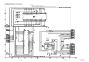
... 22 143 SP-ROT 81 SL-AMP RM2001 REMOTE SENSOR K2 4 K1 3 SEGMENT CN2001 5 KEY-1 3 KEY-2 4 KEY-3 6 KEY-4 1 K2 2 K1 CN2101 5 3 4 6 1 2 KEY MATRIX 1-9-1 DRIVE CBA DVD MAIN CBA UNIT 66 TRAY-IN AV CBA FUNCTION CBA E592ABLS BLOCK DIAGRAMS System Control / Servo Block Diagram TO VIDEO/ AUDIO BLOCK DIAGRAM PCM-SCLK...
... 22 143 SP-ROT 81 SL-AMP RM2001 REMOTE SENSOR K2 4 K1 3 SEGMENT CN2001 5 KEY-1 3 KEY-2 4 KEY-3 6 KEY-4 1 K2 2 K1 CN2101 5 3 4 6 1 2 KEY MATRIX 1-9-1 DRIVE CBA DVD MAIN CBA UNIT 66 TRAY-IN AV CBA FUNCTION CBA E592ABLS BLOCK DIAGRAMS System Control / Servo Block Diagram TO VIDEO/ AUDIO BLOCK DIAGRAM PCM-SCLK...
Service Manual
Page 24
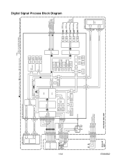
... DECODER I ) 1-9-2 TS FS 4 IC201 (SW) CN201 FS(+) 2 FS(-) 3 TS(+) 1 TS(-) 4 FS(+) FS(-) TS(+) TS(-) TO SYSTEM CONTROL/SERVO BLOCK DIAGRAM PICK-UP UNIT DVD MAIN CBA UNIT 192~212 DEBUG 23~51 INST RAM DATA RAM FADR (0-19) FDQ (0-15) * IC103 (FLASH ROM) 1 ~~ 9 16 25 48 FLASH ROM ~~ 29... 36 38 45 E592ABLD Be sure to replace with the DVD Main CBA unit when servicing IC103. Digital Signal Process Block Diagram DATA(VIDEO/AUDIO) SIGNAL VIDEO SIGNAL DATA(AUDIO) SIGNAL *Note: IC103 is not supplied...
... DECODER I ) 1-9-2 TS FS 4 IC201 (SW) CN201 FS(+) 2 FS(-) 3 TS(+) 1 TS(-) 4 FS(+) FS(-) TS(+) TS(-) TO SYSTEM CONTROL/SERVO BLOCK DIAGRAM PICK-UP UNIT DVD MAIN CBA UNIT 192~212 DEBUG 23~51 INST RAM DATA RAM FADR (0-19) FDQ (0-15) * IC103 (FLASH ROM) 1 ~~ 9 16 25 48 FLASH ROM ~~ 29... 36 38 45 E592ABLD Be sure to replace with the DVD Main CBA unit when servicing IC103. Digital Signal Process Block Diagram DATA(VIDEO/AUDIO) SIGNAL VIDEO SIGNAL DATA(AUDIO) SIGNAL *Note: IC103 is not supplied...
Service Manual
Page 32
Be sure to replace with the DVD Main CBA unit when servicing IC103. 1-10-9 1-10-10 E592ASCD3 DVD Main 3/3 Schematic Diagram * Note: IC103 is not supplied separately.
Be sure to replace with the DVD Main CBA unit when servicing IC103. 1-10-9 1-10-10 E592ASCD3 DVD Main 3/3 Schematic Diagram * Note: IC103 is not supplied separately.

Service Manual
Page 35
AV 3/3 & Function Schematic Diagram 7G 6G 5G 4G 3G 2G 1G VCR REPEAT TITLE GROUP AB ALL f i i REC SACD CHP TRK PSCAN a c b DVD A d PM f g e HD VCD FL2001 MATRIX CHART 7G 6G 5G 4G a a a a b REPEAT b b b cA c c c dB d d d e ALL e e e f f f f f g g g g h GROUP i i TITLE VCR 3G 2G 1G a a SACD b b PSCAN c c DVD d d A e eP f fM g g HD CHP TRK V REC CD 1-10-15 1-10-16 E592ASCAV3
AV 3/3 & Function Schematic Diagram 7G 6G 5G 4G 3G 2G 1G VCR REPEAT TITLE GROUP AB ALL f i i REC SACD CHP TRK PSCAN a c b DVD A d PM f g e HD VCD FL2001 MATRIX CHART 7G 6G 5G 4G a a a a b REPEAT b b b cA c c c dB d d d e ALL e e e f f f f f g g g g h GROUP i i TITLE VCR 3G 2G 1G a a SACD b b PSCAN c c DVD d d A e eP f fM g g HD CHP TRK V REC CD 1-10-15 1-10-16 E592ASCAV3

Service Manual
Page 41
WAVEFORMS WF1 Pin 8 of CN1601 WF5 Pin 16 of CN1601 VIDEO-Y 0.2V 20µs WF2 Pin 10 of CN1601 AUDIO-R 1V 0.5ms WF6 Pin 19 of CN1601 VIDEO-C 0.2V 20µs WF3 C1402 PLUS LEAD VIDEO-CVBS 0.5V 20µs WF4 Pin 14 of CN1601 SPDIF 1V 0.1µs NOTE: Input CD: 1kHz PLAY (WF4~WF6) DVD: POWER ON (STOP) MODE (WF1~WF3) AUDIO-L 1V 0.5ms 1-11 -1 E5945WF
WAVEFORMS WF1 Pin 8 of CN1601 WF5 Pin 16 of CN1601 VIDEO-Y 0.2V 20µs WF2 Pin 10 of CN1601 AUDIO-R 1V 0.5ms WF6 Pin 19 of CN1601 VIDEO-C 0.2V 20µs WF3 C1402 PLUS LEAD VIDEO-CVBS 0.5V 20µs WF4 Pin 14 of CN1601 SPDIF 1V 0.1µs NOTE: Input CD: 1kHz PLAY (WF4~WF6) DVD: POWER ON (STOP) MODE (WF1~WF3) AUDIO-L 1V 0.5ms 1-11 -1 E5945WF

Service Manual
Page 42
... D 18 A 17 C 16 B 15 E 14 VREF 13 F 12 GND 11 CD-LD 10 GND(LD) 9 DVD-LD 8 PD-MONI 7 GND(DVD-PD) 6 GND(CD-PD) 5 TS(-) 4 FS(-) 3 FS(+) 2 TS(+) 1 DVD MAIN CBA UNIT (9HSN79S8HZP) 1 EV+1.2V 1 2 EV+1.2V 2 3 EV+3.3V 3 4 EV+3.3V 4 5 EV+3.3V 5 6 P-ON+3.3V 6 7 P-ON+5V 7 8 EV+11V 8 9 EV+11V 9 10... 20 FP-STB 20 21 FP-DOUT 21 22 REMOTE 22 CN401 CN301 SL(+) 8 SL(-) 7 GND 6 TRAY-IN 5 SP(-) 4 SP(+) 3 1-12-1 SLED MOTOR M SPINDLE MOTOR M DVD MECHA TRAY-IN DRIVE CBA FS TS 7 9 11 2 3 6 5 4 DETECTOR PICK UP UNIT E592AWI OUT OUT OUT VIDEO-Y VIDEO-Cb/Pb VIDEO-Cr/Pr VIDEO OUT...
... D 18 A 17 C 16 B 15 E 14 VREF 13 F 12 GND 11 CD-LD 10 GND(LD) 9 DVD-LD 8 PD-MONI 7 GND(DVD-PD) 6 GND(CD-PD) 5 TS(-) 4 FS(-) 3 FS(+) 2 TS(+) 1 DVD MAIN CBA UNIT (9HSN79S8HZP) 1 EV+1.2V 1 2 EV+1.2V 2 3 EV+3.3V 3 4 EV+3.3V 4 5 EV+3.3V 5 6 P-ON+3.3V 6 7 P-ON+5V 7 8 EV+11V 8 9 EV+11V 9 10... 20 FP-STB 20 21 FP-DOUT 21 22 REMOTE 22 CN401 CN301 SL(+) 8 SL(-) 7 GND 6 TRAY-IN 5 SP(-) 4 SP(+) 3 1-12-1 SLED MOTOR M SPINDLE MOTOR M DVD MECHA TRAY-IN DRIVE CBA FS TS 7 9 11 2 3 6 5 4 DETECTOR PICK UP UNIT E592AWI OUT OUT OUT VIDEO-Y VIDEO-Cb/Pb VIDEO-Cr/Pr VIDEO OUT...

Service Manual
Page 46
Numbers are not in sequence. 2L081 2B5 2L081 2L011 2L011 2L011 A2 2L021 2L021 2L021 Function CBA A16 2L021 1B1 2L105 DVD Main CBA Unit 2L105 2L031 JK1401 JK1404 JK1202 F1001 AV CBA 2B1 A21 IC1204 2B11 2L042 AC1001 2L041 A13 A1X A13 A15 1-16-1 E592AEX Some Ref. Cabinet EXPLODED VIEWS See Electrical Parts List for parts with this mark.
Numbers are not in sequence. 2L081 2B5 2L081 2L011 2L011 2L011 A2 2L021 2L021 2L021 Function CBA A16 2L021 1B1 2L105 DVD Main CBA Unit 2L105 2L031 JK1401 JK1404 JK1202 F1001 AV CBA 2B1 A21 IC1204 2B11 2L042 AC1001 2L041 A13 A1X A13 A15 1-16-1 E592AEX Some Ref. Cabinet EXPLODED VIEWS See Electrical Parts List for parts with this mark.
Service Manual
Page 48
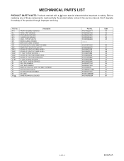
...FRONT ASSEMBLY E592AZD PANEL,TRAY E5920UD FOOT(REAR) E5710UD CHASSIS(V0) E5946AD CASE, TOP E5 PLASTIC RATING LABEL E592AZD BAR CODE LABEL E592AZD DVD MECHA(FG LESS) 0838 VCZL0500 REINFORCE PLATE E5 PLASTIC SCREW, P-TIGHT 3X10 BIND HEAD+ SCREW, P-TIGHT 3X11 BIND HEAD+ P-TIGHT SCREW..., P-TIGHT M3X8 WASHER+ P-TIGHT SCREW 3X8 BIND + GIFT BOX, CARTON E592AZD SIDE PAD E5900UD UNIT, BAG E5500UD REMOTE CONTROL UNIT DVD 0842 VCZF05EE DRY BATTERY R6P/2S ACCESSORY BAG E5700UD AV CORD OWNER'S MANUAL E592AZD Part No. 9HS1VM220174 9HS0VM204430 9HS0VM415007 9HS0VM204661 9HS0VM306830 9HSN79F0HVM 9HS0VM306575 ...
...FRONT ASSEMBLY E592AZD PANEL,TRAY E5920UD FOOT(REAR) E5710UD CHASSIS(V0) E5946AD CASE, TOP E5 PLASTIC RATING LABEL E592AZD BAR CODE LABEL E592AZD DVD MECHA(FG LESS) 0838 VCZL0500 REINFORCE PLATE E5 PLASTIC SCREW, P-TIGHT 3X10 BIND HEAD+ SCREW, P-TIGHT 3X11 BIND HEAD+ P-TIGHT SCREW..., P-TIGHT M3X8 WASHER+ P-TIGHT SCREW 3X8 BIND + GIFT BOX, CARTON E592AZD SIDE PAD E5900UD UNIT, BAG E5500UD REMOTE CONTROL UNIT DVD 0842 VCZF05EE DRY BATTERY R6P/2S ACCESSORY BAG E5700UD AV CORD OWNER'S MANUAL E592AZD Part No. 9HS1VM220174 9HS0VM204430 9HS0VM415007 9HS0VM204661 9HS0VM306830 9HSN79F0HVM 9HS0VM306575 ...


