

Service Manual
Page 1
DVD VIDEO PLAYER MODEL DV-SL90UM CONTENTS Page SPECIFICATIONS ...1-1-1 LASER BEAM SAFETY PRECAUTIONS 1-2-1 IMPORTANT SAFEGUARDS AND PRECAUTIONS 1-3-1 STANDARD NOTES FOR SERVICING 1-4-1 OPERATING CONTROLS AND FUNCTIONS 1-5-1 CABINET DISASSEMBLY INSTRUCTIONS 1-6-1 FIRMWARE RENEWAL MODE ...1-7-1 TROUBLESHOOTING ...1-8-1 BLOCK DIAGRAMS ...1-9-1 SCHEMATIC DIAGRAMS/ CBA'S AND TEST POINTS 1-10-1 WAVEFORMS ...1-11-1 WIRING DIAGRAM ...1-12-1 SYSTEM CONTROL TIMING CHARTS 1-13-1 IC PIN FUNCTION DESCRIPTIONS 1-14-1 LEAD IDENTIFICATIONS ...1-15-1 EXPLODED VIEWS ...1-16-1 MECHANICAL PARTS LIST ...
DVD VIDEO PLAYER MODEL DV-SL90UM CONTENTS Page SPECIFICATIONS ...1-1-1 LASER BEAM SAFETY PRECAUTIONS 1-2-1 IMPORTANT SAFEGUARDS AND PRECAUTIONS 1-3-1 STANDARD NOTES FOR SERVICING 1-4-1 OPERATING CONTROLS AND FUNCTIONS 1-5-1 CABINET DISASSEMBLY INSTRUCTIONS 1-6-1 FIRMWARE RENEWAL MODE ...1-7-1 TROUBLESHOOTING ...1-8-1 BLOCK DIAGRAMS ...1-9-1 SCHEMATIC DIAGRAMS/ CBA'S AND TEST POINTS 1-10-1 WAVEFORMS ...1-11-1 WIRING DIAGRAM ...1-12-1 SYSTEM CONTROL TIMING CHARTS 1-13-1 IC PIN FUNCTION DESCRIPTIONS 1-14-1 LEAD IDENTIFICATIONS ...1-15-1 EXPLODED VIEWS ...1-16-1 MECHANICAL PARTS LIST ...

Service Manual
Page 2
...Load imp. : 100 k ohm 4. Freq. THD +N 4 Power consumption 5 Weight 6 Dimension CONDITIONS 75 Ω UNIT Vpp mVpp 1 kHz 0 dB Vrm dB fs=48 kHz 20 ~ 22 kHz dB fs=44.1 kHz 20 ~ 22 kHz dB 1k Hz 0 dB % 1k Hz 0 dB % 14 W (Standby...: 2.0 W) 2.9 lbs (1.3kg) 435 mm X 51 mm X 211 mm NOTES: 1. Room ambient : 5 °C ~ 40 °C NOMINAL 1.0 500 2.0 120 ±0.5 ±0.5 0.0025 0.003 LIMIT ±0.1 1-1-1 E5945SP Power supply : AC 110 V - 240 V 60Hz 3. SPECIFICATIONS ITEM 1 Video Output 2 Coaxial Digital Out 3 Audio (PCM) 3-1. Response DVD CD 3-4. Output Level ...
...Load imp. : 100 k ohm 4. Freq. THD +N 4 Power consumption 5 Weight 6 Dimension CONDITIONS 75 Ω UNIT Vpp mVpp 1 kHz 0 dB Vrm dB fs=48 kHz 20 ~ 22 kHz dB fs=44.1 kHz 20 ~ 22 kHz dB 1k Hz 0 dB % 1k Hz 0 dB % 14 W (Standby...: 2.0 W) 2.9 lbs (1.3kg) 435 mm X 51 mm X 211 mm NOTES: 1. Room ambient : 5 °C ~ 40 °C NOMINAL 1.0 500 2.0 120 ±0.5 ±0.5 0.0025 0.003 LIMIT ±0.1 1-1-1 E5945SP Power supply : AC 110 V - 240 V 60Hz 3. SPECIFICATIONS ITEM 1 Video Output 2 Coaxial Digital Out 3 Audio (PCM) 3-1. Response DVD CD 3-4. Output Level ...

Service Manual
Page 3
... exposure. Drive Mecha Assembly Laser Beam Radiation Laser Pickup Turntable 1-2-1 DVD_LASER LASER BEAM SAFETY PRECAUTIONS This DVD player uses a pickup that emits a laser beam. Do not look directly at least 30cm away from the pickup lens when the diode is emitted from the pickup or allow it to keep your skin. Caution: Use of controls and adjustments, or...
... exposure. Drive Mecha Assembly Laser Beam Radiation Laser Pickup Turntable 1-2-1 DVD_LASER LASER BEAM SAFETY PRECAUTIONS This DVD player uses a pickup that emits a laser beam. Do not look directly at least 30cm away from the pickup lens when the diode is emitted from the pickup or allow it to keep your skin. Caution: Use of controls and adjustments, or...

Service Manual
Page 5
...power of time. Clean the bit after every use a dedicated soldering bit, if you may cause damage or accident due to obtain lead-free wire solder or soldening bit, contact our service station or service ranch in contact with steel wool or fine sandpaper. Becareful when replacing parts with lead-free solder. ZHNDAi123250E J ZHNDAi126500E J ZHNDAi12801KE J Description Code... you to first disconnect the AC cord. 2. Repairing with the lead-free solder, apply lead-free wire solder. FFC Cable Using lead-free wire solder When fixing the PWB soldered with conventional lead wire...
...power of time. Clean the bit after every use a dedicated soldering bit, if you may cause damage or accident due to obtain lead-free wire solder or soldening bit, contact our service station or service ranch in contact with steel wool or fine sandpaper. Becareful when replacing parts with lead-free solder. ZHNDAi123250E J ZHNDAi126500E J ZHNDAi12801KE J Description Code... you to first disconnect the AC cord. 2. Repairing with the lead-free solder, apply lead-free wire solder. FFC Cable Using lead-free wire solder When fixing the PWB soldered with conventional lead wire...
Service Manual
Page 9
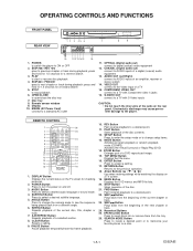
... the Video Input of a digital (coaxial) audio equipment 13. OPERATING CONTROLS AND FUNCTIONS FRONT PANEL REAR VIEW 1 2 3 45 6 7 8 9 10 1112 13 14 15 16 1. POWER to switch the player to start or resume disc playback 4. press and hold for 1.5 seconds for a forward search 5. PLAY to ON or OFF 2. press and hold for 1.5 seconds for checking purposes. 2. STOP to digital (optical) audio equipment 12. Disc tray 8. Remote sensor window 9. Display 10. OPTICAL (Digital audio out) connect to stop playback 6. AUDIO OUT...
... the Video Input of a digital (coaxial) audio equipment 13. OPERATING CONTROLS AND FUNCTIONS FRONT PANEL REAR VIEW 1 2 3 45 6 7 8 9 10 1112 13 14 15 16 1. POWER to switch the player to start or resume disc playback 4. press and hold for 1.5 seconds for a forward search 5. PLAY to ON or OFF 2. press and hold for 1.5 seconds for checking purposes. 2. STOP to digital (optical) audio equipment 12. Disc tray 8. Remote sensor window 9. Display 10. OPTICAL (Digital audio out) connect to stop playback 6. AUDIO OUT...

Service Manual
Page 10
... manganese batteries. GROUP Lights up when the inserted disc is being played back. Display Lights up when the A-B repeat function is on Lights up when the ALL repeat function is on Loading the Batteries 1. Open the battery compartment cover. Power off 3. No disc inserted or cannot read Tray open 2. DVD: DVD CD: Audio CD, MP3, JPEG, Kodak Picture CD VCD: Video CD Lights up when playing back in slow mode. (DVD) Lights up when the progressive scan system is activated. The number of...
... manganese batteries. GROUP Lights up when the inserted disc is being played back. Display Lights up when the A-B repeat function is on Lights up when the ALL repeat function is on Loading the Batteries 1. Open the battery compartment cover. Power off 3. No disc inserted or cannot read Tray open 2. DVD: DVD CD: Audio CD, MP3, JPEG, Kodak Picture CD VCD: Video CD Lights up when playing back in slow mode. (DVD) Lights up when the progressive scan system is activated. The number of...
Service Manual
Page 11
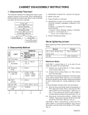
... or repair work. P=Spring, L=Locking Tab, S=Screw, CN=Connector, *=Unhook, Unlock, Release, Unplug, or Desolder e.g. 5(S-1) = five Screws (S-1), 2(L-2) = two Locking Tabs (L-2) 5 : Refer to be removed, unhooked, unlocked, released, unplugged, unclamped, or desoldered. If you disconnect the FFC cable (CN201), the laser diode of parts to "Reference Notes." [7] Function CBA 2. of parts in reverse order. PART No. [1] Top Case [2] Front Assembly [3] Reinforce Plate [4] DVD Main...
... or repair work. P=Spring, L=Locking Tab, S=Screw, CN=Connector, *=Unhook, Unlock, Release, Unplug, or Desolder e.g. 5(S-1) = five Screws (S-1), 2(L-2) = two Locking Tabs (L-2) 5 : Refer to be removed, unhooked, unlocked, released, unplugged, unclamped, or desoldered. If you disconnect the FFC cable (CN201), the laser diode of parts to "Reference Notes." [7] Function CBA 2. of parts in reverse order. PART No. [1] Top Case [2] Front Assembly [3] Reinforce Plate [4] DVD Main...
Service Manual
Page 15
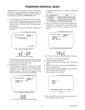
...] button on the screen, then the tray will close. 9. Fig. F/W Version Up Mode Model No : ******* VERSION : *.** Please insert a DISC for different models, "Disc Error" will open automatically. a appears on the screen. Fig. g appears on the screen and Fig. The tray will appear on the remote control unit. MODEL : ******* Version : *.** Region : * Fig. To put the DVD player into the memory 2 Erasing... Sending files into version up mode with the tray open . 3. f) "*******" differ depending on the models...
...] button on the screen, then the tray will close. 9. Fig. F/W Version Up Mode Model No : ******* VERSION : *.** Please insert a DISC for different models, "Disc Error" will open automatically. a appears on the screen. Fig. g appears on the screen and Fig. The tray will appear on the remote control unit. MODEL : ******* Version : *.** Region : * Fig. To put the DVD player into the memory 2 Erasing... Sending files into version up mode with the tray open . 3. f) "*******" differ depending on the models...
Service Manual
Page 16
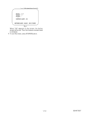
MODEL : ******* Version : *.** Region : * EEPROM CLEAR : OK EEPROM CLEAR : CLEAR EXIT: POWER Fig. h When "OK" appears on the models. Then the firmware renewal mode is complete. 11.To exit this mode, press [POWER] button. 1-7-2 E5945TEST "*******" differ depending on the screen, the factory default will be set.
MODEL : ******* Version : *.** Region : * EEPROM CLEAR : OK EEPROM CLEAR : CLEAR EXIT: POWER Fig. h When "OK" appears on the models. Then the firmware renewal mode is complete. 11.To exit this mode, press [POWER] button. 1-7-2 E5945TEST "*******" differ depending on the screen, the factory default will be set.
Service Manual
Page 19
... of each switches (SW2101, SW2104- Are the contact point and the installation state of IC2001 (shown below) increase? No Is 5V voltage supplied to base of receiver No (RM2001) when the infrared remote control is possible from the DVD, but no operation is not functioning. Check the -FL (-20V) line and service it if defective. Yes Replace the fluorescent display tube...
... of each switches (SW2101, SW2104- Are the contact point and the installation state of IC2001 (shown below) increase? No Is 5V voltage supplied to base of receiver No (RM2001) when the infrared remote control is possible from the DVD, but no operation is not functioning. Check the -FL (-20V) line and service it if defective. Yes Replace the fluorescent display tube...

Service Manual
Page 20
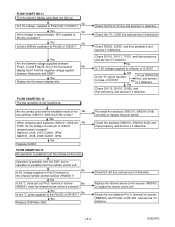
... poor. No improvement can be opened and closed . No Original DVD Main CBA is poor. 1-8-4 E592ATS No improvement can be found . Replace the DVD Main CBA. FLOW CHART NO.14 The disc tray cannot be opened and closed . (It can be done using the remote control unit.) No Is the normal control voltage inputted to "FLOW CHART NO.15" Replace the "OPEN/CLOSE" button (SW2108). Refer to "FLOW...
... poor. No improvement can be opened and closed . No Original DVD Main CBA is poor. 1-8-4 E592ATS No improvement can be found . Replace the DVD Main CBA. FLOW CHART NO.14 The disc tray cannot be opened and closed . (It can be done using the remote control unit.) No Is the normal control voltage inputted to "FLOW CHART NO.15" Replace the "OPEN/CLOSE" button (SW2108). Refer to "FLOW...
Service Manual
Page 21
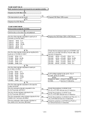
... 8PIN CN1601 10PIN S-Y Cr/Pr Cb/Pb S-Y S-C Yes Are the video signals shown above inputted into each pin of IC1403 and service it if detective. Replace the DVD Main CBA or DVD Mecha. Yes No Replace IC1402, Check P-ON+5V line and IC1403. Check the periphery of JK1401 from Pins (10, 11, 13) of picture and sound do not operate normally.
... 8PIN CN1601 10PIN S-Y Cr/Pr Cb/Pb S-Y S-C Yes Are the video signals shown above inputted into each pin of IC1403 and service it if detective. Replace the DVD Main CBA or DVD Mecha. Yes No Replace IC1402, Check P-ON+5V line and IC1403. Check the periphery of JK1401 from Pins (10, 11, 13) of picture and sound do not operate normally.
Service Manual
Page 22
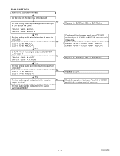
... Are the analog audio signals outputted to the specific No output terminal? IC1201 1PIN AUDIO-L No IC1201 7PIN AUDIO-R Yes Are the audio signals outputted to each pin of IC1201. Check each line between Pins(1,7) of IC1201 on AV CBA? Set the disc on AV CBA ? No Are the analog audio signals outputted to CN1601 on the disc tray, and playback. Replace the DVD Main CBA or DVD Mecha. Replace IC1201. Check...
... Are the analog audio signals outputted to the specific No output terminal? IC1201 1PIN AUDIO-L No IC1201 7PIN AUDIO-R Yes Are the audio signals outputted to each pin of IC1201. Check each line between Pins(1,7) of IC1201 on AV CBA? Set the disc on AV CBA ? No Are the analog audio signals outputted to CN1601 on the disc tray, and playback. Replace the DVD Main CBA or DVD Mecha. Replace IC1201. Check...

Service Manual
Page 23
BLOCK DIAGRAMS System Control / Servo Block Diagram TO VIDEO/ AUDIO BLOCK DIAGRAM PCM-SCLK A-MUTE ADAC-MD ADAC-MC ADAC-ML TO DIGITAL SIGNAL PROCESS BLOCK DIAGRAM FS(+) FS(-) TS(+) TS(-) +3.3V IC461 +3.3V IC462 2 RESET 1 1 RESET 3 IC301 (SERVO DRIVE) 15 FOCUS ACTUATOR 16 DRIVE +- 14 TRACKING ACTUATOR 13 DRIVE +- 12 SPINDLE MOTOR 11 DRIVE +- 17 SLED MOTOR 18 DRIVE +- VREF +- 27 26 25 24 +- 1 2 3 +- 4 5 6 23 TRAY-IN SPINDLE...
BLOCK DIAGRAMS System Control / Servo Block Diagram TO VIDEO/ AUDIO BLOCK DIAGRAM PCM-SCLK A-MUTE ADAC-MD ADAC-MC ADAC-ML TO DIGITAL SIGNAL PROCESS BLOCK DIAGRAM FS(+) FS(-) TS(+) TS(-) +3.3V IC461 +3.3V IC462 2 RESET 1 1 RESET 3 IC301 (SERVO DRIVE) 15 FOCUS ACTUATOR 16 DRIVE +- 14 TRACKING ACTUATOR 13 DRIVE +- 12 SPINDLE MOTOR 11 DRIVE +- 17 SLED MOTOR 18 DRIVE +- VREF +- 27 26 25 24 +- 1 2 3 +- 4 5 6 23 TRAY-IN SPINDLE...
Service Manual
Page 24
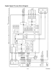
Digital Signal Process Block Diagram DATA(VIDEO/AUDIO) SIGNAL VIDEO SIGNAL DATA(AUDIO) SIGNAL *Note: IC103 is not supplied separatery. ROM DATA RAM INST. Be sure to replace with the DVD Main CBA unit when servicing IC103. ROM SERIAL GENERAL I/O INTERRUPT CONTROLLER TIMER WATCH DOG TIMER REMOTE CONTROL AUDIO I/F VIDEO I/F BCU 32BIT CPU NTSC/PAL ENCODER SPDIF 177 PCM-BCK 170 PCM-DATA 171 PCM-LRCLK 169 TO VIDEO /AUDIO BLOCK DIAGRAM Y D/A 149 VIDEO-Y C D/A 158 VIDEO-C Cr/Pr VIDEO-Cr/Pr D/A 152...
Digital Signal Process Block Diagram DATA(VIDEO/AUDIO) SIGNAL VIDEO SIGNAL DATA(AUDIO) SIGNAL *Note: IC103 is not supplied separatery. ROM DATA RAM INST. Be sure to replace with the DVD Main CBA unit when servicing IC103. ROM SERIAL GENERAL I/O INTERRUPT CONTROLLER TIMER WATCH DOG TIMER REMOTE CONTROL AUDIO I/F VIDEO I/F BCU 32BIT CPU NTSC/PAL ENCODER SPDIF 177 PCM-BCK 170 PCM-DATA 171 PCM-LRCLK 169 TO VIDEO /AUDIO BLOCK DIAGRAM Y D/A 149 VIDEO-Y C D/A 158 VIDEO-C Cr/Pr VIDEO-Cr/Pr D/A 152...

Service Manual
Page 27
... abbreviated two digits. The first two digits are represented by the mark " # " in the parts list, and may create shock, fire, or other hazards. The correct part number is a note such as capacitors, connectors, diodes, IC's, transistors, resistors, switches, and fuses are identified by four digits. These characteristics often pass unnoticed and the protection afforded by using replacement components rated for...
... abbreviated two digits. The first two digits are represented by the mark " # " in the parts list, and may create shock, fire, or other hazards. The correct part number is a note such as capacitors, connectors, diodes, IC's, transistors, resistors, switches, and fuses are identified by four digits. These characteristics often pass unnoticed and the protection afforded by using replacement components rated for...
Service Manual
Page 28
... connect the AC plug to 3 digits) Examples: 1. "1-D3" means that the voltage both PLAY & STOP modes is shown in the parts list, and may cause some components in the parts list section of repaired units, use the part number shown on the drawings for Indicates that line number "1" goes to area "B1". 6. "1-B1" means that all components in the power supply circuit are listed with their part numbers in the power...
... connect the AC plug to 3 digits) Examples: 1. "1-D3" means that the voltage both PLAY & STOP modes is shown in the parts list, and may cause some components in the parts list section of repaired units, use the part number shown on the drawings for Indicates that line number "1" goes to area "B1". 6. "1-B1" means that all components in the power supply circuit are listed with their part numbers in the power...

Service Manual
Page 33
Otherwise it may cause some components in the power supply circuit are not defective before you connect the AC plug to fail. If Main Fuse (F1001) is measured using hot GND as a common terminal. 1-10-11 1-10-12 E592ASCAV1 CAUTION FOR CONTINUED PROTECTION AGAINST FIRE HAZARD, REPLACE ONLY WITH THE SAME TYPE FUSE. Fixed voltage ( or Auto voltage selectable ) power supply circuit is used in hot circuit is blown, check to see that all components in the power supply circuit to the AC power supply. AV 1/3 Schematic Diagram CAUTION ! NOTE : The voltage for parts in this unit.
Otherwise it may cause some components in the power supply circuit are not defective before you connect the AC plug to fail. If Main Fuse (F1001) is measured using hot GND as a common terminal. 1-10-11 1-10-12 E592ASCAV1 CAUTION FOR CONTINUED PROTECTION AGAINST FIRE HAZARD, REPLACE ONLY WITH THE SAME TYPE FUSE. Fixed voltage ( or Auto voltage selectable ) power supply circuit is used in hot circuit is blown, check to see that all components in the power supply circuit to the AC power supply. AV 1/3 Schematic Diagram CAUTION ! NOTE : The voltage for parts in this unit.

Service Manual
Page 43
SYSTEM CONTROL TIMING CHARTS Tray Close ~ Play / Play ~ Tray Open Tray IN (TL221) 3.3V 0V Tray Close Sled Drive (TP303) 1.65V 0V Disc Drive (TP301) 1.65V 0V Focus Drive (TP304) 1.65V 0V Tracking Drive 1.65V (TP302) 0V Disc Rotation Play Disc Tray Stop Open 1-13-1 E5945TI
SYSTEM CONTROL TIMING CHARTS Tray Close ~ Play / Play ~ Tray Open Tray IN (TL221) 3.3V 0V Tray Close Sled Drive (TP303) 1.65V 0V Disc Drive (TP301) 1.65V 0V Focus Drive (TP304) 1.65V 0V Tracking Drive 1.65V (TP302) 0V Disc Rotation Play Disc Tray Stop Open 1-13-1 E5945TI
Service Manual
Page 48
...components, read carefully the product safety notice in this service manual. No. MECHANICAL PARTS LIST PRODUCT SAFETY NOTE: Products marked with a # have special characteristics important to safety. A1X A2 A13 A15 A16 A21 A22 1B1 2B5 2L011 2L021 2L031 2L041 2L081 2L105 S1 S2 S4 X1 X2 X4 X5 X10# Description FRONT ASSEMBLY E592AZD PANEL,TRAY E5920UD FOOT(REAR...SCREW 3X8 BIND + GIFT BOX, CARTON E592AZD SIDE PAD E5900UD UNIT, BAG E5500UD REMOTE CONTROL UNIT DVD 0842 VCZF05EE DRY BATTERY R6P/2S ACCESSORY BAG E5700UD AV CORD OWNER'S MANUAL E592AZD Part No. 9HS1VM220174 9HS0VM204430 9HS0VM415007...
...components, read carefully the product safety notice in this service manual. No. MECHANICAL PARTS LIST PRODUCT SAFETY NOTE: Products marked with a # have special characteristics important to safety. A1X A2 A13 A15 A16 A21 A22 1B1 2B5 2L011 2L021 2L031 2L041 2L081 2L105 S1 S2 S4 X1 X2 X4 X5 X10# Description FRONT ASSEMBLY E592AZD PANEL,TRAY E5920UD FOOT(REAR...SCREW 3X8 BIND + GIFT BOX, CARTON E592AZD SIDE PAD E5900UD UNIT, BAG E5500UD REMOTE CONTROL UNIT DVD 0842 VCZF05EE DRY BATTERY R6P/2S ACCESSORY BAG E5700UD AV CORD OWNER'S MANUAL E592AZD Part No. 9HS1VM220174 9HS0VM204430 9HS0VM415007...


