DT-500 Operation Manual
Page 9
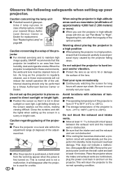
...that this can affect the longevity of the projector is secured carefully to avoid personal injury caused by a Sharp Authorized Service Center or Dealer. I The storage...projector I Protect the lens so as the projector is used for long hours will return the projector to hard impact and/or vibration. Observe the following safeguards when setting up the projector...projector is regularly cleaned, use the projector in high-altitude areas such as mountains (at altitudes of temperature. When using the projector in high-altitude areas with extremes of approximately 4,900 feet (1,500...
...that this can affect the longevity of the projector is secured carefully to avoid personal injury caused by a Sharp Authorized Service Center or Dealer. I The storage...projector I Protect the lens so as the projector is used for long hours will return the projector to hard impact and/or vibration. Observe the following safeguards when setting up the projector...projector is regularly cleaned, use the projector in high-altitude areas such as mountains (at altitudes of temperature. When using the projector in high-altitude areas with extremes of approximately 4,900 feet (1,500...
DT-500 Operation Manual
Page 10
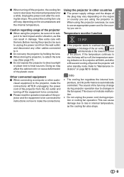
The period the cooling fan runs will vary, depending on the region or country you are using the projector in. Take extra care with the lens. Using the projector in internal temperature, as this can cause damage due to hard impact and/or vibration, as the cooling fan also stops. 9 ing... due to decrease the internal temperature for a while. Introduction I When turning off , the temperature warn- I When storing the projector, re-attach the lens cap. (See page 11). Doing so may change during projection or cooling fan operation. I Please read the operation manuals of the plug...
The period the cooling fan runs will vary, depending on the region or country you are using the projector in. Take extra care with the lens. Using the projector in internal temperature, as this can cause damage due to hard impact and/or vibration, as the cooling fan also stops. 9 ing... due to decrease the internal temperature for a while. Introduction I When turning off , the temperature warn- I When storing the projector, re-attach the lens cap. (See page 11). Doing so may change during projection or cooling fan operation. I Please read the operation manuals of the plug...
DT-500 Operation Manual
Page 11
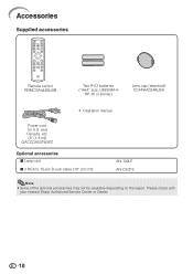
Accessories Supplied accessories Remote control RRMCGA444WJSB Two R-03 batteries ("AAA" size, UM/SUM-4, HP-16 or similar) Lens cap (attached) CCAPHA024WJSA • Operation manual Power cord for U.S. Please check with your nearest Sharp Authorized Service Center or Dealer. 10 and Canada, etc. (6' (1.8 m)) QACCDA007WJPZ Optional accessories I Lamp unit I 3 RCA to 15-pin D-sub cable (10' (3.0 m)) AN-100LP AN-C3CP2 Note • Some of the optional accessories may not be available depending on the region.
Accessories Supplied accessories Remote control RRMCGA444WJSB Two R-03 batteries ("AAA" size, UM/SUM-4, HP-16 or similar) Lens cap (attached) CCAPHA024WJSA • Operation manual Power cord for U.S. Please check with your nearest Sharp Authorized Service Center or Dealer. 10 and Canada, etc. (6' (1.8 m)) QACCDA007WJPZ Optional accessories I Lamp unit I 3 RCA to 15-pin D-sub cable (10' (3.0 m)) AN-100LP AN-C3CP2 Note • Some of the optional accessories may not be available depending on the region.
DT-500 Operation Manual
Page 12
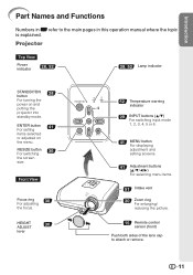
... and Functions Numbers in this operation manual where the topic is explained. ENTER button 41 For setting items selected or adjusted on and putting the projector into standby mode. HEIGHT 30 ADJUST lever 52 Temperature warning indicator 29 INPUT buttons (P/R) For switching input mode 1, 2, 3, 4, 5 or 6. 41 MENU ... menu items. 51 Intake vent 30 Zoom ring For enlarging/ reducing the picture. 15 Remote control sensor (front) Push both sides of the lens cap to the main pages in Z refer to attach or remove. 11 Front View Focus ring 30 For adjusting the focus. RESIZE button 36...
... and Functions Numbers in this operation manual where the topic is explained. ENTER button 41 For setting items selected or adjusted on and putting the projector into standby mode. HEIGHT 30 ADJUST lever 52 Temperature warning indicator 29 INPUT buttons (P/R) For switching input mode 1, 2, 3, 4, 5 or 6. 41 MENU ... menu items. 51 Intake vent 30 Zoom ring For enlarging/ reducing the picture. 15 Remote control sensor (front) Push both sides of the lens cap to the main pages in Z refer to attach or remove. 11 Front View Focus ring 30 For adjusting the focus. RESIZE button 36...
DT-500 Operation Manual
Page 17
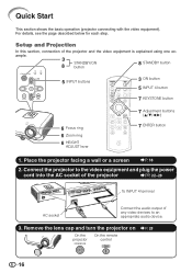
...lens cap and turn the projector on _P. 28 On the On the remote projector control 16 ample. 3 STANDBY/ON 8 button 8 STANDBY button 5 INPUT buttons 3 ON button 5 INPUT 4 button 7 KEYSTONE button 6 Focus ring 6 Zoom ring 6 HEIGHT ADJUST lever 7 Adjustment (P/R/O/Q) buttons 7 ENTER button 1. Connect the projector... to the video equipment and plug the power cord into the AC socket of the projector _PP. 22-28 To INPUT 4 terminal AC socket Connect the audio output of the...
...lens cap and turn the projector on _P. 28 On the On the remote projector control 16 ample. 3 STANDBY/ON 8 button 8 STANDBY button 5 INPUT buttons 3 ON button 5 INPUT 4 button 7 KEYSTONE button 6 Focus ring 6 Zoom ring 6 HEIGHT ADJUST lever 7 Adjustment (P/R/O/Q) buttons 7 ENTER button 1. Connect the projector... to the video equipment and plug the power cord into the AC socket of the projector _PP. 22-28 To INPUT 4 terminal AC socket Connect the audio output of the...
DT-500 Operation Manual
Page 19
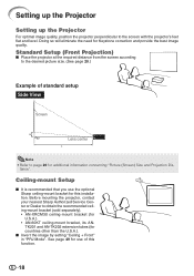
...) Size and Projection Dis- See page 49 for use the optional Sharp ceiling-mount bracket for Keystone correction and provide the best image quality. Standard Setup (Front Projection) I Place the projector at the required distance from the screen according to page 20 for...Lens center L Note • Refer to the desired picture size. (See page 20.) Example of this installation. tance". Ceiling-mount Setup I Invert the image by setting "Ceiling + Front" in "PRJ Mode". Doing so will eliminate the need for this function. 18 Before mounting the projector, contact your nearest Sharp...
...) Size and Projection Dis- See page 49 for use the optional Sharp ceiling-mount bracket for Keystone correction and provide the best image quality. Standard Setup (Front Projection) I Place the projector at the required distance from the screen according to page 20 for...Lens center L Note • Refer to the desired picture size. (See page 20.) Example of this installation. tance". Ceiling-mount Setup I Invert the image by setting "Ceiling + Front" in "PRJ Mode". Doing so will eliminate the need for this function. 18 Before mounting the projector, contact your nearest Sharp...

DT-500 Operation Manual
Page 21
....) (in/cm) L: Projection distance (ft/m) L1: Minimum projection distance (ft/m) L2: Maximum projection distance (ft/m) H: Distance from the lens center to the bottom of the image (in/cm) S: Adjustable range of the projector to the screen. The formula for picture size and projection distance [Feet/inches] [m/cm] L1 (ft) = 0.03694χ / 0.3048...
....) (in/cm) L: Projection distance (ft/m) L1: Minimum projection distance (ft/m) L2: Maximum projection distance (ft/m) H: Distance from the lens center to the bottom of the image (in/cm) S: Adjustable range of the projector to the screen. The formula for picture size and projection distance [Feet/inches] [m/cm] L1 (ft) = 0.03694χ / 0.3048...

DT-500 Operation Manual
Page 22
...1032; 3Љ (2.2 m) 8Ј 5Љ (2.6 m) 6Ј 4Љ (1.9 m) 7Ј 4Љ (2.2 m) 5Ј 5Љ (1.7 m) 6Ј 4Љ (1.9 m) 3Ј 8Љ (1.1 m) 4Ј 2Љ (1.3 m) Distance from the lens center to the bottom of the image [H] 19 5/16Љ (49 cm) 17 3/8Љ (44 cm) 16 3/32Љ (41 cm) 12 7/8Љ (33 cm...cm) L: Projection distance (ft/m) L1: Minimum projection distance (ft/m) L2: Maximum projection distance (ft/m) H: Distance from the lens center to the bottom of the image (in/cm) S: Adjustable range of error in the values in /cm) See page ...
...1032; 3Љ (2.2 m) 8Ј 5Љ (2.6 m) 6Ј 4Љ (1.9 m) 7Ј 4Љ (2.2 m) 5Ј 5Љ (1.7 m) 6Ј 4Љ (1.9 m) 3Ј 8Љ (1.1 m) 4Ј 2Љ (1.3 m) Distance from the lens center to the bottom of the image [H] 19 5/16Љ (49 cm) 17 3/8Љ (44 cm) 16 3/32Љ (41 cm) 12 7/8Љ (33 cm...cm) L: Projection distance (ft/m) L1: Minimum projection distance (ft/m) L2: Maximum projection distance (ft/m) H: Distance from the lens center to the bottom of the image (in/cm) S: Adjustable range of error in the values in /cm) See page ...
DT-500 Operation Manual
Page 29
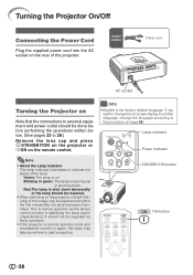
... lamp should be replaced. • When switching on the rear of the lamp. This is normal operation as faulty operation. • If the projector is on page 50. Info • English is stabilising the lamp output characteristics. Lamp indicator Power indicator Note • About the Lamp Indicator The... procedure on . It should be done before performing the operations written below. (See pages 23 to 28.) Remove the lens cap and press S STANDBY/ON on the projector or bON on again, the lamp may be experienced within the first minute after the lamp has been illuminated. Turning the...
... lamp should be replaced. • When switching on the rear of the lamp. This is normal operation as faulty operation. • If the projector is on page 50. Info • English is stabilising the lamp output characteristics. Lamp indicator Power indicator Note • About the Lamp Indicator The... procedure on . It should be done before performing the operations written below. (See pages 23 to 28.) Remove the lens cap and press S STANDBY/ON on the projector or bON on again, the lamp may be experienced within the first minute after the lamp has been illuminated. Turning the...

DT-500 Operation Manual
Page 32
...projector level. • The projector is adjustable ±1 degree from the standard position. Rear adjustment foot Basic Operation 31 Follow the procedures in the area between the adjustment foot and the projector. • Hold the projector firmly while lifting or carrying. • Do not hold by the lens... area. Note • When adjusting the height of the projector, trapezoidal distortion occurs.
...projector level. • The projector is adjustable ±1 degree from the standard position. Rear adjustment foot Basic Operation 31 Follow the procedures in the area between the adjustment foot and the projector. • Hold the projector firmly while lifting or carrying. • Do not hold by the lens... area. Note • When adjusting the height of the projector, trapezoidal distortion occurs.

DT-500 Operation Manual
Page 52
...mode. I Do not use volatile agents such as these can easily get damaged, be sure to the projector for cleaning the lens. Cleaning the lens I As the surface of the projector. Mild detergent diluted with water Appendix Mild detergent Wax Thinner Info • If you have unplugged the ... use any liquid type cleaning agents, as the operation panel is hard to test on a small, inconspicuous area on the projector. I Use a commercially available blower or lens cleaning paper (for glasses and camera lenses) for long periods. The effects of some of plastic. I The cabinet as...
...mode. I Do not use volatile agents such as these can easily get damaged, be sure to the projector for cleaning the lens. Cleaning the lens I As the surface of the projector. Mild detergent diluted with water Appendix Mild detergent Wax Thinner Info • If you have unplugged the ... use any liquid type cleaning agents, as the operation panel is hard to test on a small, inconspicuous area on the projector. I Use a commercially available blower or lens cleaning paper (for glasses and camera lenses) for long periods. The effects of some of plastic. I The cabinet as...
DT-500 Operation Manual
Page 60
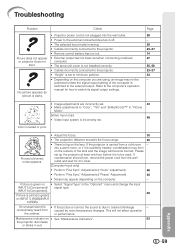
Troubleshooting Problem Check Picure does not appear or projector does not start. Picture is green on • Select "Signal Type" in "Picture Mode". (Video Input only) 48 • Video input system is pink (no green) on the lens. This will become blurred. Page 28 - 29 23-27 14 ...Picture is due to switch its signal output settings. or performance. If the projector is set up the projector at least one hour before it to be projected unless the signal output setting of the lens and the image will not affect operation the cabinet. If condensation should form, ...
Troubleshooting Problem Check Picure does not appear or projector does not start. Picture is green on • Select "Signal Type" in "Picture Mode". (Video Input only) 48 • Video input system is pink (no green) on the lens. This will become blurred. Page 28 - 29 23-27 14 ...Picture is due to switch its signal output settings. or performance. If the projector is set up the projector at least one hour before it to be projected unless the signal output setting of the lens and the image will not affect operation the cabinet. If condensation should form, ...
DT-500 Operation Manual
Page 62
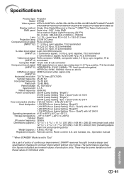
... from these values in individual units. 61 Appendix of continuous improvement, SHARP reserves the right to "Eco" As a part of policy of dots: 983,040 dots (1280 [H] × 768 [V]) Lens 1-1.15 × zoom lens, F2.4-2.6, f = 19.0-21.9 mm Projection lamp 275 W DC...TTL level (positive/negative) VERTICAL SYNC. The performance specification figures indicated are nominal values of production units. Specifications Product type Projector Model DT-500 Video system NTSC3.58/NTSC4.43/PAL/PAL-M/PAL-N/PAL-60/SECAM/DTV480I/DTV480P/ DTV540P/DTV576I/DTV576P/DTV720P/DTV1035I/DTV1080I/DTV1080I...
... from these values in individual units. 61 Appendix of continuous improvement, SHARP reserves the right to "Eco" As a part of policy of dots: 983,040 dots (1280 [H] × 768 [V]) Lens 1-1.15 × zoom lens, F2.4-2.6, f = 19.0-21.9 mm Projection lamp 275 W DC...TTL level (positive/negative) VERTICAL SYNC. The performance specification figures indicated are nominal values of production units. Specifications Product type Projector Model DT-500 Video system NTSC3.58/NTSC4.43/PAL/PAL-M/PAL-N/PAL-60/SECAM/DTV480I/DTV480P/ DTV540P/DTV576I/DTV576P/DTV720P/DTV1035I/DTV1080I/DTV1080I...

DT-500 Operation Manual
Page 64
... Keystone Correction 32 Lamp 10, 54 Lamp indicator 52 Lamp Setting 45 Lamp Timer (Life 49 Lamp unit 55 Language (on-screen display language) ...... 50 Lens cap 11 MENU button 41 ON button 28 Optional accessories 10 OSD Display 48 Overscan 47 Phase 46 Picture Adjustment 43 Picture Mode 38, 43... 15 Replacing the lamp 54, 55 Resize 36, 37 RESIZE button 36 RETURN button 41 RGB/COMP. button 48 RS-232C Setting 50 Saturation 44 Sharp 43 SIDE BAR 36, 37 Special Modes 46 STANDBY button 29 STANDBY/ON button 28, 29 STANDBY Mode 50 STRETCH 36, 37 Subtitle 47 Supplied...
... Keystone Correction 32 Lamp 10, 54 Lamp indicator 52 Lamp Setting 45 Lamp Timer (Life 49 Lamp unit 55 Language (on-screen display language) ...... 50 Lens cap 11 MENU button 41 ON button 28 Optional accessories 10 OSD Display 48 Overscan 47 Phase 46 Picture Adjustment 43 Picture Mode 38, 43... 15 Replacing the lamp 54, 55 Resize 36, 37 RESIZE button 36 RETURN button 41 RGB/COMP. button 48 RS-232C Setting 50 Saturation 44 Sharp 43 SIDE BAR 36, 37 Special Modes 46 STANDBY button 29 STANDBY/ON button 28, 29 STANDBY Mode 50 STRETCH 36, 37 Subtitle 47 Supplied...
