

User Manual (user Manual) (ver.1.0) (English)
Page 2
...unauthorized changes or modifications to this equipment may be connected to the grounding system of plug to operate it. As an ENERGY STAR Partner, Samsung Electronics America, Inc. Caution: To prevent electric shock, match the wide blade of the building as practical. Caution: FCC/CSA regulations ...model meets the ENERGY STAR guidelines for proper grounding and, in particular, specifies that the cable ground shall be in violation of copyrighted TV programs is dangerous to rain or moisture. copyright laws. To prevent damage which may result in part may void the user's authority to...
...unauthorized changes or modifications to this equipment may be connected to the grounding system of plug to operate it. As an ENERGY STAR Partner, Samsung Electronics America, Inc. Caution: To prevent electric shock, match the wide blade of the building as practical. Caution: FCC/CSA regulations ...model meets the ENERGY STAR guidelines for proper grounding and, in particular, specifies that the cable ground shall be in violation of copyrighted TV programs is dangerous to rain or moisture. copyright laws. To prevent damage which may result in part may void the user's authority to...

User Manual (user Manual) (ver.1.0) (English)
Page 3
...in the operating instructions. • Follow all safety and operating instructions before operating your TV receiver only from the wall outlet before cleaning. We are proud to offer you for choosing Samsung! Such additions can fall. Important Safety Information Always be careful when using , and ...provide convenient, dependable service and enjoyment for years to come. Thank You for Choosing Samsung Thank you a product that there is equipped with slots in television technology. do not place the TV receiver on the marking label. If the plug still does not fit, contact your...
...in the operating instructions. • Follow all safety and operating instructions before operating your TV receiver only from the wall outlet before cleaning. We are proud to offer you for choosing Samsung! Such additions can fall. Important Safety Information Always be careful when using , and ...provide convenient, dependable service and enjoyment for years to come. Thank You for Choosing Samsung Thank you a product that there is equipped with slots in television technology. do not place the TV receiver on the marking label. If the plug still does not fit, contact your...
User Manual (user Manual) (ver.1.0) (English)
Page 4
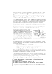
...characteristics as to grounding electrodes, and requirements for long periods of time. Unauthorized substitutions may cause undesired operation. if the TV does not operate normally by the manufacturer or those controls that may result in performance • If you make adjustments ...be walked on or pinched by the operating instructions. EXAMPLE OF ANTENNA GROUNDING GROUND CLAMP ELECTRIC SERVICE EQUIPMENT NEC - when the TV exhibits a distinct change in additional damage to the unit. • Upon completion of antenna discharge unit, connection to provide some...
...characteristics as to grounding electrodes, and requirements for long periods of time. Unauthorized substitutions may cause undesired operation. if the TV does not operate normally by the manufacturer or those controls that may result in performance • If you make adjustments ...be walked on or pinched by the operating instructions. EXAMPLE OF ANTENNA GROUNDING GROUND CLAMP ELECTRIC SERVICE EQUIPMENT NEC - when the TV exhibits a distinct change in additional damage to the unit. • Upon completion of antenna discharge unit, connection to provide some...
User Manual (user Manual) (ver.1.0) (English)
Page 6
... Antennas 14 Antennas with 300-ohm Flat Twin Leads 14 Antennas with 75-ohm Round Leads 15 Separate VHF and UHF Antennas 15 Connecting Cable TV 15 Cable without a Cable Box 15 Connecting to a Cable Box that Descrambles All Channels . . . . 16 Connecting to a Cable Box that Descrambles Some Channels. ... 33 Setting the Clock 34 Option 1: Setting the Clock Manually 34 Option 2: Using the Local PBS Channel to Automatically Set the TV Clock 35 Customizing the Picture 37 Using Automatic Picture Settings 38 Customizing the Sound 39 Using Automatic Sound Settings 40 Viewing an External ...
... Antennas 14 Antennas with 300-ohm Flat Twin Leads 14 Antennas with 75-ohm Round Leads 15 Separate VHF and UHF Antennas 15 Connecting Cable TV 15 Cable without a Cable Box 15 Connecting to a Cable Box that Descrambles All Channels . . . . 16 Connecting to a Cable Box that Descrambles Some Channels. ... 33 Setting the Clock 34 Option 1: Setting the Clock Manually 34 Option 2: Using the Local PBS Channel to Automatically Set the TV Clock 35 Customizing the Picture 37 Using Automatic Picture Settings 38 Customizing the Sound 39 Using Automatic Sound Settings 40 Viewing an External ...
User Manual (user Manual) (ver.1.0) (English)
Page 7
...V-Chip (Canada 70 Setting Up Your Personal ID Number (PIN 70 How to Enable/Disable the V-Chip 71 How to Set up Restrictions Using the "TV guidelines 71 How to Set up Restrictions using the MPAA Ratings: G, PG, PG-13, R, NC-17, X 73 How to Set up Restrictions ...Using the Canadian English . . . . 74 How to Set up Restrictions Using the Canadian French . . . 75 How to Reset the TV after the V-Chip Blocks a Channel ("Emergency Escape 76 Viewing the Demonstration 77 Chapter 5: Troubleshooting 78 Identifying Problems 78 Appendix 79 Cleaning and Maintaining Your...
...V-Chip (Canada 70 Setting Up Your Personal ID Number (PIN 70 How to Enable/Disable the V-Chip 71 How to Set up Restrictions Using the "TV guidelines 71 How to Set up Restrictions using the MPAA Ratings: G, PG, PG-13, R, NC-17, X 73 How to Set up Restrictions ...Using the Canadian English . . . . 74 How to Set up Restrictions Using the Canadian French . . . 75 How to Reset the TV after the V-Chip Blocks a Channel ("Emergency Escape 76 Viewing the Demonstration 77 Chapter 5: Troubleshooting 78 Identifying Problems 78 Appendix 79 Cleaning and Maintaining Your...
User Manual (user Manual) (ver.1.0) (English)
Page 8
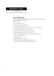
...-to-use remote control • Easy-to-use on-screen menu system • Automatic timer to turn the TV on and off • Adjustable picture and sound settings that can be stored in the TV's memory • Automatic channel tuning for up to 181 channels • A special filter to reduce or eliminate...; Headphone jack for private listening • 16:9 letter box format available depending upon source • Picture in Picture (TXN2798HF/TXN3098WHF/TXN3298HF) 8 Chapter One YOUR NEW TV List of Features Your TV was designed with the latest technology.
...-to-use remote control • Easy-to-use on-screen menu system • Automatic timer to turn the TV on and off • Adjustable picture and sound settings that can be stored in the TV's memory • Automatic channel tuning for up to 181 channels • A special filter to reduce or eliminate...; Headphone jack for private listening • 16:9 letter box format available depending upon source • Picture in Picture (TXN2798HF/TXN3098WHF/TXN3298HF) 8 Chapter One YOUR NEW TV List of Features Your TV was designed with the latest technology.
User Manual (user Manual) (ver.1.0) (English)
Page 9
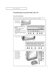
...; TXN2798HF • TXN3298HF • TXN3098WHF • TXN2775HF • TXN3275HF • TXN3075WHF • TXN2745FP • TXN3245FP 9 Is the Power Plug correctly connect- ed to touch the button(using a pen or pencil may not work . 1. YOUR NEW TV Familiarizing Yourself with The TV Front Panel Buttons The buttons on the front panel control your finger...
...; TXN2798HF • TXN3298HF • TXN3098WHF • TXN2775HF • TXN3275HF • TXN3075WHF • TXN2745FP • TXN3245FP 9 Is the Power Plug correctly connect- ed to touch the button(using a pen or pencil may not work . 1. YOUR NEW TV Familiarizing Yourself with The TV Front Panel Buttons The buttons on the front panel control your finger...
User Manual (user Manual) (ver.1.0) (English)
Page 10
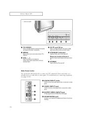
... jacks to connect an A/V component that is used to select items on the onmscreen menu. ¨ CH M and CH L Press to change between viewing TV programs and signals from other components. ´ MENU Press to see pages 13-22.) Œ AUDIO INPUT jacks Used to connect the audio signals from...SUPER VIDEO INPUT jack S-Video signal from an S-VHS VCR or DVD player. ¨ HEADPHONE jack Connect a set of your TV's features. ˇ VOL - , + Press to this spot on the TV. Ø POWER Press to highlight various items on the on-screen menu. ˆ STANDBY indicator Lights up when you turn the...
... jacks to connect an A/V component that is used to select items on the onmscreen menu. ¨ CH M and CH L Press to change between viewing TV programs and signals from other components. ´ MENU Press to see pages 13-22.) Œ AUDIO INPUT jacks Used to connect the audio signals from...SUPER VIDEO INPUT jack S-Video signal from an S-VHS VCR or DVD player. ¨ HEADPHONE jack Connect a set of your TV's features. ˇ VOL - , + Press to this spot on the TV. Ø POWER Press to highlight various items on the on-screen menu. ˆ STANDBY indicator Lights up when you turn the...
User Manual (user Manual) (ver.1.0) (English)
Page 11
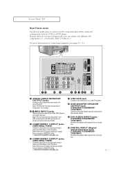
...modes. ´,¨,ˆAV INPUT jacks Video and Audio signals from a monitor in DVD/DTV mode. • TXN2745FP/TXN3245FP: 480i/480p only. Ø COMPONENT 2 INPUT jacks (480i/480p/1080i) Connect to the audio/video input... Interface) jack (TXN3298HF/TXN3098WHF/ TXN2798HF) Receives the digital video signals from a monitor in DVD/DTV mode. • TXN2745FP/TXN3245FP: 480i/480p only. ∏ VHF/UHF jack Connect to an antenna or to connect an A/V component that will...audio and component output jacks of a recording VCR. YOUR NEW TV Rear Panel Jacks Use the rear panel jacks to a cable...
...modes. ´,¨,ˆAV INPUT jacks Video and Audio signals from a monitor in DVD/DTV mode. • TXN2745FP/TXN3245FP: 480i/480p only. Ø COMPONENT 2 INPUT jacks (480i/480p/1080i) Connect to the audio/video input... Interface) jack (TXN3298HF/TXN3098WHF/ TXN2798HF) Receives the digital video signals from a monitor in DVD/DTV mode. • TXN2745FP/TXN3245FP: 480i/480p only. ∏ VHF/UHF jack Connect to an antenna or to connect an A/V component that will...audio and component output jacks of a recording VCR. YOUR NEW TV Rear Panel Jacks Use the rear panel jacks to a cable...
User Manual (user Manual) (ver.1.0) (English)
Page 12
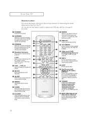
... your personal, customized sound settings). ˇ P.MODE Adjust the TV picture by the Samsung remote control (i.e., TV, Set Top Box, VCR, Cable box, or DVD). PRE-CH Tunes to the previous channel. Ò TV/VIDEO Press to display all of the preset factory settings (or ...and CHM (Channel Up/Down) Press CHL or CHM to change ) a particular item. ¯ TURBO (TXN2771HF/TXN3071WHF/ TXN3271HF/TXN2670WHF/ TXN2775HF/TXN3275HF/ TXN3075WHF/TXN2745FP/ TXN3245FP/TXN3234HF) Press to turn the TURBO sound On or Off. ˘ MTS (Multichannel Television Stereo) Press to see the time, channel, etc.,...
... your personal, customized sound settings). ˇ P.MODE Adjust the TV picture by the Samsung remote control (i.e., TV, Set Top Box, VCR, Cable box, or DVD). PRE-CH Tunes to the previous channel. Ò TV/VIDEO Press to display all of the preset factory settings (or ...and CHM (Channel Up/Down) Press CHL or CHM to change ) a particular item. ¯ TURBO (TXN2771HF/TXN3071WHF/ TXN3271HF/TXN2670WHF/ TXN2775HF/TXN3275HF/ TXN3075WHF/TXN2745FP/ TXN3245FP/TXN3234HF) Press to turn the TURBO sound On or Off. ˘ MTS (Multichannel Television Stereo) Press to see the time, channel, etc.,...

User Manual (user Manual) (ver.1.0) (English)
Page 13
... window. SWAP Exchanges the video signal that is not functioning properly, take out the batteries and press the reset button for about 2~3 seconds. YOUR NEW TV Remote Control ¿ TV/COMPONENT Press to fast forward the tape in the PIP window only). - FF Press to switch the...
... window. SWAP Exchanges the video signal that is not functioning properly, take out the batteries and press the reset button for about 2~3 seconds. YOUR NEW TV Remote Control ¿ TV/COMPONENT Press to fast forward the tape in the PIP window only). - FF Press to switch the...
User Manual (user Manual) (ver.1.0) (English)
Page 15
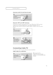
... to view unscrambled cable channels. 15 Separate VHF and UHF Antennas If you have two separate antennas for your TV (one VHF and one UHF), you do not need a cable box to the TV. This procedure requires an optional combiner-adaptor (available at most electronics shops). 1 Connect both antenna leads to a cable... connect to the combiner. 2 Plug the combiner into the VHF/UHF antenna terminal on back of the TV. Cable without a Cable Box 1 Plug the incoming cable into the VHF/UHF terminal on the bottom of the back panel. INSTALLATION Antennas with 75-ohm ...
... to view unscrambled cable channels. 15 Separate VHF and UHF Antennas If you have two separate antennas for your TV (one VHF and one UHF), you do not need a cable box to the TV. This procedure requires an optional combiner-adaptor (available at most electronics shops). 1 Connect both antenna leads to a cable... connect to the combiner. 2 Plug the combiner into the VHF/UHF antenna terminal on back of the TV. Cable without a Cable Box 1 Plug the incoming cable into the VHF/UHF terminal on the bottom of the back panel. INSTALLATION Antennas with 75-ohm ...
User Manual (user Manual) (ver.1.0) (English)
Page 16
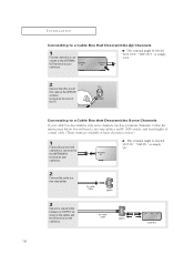
... is connected to the ANTENNA IN terminal on your cable box. You will need a two-way splitter, an RF (A/B) switch, and four lengths of the TV. INSTALLATION Connecting to a Cable Box that Descrambles All Channels 1 Find the cable that is connected to the ANTENNA OUT terminal on your cable box. M This...
... is connected to the ANTENNA IN terminal on your cable box. You will need a two-way splitter, an RF (A/B) switch, and four lengths of the TV. INSTALLATION Connecting to a Cable Box that Descrambles All Channels 1 Find the cable that is connected to the ANTENNA OUT terminal on your cable box. M This...
User Manual (user Manual) (ver.1.0) (English)
Page 17
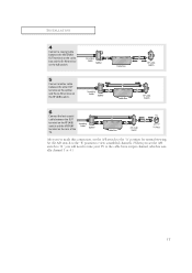
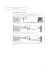
Set the A/B switch to the "B" position to view scrambled channels. (When you will need to tune your TV to the "A" position for normal viewing. After you've made this connection, set the A/B switch to "B," you set the A/B switch to the cable box's output ... RF (A/B) switch. 6 Connect the last coaxial cable between the OUT terminal on the RF (A/B) switch and the VHF/UHF terminal on the rear of the TV.
Set the A/B switch to the "B" position to view scrambled channels. (When you will need to tune your TV to the "A" position for normal viewing. After you've made this connection, set the A/B switch to "B," you set the A/B switch to the cable box's output ... RF (A/B) switch. 6 Connect the last coaxial cable between the OUT terminal on the RF (A/B) switch and the VHF/UHF terminal on the rear of the TV.
User Manual (user Manual) (ver.1.0) (English)
Page 18
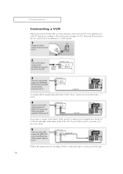
.... 18 Skip step 1 if you have not yet connected to an antenna or a cable system. 1 Unplug the cable or antenna from the back of the TV. 2 Connect the cable or antenna to the left and right audio input jacks of the VCR. 3 Connect a coaxial cable between the VIDEO OUT jack on... the VCR and the VIDEO jack(AV1~AV3) on the TV. If you have a "mono" (non-stereo) VCR, use the Y-connector (not supplied) to hook up to the ANTENNA IN terminal on the back of the...
.... 18 Skip step 1 if you have not yet connected to an antenna or a cable system. 1 Unplug the cable or antenna from the back of the TV. 2 Connect the cable or antenna to the left and right audio input jacks of the VCR. 3 Connect a coaxial cable between the VIDEO OUT jack on... the VCR and the VIDEO jack(AV1~AV3) on the TV. If you have a "mono" (non-stereo) VCR, use the Y-connector (not supplied) to hook up to the ANTENNA IN terminal on the back of the...
User Manual (user Manual) (ver.1.0) (English)
Page 19
... underneath the number "1." 3 Connect an S-video cable between the AUDIO OUT jacks on the VCR and the AUDIO INPUT 1 jacks on the TV. INSTALLATION Connecting an S-VHS VCR Your TV can be connected to an S-Video signal from an S-VHS VCR. (This connection delivers a better picture as compared to a standard VHS VCR... or cable to your VCR and your local electronics store.) 19 An S-video cable is usually included with an S-VHS VCR. (If not, check your TV. 2 Connect a set of audio cables between the S-VIDEO OUT jack on the VCR and the S-VIDEO INPUT jack on the...
... underneath the number "1." 3 Connect an S-video cable between the AUDIO OUT jacks on the VCR and the AUDIO INPUT 1 jacks on the TV. INSTALLATION Connecting an S-VHS VCR Your TV can be connected to an S-Video signal from an S-VHS VCR. (This connection delivers a better picture as compared to a standard VHS VCR... or cable to your VCR and your local electronics store.) 19 An S-video cable is usually included with an S-VHS VCR. (If not, check your TV. 2 Connect a set of audio cables between the S-VIDEO OUT jack on the VCR and the S-VIDEO INPUT jack on the...
User Manual (user Manual) (ver.1.0) (English)
Page 20
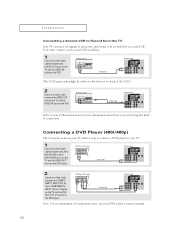
... Component video, see your second VCR as follows: 1 Connect a set of audio cables between the AV-2 INPUT(VCR) or AV-3 INPUT(VCR) jacks on the TV and the AUDIO OUT jacks on the DVD player. 2 Connect a video cable between the COMPONENT 1 INPUT (Y/V, PB, PR) or COMPONENT 2 INPUT (Y/V, PB, PR)jacks on... the DVDOUT (Y, PB, PR) jacks on the DVD player. To do this kind of connection. INSTALLATION Connecting a Second VCR to Record from the TV Your TV can send out signals of its picture and sound to be either on the front or on back of the VCR.) 2 Connect a video cable between ...
... Component video, see your second VCR as follows: 1 Connect a set of audio cables between the AV-2 INPUT(VCR) or AV-3 INPUT(VCR) jacks on the TV and the AUDIO OUT jacks on the DVD player. 2 Connect a video cable between the COMPONENT 1 INPUT (Y/V, PB, PR) or COMPONENT 2 INPUT (Y/V, PB, PR)jacks on... the DVDOUT (Y, PB, PR) jacks on the DVD player. To do this kind of connection. INSTALLATION Connecting a Second VCR to Record from the TV Your TV can send out signals of its picture and sound to be either on the front or on back of the VCR.) 2 Connect a video cable between ...
User Manual (user Manual) (ver.1.0) (English)
Page 21
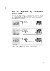
Next, connect the Left and Right audio from the set-top box to the corresponding L and R terminals on the TV. (The connections for a typical set-top box are shown below.) • TXN2745FP/TXN3245FP: 480p only. 1 Connect a coaxial cable between the ANTENNA OUT terminal on the Set Top Box and the ...antenna terminal on the TV. 2 Connect a set -top box to their corresponding inputs on the Set Top Box. Note: For ...
Next, connect the Left and Right audio from the set-top box to the corresponding L and R terminals on the TV. (The connections for a typical set-top box are shown below.) • TXN2745FP/TXN3245FP: 480p only. 1 Connect a coaxial cable between the ANTENNA OUT terminal on the Set Top Box and the ...antenna terminal on the TV. 2 Connect a set -top box to their corresponding inputs on the Set Top Box. Note: For ...

User Manual (user Manual) (ver.1.0) (English)
Page 22
... DVI OUT jack on the screen in order to 1080I OR 480P. Set the DTV decoder DIGITAL OUTPUT jack output setting to digitally connect the TV with 1080i and 480p picture signals. Note • The DIGITAL INPUT jack can be use in the future when High-bandwidth Digital Content Protection ... D-VHS are put on the market.) 1 Connect a coaxial cable between the ANTENNA OUT terminal on the Set Top Box and the antenna terminal on the TV. 2 Connect a set of a personal computer. • Use a DVI 25-pin cable (commercially available) in their digital form. (This DIGITAL INPUT jack is for use with...
... DVI OUT jack on the screen in order to 1080I OR 480P. Set the DTV decoder DIGITAL OUTPUT jack output setting to digitally connect the TV with 1080i and 480p picture signals. Note • The DIGITAL INPUT jack can be use in the future when High-bandwidth Digital Content Protection ... D-VHS are put on the market.) 1 Connect a coaxial cable between the ANTENNA OUT terminal on the Set Top Box and the antenna terminal on the TV. 2 Connect a set of a personal computer. • Use a DVI 25-pin cable (commercially available) in their digital form. (This DIGITAL INPUT jack is for use with...
User Manual (user Manual) (ver.1.0) (English)
Page 23
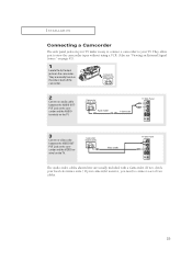
...camcorder to connect a set of the camcorder. 2 Connect an audio cable between the AUDIO OUTPUT jack on the camcorder and the AUDIO terminals on the TV. 3 Connect a video cable between the VIDEO OUTPUT jack on the camcorder and the VIDEO terminal on the camcorder. They are usually included with a Camcorder...the camcorder tapes without using a VCR. (Also see "Viewing an External Signal Source" on page 41). 1 Locate the A/V output jacks on the TV. The audio-video cables shown here are usually found on the side or back of two cables. 23 INSTALLATION Connecting a Camcorder The side panel jacks...
...camcorder to connect a set of the camcorder. 2 Connect an audio cable between the AUDIO OUTPUT jack on the camcorder and the AUDIO terminals on the TV. 3 Connect a video cable between the VIDEO OUTPUT jack on the camcorder and the VIDEO terminal on the camcorder. They are usually included with a Camcorder...the camcorder tapes without using a VCR. (Also see "Viewing an External Signal Source" on page 41). 1 Locate the A/V output jacks on the TV. The audio-video cables shown here are usually found on the side or back of two cables. 23 INSTALLATION Connecting a Camcorder The side panel jacks...


