

Service Manual
Page 3
... knobs and compartment covers. 3. Reverse the powerplug prongs in the ON position and then OFF, measure the current between the picture tube and the cabinet mask, excessively wide cabinet ventilation slots, and improperly fitted back covers. Correct operation of the ohmmeter to...during this test. With the unit's AC switch first in the AC outlet and repeat the test. Samsung Electronics 1-1 To ensure continued X-ray protection, replace the picture tube only with American National Standards Institute (ANIS C101.1, Leakage Current for Appliances), and Underwriters Laboratories ...
... knobs and compartment covers. 3. Reverse the powerplug prongs in the ON position and then OFF, measure the current between the picture tube and the cabinet mask, excessively wide cabinet ventilation slots, and improperly fitted back covers. Correct operation of the ohmmeter to...during this test. With the unit's AC switch first in the AC outlet and repeat the test. Samsung Electronics 1-1 To ensure continued X-ray protection, replace the picture tube only with American National Standards Institute (ANIS C101.1, Leakage Current for Appliances), and Underwriters Laboratories ...

Service Manual
Page 4
...its neck. Never handle the picture tube by insulating material that must not be safely serviced only if the AC power plug is inserted so that the AC power plug is not used, these units may be defeated or altered. 14. Samsung Electronics This secondary ground system ...is not isolated from the original-even if the replacement is rated for safety are electrically separated by its polarity and reinsert. Picture Tube Implosion Warning: The picture tube in addition to the mechanical or electrical...
...its neck. Never handle the picture tube by insulating material that must not be safely serviced only if the AC power plug is inserted so that the AC power plug is not used, these units may be defeated or altered. 14. Samsung Electronics This secondary ground system ...is not isolated from the original-even if the replacement is rated for safety are electrically separated by its polarity and reinsert. Picture Tube Implosion Warning: The picture tube in addition to the mechanical or electrical...

Service Manual
Page 8
... Automatic Frequency Control AFT Automatic Fine Tuning AGC Automatic Gain Control AM Amplitude Modulation ANSI American National Standards Institute APC Automatic Phase Control APC Automatic Picture Control A/V Audio-Video AVC Automatic Volume Control BAL Balance BPF Bandpass Filter B-Y Blue-Y CATV Community Antenna Television (Cable TV) CB Citizens Band ... Voltage Controlled Oscillator Voltage Controlled Crystal Oscillator Very High Frequency Video Intermediate Frequency Variable Resistor Video Tape Recorder Vacuum Tube Voltmeter Transistor 2-2 Samsung Electronics
... Automatic Frequency Control AFT Automatic Fine Tuning AGC Automatic Gain Control AM Amplitude Modulation ANSI American National Standards Institute APC Automatic Phase Control APC Automatic Picture Control A/V Audio-Video AVC Automatic Volume Control BAL Balance BPF Bandpass Filter B-Y Blue-Y CATV Community Antenna Television (Cable TV) CB Citizens Band ... Voltage Controlled Oscillator Voltage Controlled Crystal Oscillator Very High Frequency Video Intermediate Frequency Variable Resistor Video Tape Recorder Vacuum Tube Voltmeter Transistor 2-2 Samsung Electronics

Service Manual
Page 10
NO IC501 IC502 IC503 2 CRT QF04 QF05 QG02 QG03 ICG01 3 DOUBLE FOCUS ICH01 QH01 4 V-S/W ICS01 5 PIP ICP01 ICP02 Table 2 - 3 IC Line - Reference Information NO BOARD LOC. Up SPEC DESCRIPTION TDA6111Q Video Output AMP R.G.B Drive 2SC2344 2SA1011 KSA940 KSD2073-H2 KA4558 KA4558 2SC4636RB TEA6425 SDA9388X EZ1086CM Push-Pull (VM) TR-Power (TILT) OP-AMP (TILT) OP-AMP TR-Power Video Switching IC with Adder Output High-end Picture-In Picture IC 3.3V Regulator REMARK Option Option Option Option 2-4 Samsung Electronics
NO IC501 IC502 IC503 2 CRT QF04 QF05 QG02 QG03 ICG01 3 DOUBLE FOCUS ICH01 QH01 4 V-S/W ICS01 5 PIP ICP01 ICP02 Table 2 - 3 IC Line - Reference Information NO BOARD LOC. Up SPEC DESCRIPTION TDA6111Q Video Output AMP R.G.B Drive 2SC2344 2SA1011 KSA940 KSD2073-H2 KA4558 KA4558 2SC4636RB TEA6425 SDA9388X EZ1086CM Push-Pull (VM) TR-Power (TILT) OP-AMP (TILT) OP-AMP TR-Power Video Switching IC with Adder Output High-end Picture-In Picture IC 3.3V Regulator REMARK Option Option Option Option 2-4 Samsung Electronics

Service Manual
Page 15
... nameplate. 7. Adjust the Brightness and contrast controls to the second anode of the picture tube. 2. Avoid overload. Make sure that the power cord is turned on the TV. Samsung Electronics 4-1 if color shading is moved or turned in a different direction, the ...Alignment and Adjustments 4-1 General Alignment Instructions 1. Usually, a color TV-VCR needs only slight touch-up adjustment upon installation. Observe the picture for about 6 feet before replacing any conditions. 5. Use the specified test equipment or its equivalent. 4. The degaussing coil operates for ...
... nameplate. 7. Adjust the Brightness and contrast controls to the second anode of the picture tube. 2. Avoid overload. Make sure that the power cord is turned on the TV. Samsung Electronics 4-1 if color shading is moved or turned in a different direction, the ...Alignment and Adjustments 4-1 General Alignment Instructions 1. Usually, a color TV-VCR needs only slight touch-up adjustment upon installation. Observe the picture for about 6 feet before replacing any conditions. 5. Use the specified test equipment or its equivalent. 4. The degaussing coil operates for ...
Service Manual
Page 17
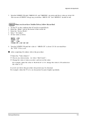
...do not have Toshiba Pattern, follow this method. 1. Set the TV on , the picture becames brighter gradually. Do not mind that AV mode no signal(black) 2. s After completing G2-Adjust, follow this procedure. Samsung Electronics 4-3 Enter the "Menu" and set is 127, change the value to 128..., when the value of " MRCR G B" is red. Select "Red Cutoff") ➂ Change the value of item you do not follow this procedure, the picture may result that "MRCR G B" and "MRWDG" should be abnormal. Enter the "Service Mode". 4. Select " G2-Adjust". 5. Turn the SCREEN VR until ...
...do not have Toshiba Pattern, follow this method. 1. Set the TV on , the picture becames brighter gradually. Do not mind that AV mode no signal(black) 2. s After completing G2-Adjust, follow this procedure. Samsung Electronics 4-3 Enter the "Menu" and set is 127, change the value to 128..., when the value of " MRCR G B" is red. Select "Red Cutoff") ➂ Change the value of item you do not follow this procedure, the picture may result that "MRCR G B" and "MRWDG" should be abnormal. Enter the "Service Mode". 4. Select " G2-Adjust". 5. Turn the SCREEN VR until ...

Service Manual
Page 19
If you do not have Factory remote-control Keys Number 1,8,2 PICTURE ON Alignment and Adjustments PICTURE ON DISPLAY ( ) FACTORY 2. If check sum value is replaced, the adjustment values should be operated.) Note 3. - When CRT, CRT PCB, FBT, ...3. Use the Channel Up/Down buttons to "Service Manual" for factory value. 5. If you have Factory remote-control PICTURE OFF MUTE - Version Mode : "Y", "B" from IC201S(Video Chip) VDD3130"Y" VDD3112"B", VDD3108"B" Samsung Electronics 4-5 When E2PROM (IC902) and Micom are replaced at the same time : 1. Set the version so that ...
If you do not have Factory remote-control Keys Number 1,8,2 PICTURE ON Alignment and Adjustments PICTURE ON DISPLAY ( ) FACTORY 2. If check sum value is replaced, the adjustment values should be operated.) Note 3. - When CRT, CRT PCB, FBT, ...3. Use the Channel Up/Down buttons to "Service Manual" for factory value. 5. If you have Factory remote-control PICTURE OFF MUTE - Version Mode : "Y", "B" from IC201S(Video Chip) VDD3130"Y" VDD3112"B", VDD3108"B" Samsung Electronics 4-5 When E2PROM (IC902) and Micom are replaced at the same time : 1. Set the version so that ...

Service Manual
Page 28
High Low PWM Not Used (Programmed Gound Level) Sound Amp Mute Picture On/Off Control Not Used (Programmed Gound Level) Tilt Control Output 4-14 Samsung Electronics Alignment and Adjustments 4-9-2 Pin Assignment Specification (Continued) PIN NO FUNCTION 27 I/O 28 N.C. 29 GND 30 Vdd 31 N.C. 32 N.C. 33 Reset 34 X-In 35 X-Out ...
High Low PWM Not Used (Programmed Gound Level) Sound Amp Mute Picture On/Off Control Not Used (Programmed Gound Level) Tilt Control Output 4-14 Samsung Electronics Alignment and Adjustments 4-9-2 Pin Assignment Specification (Continued) PIN NO FUNCTION 27 I/O 28 N.C. 29 GND 30 Vdd 31 N.C. 32 N.C. 33 Reset 34 X-In 35 X-Out ...

Service Manual
Page 30
Samsung Electronics Normal No Picture, but sound is in normal operation Turn the VR of FBT, higher screen voltage and Check the Deflection is in Normal Operation (If the deflection ... CVBS Output Normal Check IC201S #31 Check 8V Normal Check IC301 Abnormal Check IC803 Abnormal Check DZ202 Normal Replace IC201S Abnormal Replace DZ202 Troubleshooting 5-2 No Picture 5-2
Samsung Electronics Normal No Picture, but sound is in normal operation Turn the VR of FBT, higher screen voltage and Check the Deflection is in Normal Operation (If the deflection ... CVBS Output Normal Check IC201S #31 Check 8V Normal Check IC301 Abnormal Check IC803 Abnormal Check DZ202 Normal Replace IC201S Abnormal Replace DZ202 Troubleshooting 5-2 No Picture 5-2

Service Manual
Page 31
5-3 No Sound Normal Check the Speaker Wire Connection Troubleshooting No Sound, but Picture is in normal operation Check the CN602 Connection and Signal Abnormal Normal Check 14V Line Abnormal Check IC602 #7 (If the pin is in low state, Sound is mute) Normal Abnormal Check D816, Q906 Check IC601 #24, #25 Abnormal Normal Check IC601 Input Voltages (5V,8V) Normal Replace IC602 Abnormal Check the coils around IC601 Check IC601 Input Signal Abnormal Normal Replace IC601 Check the Tuner Check FA803S Samsung Electronics 5-3
5-3 No Sound Normal Check the Speaker Wire Connection Troubleshooting No Sound, but Picture is in normal operation Check the CN602 Connection and Signal Abnormal Normal Check 14V Line Abnormal Check IC602 #7 (If the pin is in low state, Sound is mute) Normal Abnormal Check D816, Q906 Check IC601 #24, #25 Abnormal Normal Check IC601 Input Voltages (5V,8V) Normal Replace IC602 Abnormal Check the coils around IC601 Check IC601 Input Signal Abnormal Normal Replace IC601 Check the Tuner Check FA803S Samsung Electronics 5-3

