
Service Manual
Page 13
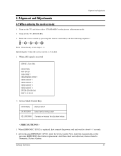
... IC (IC902), enter the Service mode. Samsung Electronics 4-1 Initial display when the service mode is replaced, first connect the power cord and wait for about 4~5 seconds. 2. When EEPROM IC (IC902) is switched. 1. When a RF signal is received SERVICE / Sim-474A DEFLECTION 480P OFFSET 1080i OFFSET CONVERGENCE OFFSET VIDEO ADJUST 1 VIDEO ADJUST 2 VIDEO...
... IC (IC902), enter the Service mode. Samsung Electronics 4-1 Initial display when the service mode is replaced, first connect the power cord and wait for about 4~5 seconds. 2. When EEPROM IC (IC902) is switched. 1. When a RF signal is received SERVICE / Sim-474A DEFLECTION 480P OFFSET 1080i OFFSET CONVERGENCE OFFSET VIDEO ADJUST 1 VIDEO ADJUST 2 VIDEO...
Service Manual
Page 25
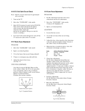
...being adjusted. 3. Green 5. Short F/S Test point (located on the TV. 2. To restore both sound and picture do not appear. Connect a convergence jig and read data. 5. Alignment and Adjustments 4-4-8 Lens Focus Adjustment PRECAUTIONS 1. Input a crosshatch pattern. Crimson Blue - Green lens adjustment: Set ...Note : The F.S. Select the "STANDARD" video mode. 2. Adjust the TV for best possible focus around the horizontal center-line. P L1 L2 Samsung Electronics RED ABERRATION BLUE ABERRATION L1, L2_< P Fig. 4-2 Color Aberration 4-13 Turn on the SUB PCB).
...being adjusted. 3. Green 5. Short F/S Test point (located on the TV. 2. To restore both sound and picture do not appear. Connect a convergence jig and read data. 5. Alignment and Adjustments 4-4-8 Lens Focus Adjustment PRECAUTIONS 1. Input a crosshatch pattern. Crimson Blue - Green lens adjustment: Set ...Note : The F.S. Select the "STANDARD" video mode. 2. Adjust the TV for best possible focus around the horizontal center-line. P L1 L2 Samsung Electronics RED ABERRATION BLUE ABERRATION L1, L2_< P Fig. 4-2 Color Aberration 4-13 Turn on the SUB PCB).
Service Manual
Page 26
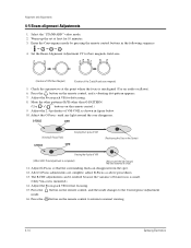
... adjustments can disappear from the spot. 12. Press the button on the remote control, and the mode changes to normal viewing. 4-14 Samsung Electronics Enter the Convergence mode by pressing the remote control buttons in figure below. 10. Adjust the 2, 4 polarities of beam focus is small. (Only Vm...-pack VR for defocusing. 8. Check the squarewave at least for 10 minutes. 3. Press the button on the remote control to return to the Convergence Adjustment mode. 16. Warm up the set at the point where the focus is mounted.) 14. G-FOCUS G-FOCUS CORE CORE (Varying G-Focus ...
... adjustments can disappear from the spot. 12. Press the button on the remote control, and the mode changes to normal viewing. 4-14 Samsung Electronics Enter the Convergence mode by pressing the remote control buttons in figure below. 10. Adjust the 2, 4 polarities of beam focus is small. (Only Vm...-pack VR for defocusing. 8. Check the squarewave at least for 10 minutes. 3. Press the button on the remote control to return to the Convergence Adjustment mode. 16. Warm up the set at the point where the focus is mounted.) 14. G-FOCUS G-FOCUS CORE CORE (Varying G-Focus ...
Service Manual
Page 35
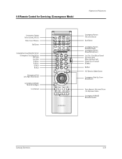
4-8 Remote Control for Servicing (Convergence Mode) Alignment and Adjustments Samsung Electronics 4-23
4-8 Remote Control for Servicing (Convergence Mode) Alignment and Adjustments Samsung Electronics 4-23
Service Manual
Page 36
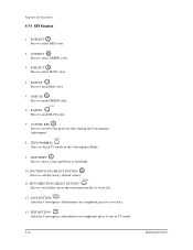
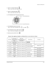
... BUTTON Press to the previous data during the Convergence Adjustment. 8. LINE SHIFT Press to TV mode. 4-24 Samsung Electronics SAVE BUTTON After the Convergence Adjustments are completed, press to save data. 13 EXIT BUTTON After the Convergence adjustments are completed, press to exit to move... direction horizontally or vertically. 12. H/V DIRECTION SELECT BUTTON Press to mute BLUE color. 7. B-SELECT Press to check TV mode in the Convergence Mode. 9. TEST/NORMAL Press to select BLUE color. 4. Alignment and Adjustments 4-7-1 KEY Function 1. G-MUTE Press to select RED color. ...
... BUTTON Press to the previous data during the Convergence Adjustment. 8. LINE SHIFT Press to TV mode. 4-24 Samsung Electronics SAVE BUTTON After the Convergence Adjustments are completed, press to save data. 13 EXIT BUTTON After the Convergence adjustments are completed, press to exit to move... direction horizontally or vertically. 12. H/V DIRECTION SELECT BUTTON Press to mute BLUE color. 7. B-SELECT Press to check TV mode in the Convergence Mode. 9. TEST/NORMAL Press to select BLUE color. 4. Alignment and Adjustments 4-7-1 KEY Function 1. G-MUTE Press to select RED color. ...
Service Manual
Page 37
...CONVERGENCE DATA ZERO BUTTON Press to extract the basic Cg Data) Inch (Type) 42" (42W5) 54" (54J9) 62" (62J9) Model Name Basic Data Representative Model Number after entring the Cg-Mode 422W/4215W 42W5/4216W PCL545R/ PCL5415R 5-425 (Press in regular order) 5-545 (Press in regular order) PCL6215R...backgrand (white border ) White Square on the backgrand (white border ) White Square on the backgrand (white border ) Samsung Electronics 4-25 CONVERGENCE MOVE BUTTON Press to move the convergence left or up. 16. MOVE CURSOR REVERSE Press to move the cursor left ( ) or right ( ) . ...
...CONVERGENCE DATA ZERO BUTTON Press to extract the basic Cg Data) Inch (Type) 42" (42W5) 54" (54J9) 62" (62J9) Model Name Basic Data Representative Model Number after entring the Cg-Mode 422W/4215W 42W5/4216W PCL545R/ PCL5415R 5-425 (Press in regular order) 5-545 (Press in regular order) PCL6215R...backgrand (white border ) White Square on the backgrand (white border ) White Square on the backgrand (white border ) Samsung Electronics 4-25 CONVERGENCE MOVE BUTTON Press to move the convergence left or up. 16. MOVE CURSOR REVERSE Press to move the cursor left ( ) or right ( ) . ...
Service Manual
Page 38
Convergence Pattern Tilt Control Button After pressing the ANT A/B button, use the Channel Up/Down and Volume +/- Move Convergence Pattern P55A Service Manual After pressing the R.surf button, use the Channel Up/Down and Volume +/- Beam aligment Adjustment Pattern achieve Button 4-26 Samsung Electronics buttons to the Convergence Pattern. Note : Use the following two buttons only when they are indispensable. 21. buttons to create a tilt to move the Convergence Pattern up/down/left/right. 21. Alignment and Adjustments 20.
Convergence Pattern Tilt Control Button After pressing the ANT A/B button, use the Channel Up/Down and Volume +/- Move Convergence Pattern P55A Service Manual After pressing the R.surf button, use the Channel Up/Down and Volume +/- Beam aligment Adjustment Pattern achieve Button 4-26 Samsung Electronics buttons to the Convergence Pattern. Note : Use the following two buttons only when they are indispensable. 21. buttons to create a tilt to move the Convergence Pattern up/down/left/right. 21. Alignment and Adjustments 20.
Service Manual
Page 39
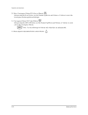
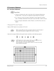
... properly adjusted so that the center of Green, Red, Blue pattern is located.) ✏ Do the convergence adjustments correctly. 4-8 Convergence Adjustment 4-8-1 Convergence Adjustment) Alignment and Adjustments Special Notes ✏ A sensor is attached on the center of each side ...enter the Convergence Mode. Warm up the TV for about five seconds before doing the adjustments. Enter the Convergence Mode by for a least 30 minutes. 2. Samsung Electronics 4-27 Then, redo step 3 to do the convergence adjustments correctly (Especially, perform correct convergence adjustments on ...
... properly adjusted so that the center of Green, Red, Blue pattern is located.) ✏ Do the convergence adjustments correctly. 4-8 Convergence Adjustment 4-8-1 Convergence Adjustment) Alignment and Adjustments Special Notes ✏ A sensor is attached on the center of each side ...enter the Convergence Mode. Warm up the TV for about five seconds before doing the adjustments. Enter the Convergence Mode by for a least 30 minutes. 2. Samsung Electronics 4-27 Then, redo step 3 to do the convergence adjustments correctly (Especially, perform correct convergence adjustments on ...

Service Manual
Page 42
Superimpose the Red and Green colors by pessing the and the keys. 11. select key for B- To adjust BLUE, redo steps 5~7, 13. 14. When the cursor moves vertically 12. If any color is not properly adjusted when displaying the red, blue and green colors, readjust the color. 4-30 Samsung Electronics To adjust RED, redo steps 5~7. Alignment and Adjustments 9. After the green convergence adjustments are completed, press the key to cancel the B-Mute, and (3) the key for R-Mute, (2) the key 13. To superimpose the blue and green colors, press (1) the to save the data. 10.
Superimpose the Red and Green colors by pessing the and the keys. 11. select key for B- To adjust BLUE, redo steps 5~7, 13. 14. When the cursor moves vertically 12. If any color is not properly adjusted when displaying the red, blue and green colors, readjust the color. 4-30 Samsung Electronics To adjust RED, redo steps 5~7. Alignment and Adjustments 9. After the green convergence adjustments are completed, press the key to cancel the B-Mute, and (3) the key for R-Mute, (2) the key 13. To superimpose the blue and green colors, press (1) the to save the data. 10.

Service Manual
Page 43
... cursor. w When any adjustment error happens. Therefore, be sure to correctly adjust during troubleshooting. w When Convergence Adjustment is not normally done or the convergence center is automatically saved and the convergence pattern revets. Samsung Electronics 4-31 w After Factory Auto convergence is saved. The corser moves to center, and then automatically moves up and to perform...
... cursor. w When any adjustment error happens. Therefore, be sure to correctly adjust during troubleshooting. w When Convergence Adjustment is not normally done or the convergence center is automatically saved and the convergence pattern revets. Samsung Electronics 4-31 w After Factory Auto convergence is saved. The corser moves to center, and then automatically moves up and to perform...

Service Manual
Page 44
After the Convergence Adjustments are completde, press the key to correctly adjust during troubeshooting. 4-32 Samsung Electronics DTV Convergence adjustment must be sure to use a screen jig to exit. 3. Therefore, be done same as the above Normal Mode Convergence Adjustment (Use a 16 : 9 screen jig for DTV) When Convergence Adjustment is not normally done or the convergence center is misaligned with the sensing point, any adjustment error happens. Alignment and Adjustments 2.
After the Convergence Adjustments are completde, press the key to correctly adjust during troubeshooting. 4-32 Samsung Electronics DTV Convergence adjustment must be sure to use a screen jig to exit. 3. Therefore, be done same as the above Normal Mode Convergence Adjustment (Use a 16 : 9 screen jig for DTV) When Convergence Adjustment is not normally done or the convergence center is misaligned with the sensing point, any adjustment error happens. Alignment and Adjustments 2.

Service Manual
Page 47
...-G 22 CG-B 23 CG-SYNC 24 D/F 25 GND 26 9[V] 27 GND 28 N.C 29 RXD 30 TXD 31 GND 32 13.5[V] Samsung Electronics Alignment and Adjustments FUNCTION EAST WEST OUT VERTICAL BLANK ABL(Automtic Brightness Limiter) VERTICAL DRIVE (- VOLTAGE) VERTICAL DRIVE (+ VOLTAGE) HORIZONTAL ...SCREEN DISPLAY GREEN IN ON SCREEN DISPLAY RED IN VIDEO SIGNAL MUTE GND SERIAL CLOCK LINE SERIAL DATA LINE HORIZONTAL SYNC VERTICLA OUT GND CONVERGENCE RED CONVERGENCE GREEN CONVERGENCE BLUE CONVERGENCE SYNC DYNAMIC FOCUS GND 9[V] GND N.C RXD TXD GND 13.5[V] VOLT 2.26[V] -12.07[mV] 2.26[V] 3.46[V] 3.53...
...-G 22 CG-B 23 CG-SYNC 24 D/F 25 GND 26 9[V] 27 GND 28 N.C 29 RXD 30 TXD 31 GND 32 13.5[V] Samsung Electronics Alignment and Adjustments FUNCTION EAST WEST OUT VERTICAL BLANK ABL(Automtic Brightness Limiter) VERTICAL DRIVE (- VOLTAGE) VERTICAL DRIVE (+ VOLTAGE) HORIZONTAL ...SCREEN DISPLAY GREEN IN ON SCREEN DISPLAY RED IN VIDEO SIGNAL MUTE GND SERIAL CLOCK LINE SERIAL DATA LINE HORIZONTAL SYNC VERTICLA OUT GND CONVERGENCE RED CONVERGENCE GREEN CONVERGENCE BLUE CONVERGENCE SYNC DYNAMIC FOCUS GND 9[V] GND N.C RXD TXD GND 13.5[V] VOLT 2.26[V] -12.07[mV] 2.26[V] 3.46[V] 3.53...

Service Manual
Page 49
4-9-3 CONVERGENCE MODULE Pins PIN NO ITEM 1 5[V]-CG 2 GND 3 D/F 4 GND 5 SCL1 6 CG-SYNC 7 GND 8 N.C 9 CG-R 10 CG-G 11 CG-B 12 SDA1 13 N.C 14 IR 15 N.C 16 GND ... GH 23 RV 24 RH 25 GND 26 H-BLK 27 V-BLK 28 GND 29 N.C 30 -5[V] 31 5[V] 32 GND Samsung Electronics FUNCTION 5[V]-CG GND DYNAMIC FOCUS GND SERIAL CLOCK LINE 1 CONVERGENCE SYNC GND N.C CONVERGENCE RED CONVERGENCE GREEN CONVERGENCE BLUE SERIAL DATA LINE 1 N.C INPUT REMOCON N.C GND GND GND BULE VERTICAL OUT BULE HORIZONTAL OUT GREEN VERTICAL OUT...
4-9-3 CONVERGENCE MODULE Pins PIN NO ITEM 1 5[V]-CG 2 GND 3 D/F 4 GND 5 SCL1 6 CG-SYNC 7 GND 8 N.C 9 CG-R 10 CG-G 11 CG-B 12 SDA1 13 N.C 14 IR 15 N.C 16 GND ... GH 23 RV 24 RH 25 GND 26 H-BLK 27 V-BLK 28 GND 29 N.C 30 -5[V] 31 5[V] 32 GND Samsung Electronics FUNCTION 5[V]-CG GND DYNAMIC FOCUS GND SERIAL CLOCK LINE 1 CONVERGENCE SYNC GND N.C CONVERGENCE RED CONVERGENCE GREEN CONVERGENCE BLUE SERIAL DATA LINE 1 N.C INPUT REMOCON N.C GND GND GND BULE VERTICAL OUT BULE HORIZONTAL OUT GREEN VERTICAL OUT...
Service Manual
Page 50
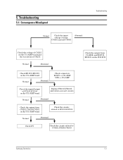
Troubleshooting 5-1 Convergence Misaligned Troubleshooting Nomal Check the input voltage of main CNZ02 and sub CN803 Abnomal Check the voltage of CNZ03 on the CG-AMP board and ... Nomal Abnomal Check DY Check the circuits related to CNZ02,CNZ04,CNZ05 Check the output from CG-MDL and FD855S, FD802S on the SUB PCB Samsung Electronics 5-1 5.
Troubleshooting 5-1 Convergence Misaligned Troubleshooting Nomal Check the input voltage of main CNZ02 and sub CN803 Abnomal Check the voltage of CNZ03 on the CG-AMP board and ... Nomal Abnomal Check DY Check the circuits related to CNZ02,CNZ04,CNZ05 Check the output from CG-MDL and FD855S, FD802S on the SUB PCB Samsung Electronics 5-1 5.
Service Manual
Page 56
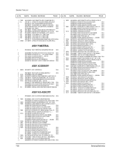
...30mH,2.20mH, S.N.A AA26-30006F TRANS FBT-ANODE CAP ASS'Y;-,FWZ-50A001C, AA27-00249A DEFLECTION YOKE;-,DPD-5292AA,S/S,7,29.1 AA33-00016A MAGNET CONVERGENCE;JH 92LT - 29F,-,29.1M AA39-00018A LEAD CONNECTOR-ASSY;,UL1015#22,UL/CSA,1P AA60-00126B SPACER-CAP;PROJ,EPDM,BLK S.N.A... ..2 BP61-00024E BRACKET-SCREEN,ASSY(BOT);42W5,SECC,T1.0, S.N.A ...3 T0069 AA60-00091J SPACER-FELT;-,FELT,330X10,-,-,BLK,T0.5,- URL : http://itself.sec.samsung.co.kr 7. S.N.A ...3 AA65-00020A CLAMPER CORE-WIRE;55W9,NYLON 66 S.N.A ...3 BP61-00043B HOLDER-SENSOR;W9,PC HB,VIOLET S.N.A ...3 BP61-00052A HOLDER...
...30mH,2.20mH, S.N.A AA26-30006F TRANS FBT-ANODE CAP ASS'Y;-,FWZ-50A001C, AA27-00249A DEFLECTION YOKE;-,DPD-5292AA,S/S,7,29.1 AA33-00016A MAGNET CONVERGENCE;JH 92LT - 29F,-,29.1M AA39-00018A LEAD CONNECTOR-ASSY;,UL1015#22,UL/CSA,1P AA60-00126B SPACER-CAP;PROJ,EPDM,BLK S.N.A... ..2 BP61-00024E BRACKET-SCREEN,ASSY(BOT);42W5,SECC,T1.0, S.N.A ...3 T0069 AA60-00091J SPACER-FELT;-,FELT,330X10,-,-,BLK,T0.5,- URL : http://itself.sec.samsung.co.kr 7. S.N.A ...3 AA65-00020A CLAMPER CORE-WIRE;55W9,NYLON 66 S.N.A ...3 BP61-00043B HOLDER-SENSOR;W9,PC HB,VIOLET S.N.A ...3 BP61-00052A HOLDER...
Service Manual
Page 57
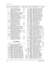
... T0121 3301-001201 CORE-FERRITE;AE,21x11x32mm,1500,280G ...3 T0079 AA33-00017A MAGNET CONVERGENCE;JH 92LT - 29G,-,29.1M ...3 T0081 6003-001023 SCREW-TAPTITE;RWH,+,B,M3,... T431 AA26-50001U TRANS-HORIZ.DRIVE;-,-,-,28mH,-,-,105uH,- ...3 T461 AA26-50001V TRANS-HORIZ.DRIVE;-,-,-,6.0mH,-,-,113uH, ...3 LR401S AA27-30003M COIL LINEARITY;-,5uH,OWA14x15,USRC0.1x60 7-2 Samsung Electronics Description ; Specification Remark ....4 ....4 ...3 ...3 ...3 ..2 T0027 ...3 ...3 T0117 ...3 T0078 ...3 T0076 ...3 ...3 ...3 ...3 T0081 ...3 ...3 ...3 ...3 T0114 ...3 T0109 ...3 T0051 ...3 T0107 ....4 T0072 ...
... T0121 3301-001201 CORE-FERRITE;AE,21x11x32mm,1500,280G ...3 T0079 AA33-00017A MAGNET CONVERGENCE;JH 92LT - 29G,-,29.1M ...3 T0081 6003-001023 SCREW-TAPTITE;RWH,+,B,M3,... T431 AA26-50001U TRANS-HORIZ.DRIVE;-,-,-,28mH,-,-,105uH,- ...3 T461 AA26-50001V TRANS-HORIZ.DRIVE;-,-,-,6.0mH,-,-,113uH, ...3 LR401S AA27-30003M COIL LINEARITY;-,5uH,OWA14x15,USRC0.1x60 7-2 Samsung Electronics Description ; Specification Remark ....4 ....4 ...3 ...3 ...3 ..2 T0027 ...3 ...3 T0117 ...3 T0078 ...3 T0076 ...3 ...3 ...3 ...3 T0081 ...3 ...3 ...3 ...3 T0114 ...3 T0109 ...3 T0051 ...3 T0107 ....4 T0072 ...

Service Manual
Page 67
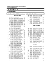
........5 T0119 AA09-00032A IC MICOM;,TSC87251G2D-OTP,4.5 TO 5.5V,-, S.N.A .....5 1 AA41-00717D PCB (FR 4) 4L(AU);CONVERGENCE,FR-4,4,1.6 S.N.A .....5 IC125 BP13-00003A IC ASIC;SDC12,128,-0.3 TO +3.8,0 TO 70,Q .....5 0202-001167 SOLDER-CREAM;RX3603-2330HO...AA,TP,6.5x2.5 ....4 R024 2004-001970 R-METAL(S);1.8Kohm,1%,1/2W,AA,TP,6.5x2.5 ....4 R024 2004-001970 R-METAL(S);1.8Kohm,1%,1/2W,AA,TP,6.5x2.5 7-12 Samsung Electronics Electrical Parts List Loc. Specification Remark .....5 C120 .....5 C120 .....5 C120 .....5 C120 .....5 C120 .....5 C120 .....5 C120 .....5 C120 .....5 C120 .....5 ...
........5 T0119 AA09-00032A IC MICOM;,TSC87251G2D-OTP,4.5 TO 5.5V,-, S.N.A .....5 1 AA41-00717D PCB (FR 4) 4L(AU);CONVERGENCE,FR-4,4,1.6 S.N.A .....5 IC125 BP13-00003A IC ASIC;SDC12,128,-0.3 TO +3.8,0 TO 70,Q .....5 0202-001167 SOLDER-CREAM;RX3603-2330HO...AA,TP,6.5x2.5 ....4 R024 2004-001970 R-METAL(S);1.8Kohm,1%,1/2W,AA,TP,6.5x2.5 ....4 R024 2004-001970 R-METAL(S);1.8Kohm,1%,1/2W,AA,TP,6.5x2.5 7-12 Samsung Electronics Electrical Parts List Loc. Specification Remark .....5 C120 .....5 C120 .....5 C120 .....5 C120 .....5 C120 .....5 C120 .....5 C120 .....5 C120 .....5 C120 .....5 ...

Service Manual
Page 85
....9MM, 3301-001324 CORE-FERRITE BEAD;AB,15OHM,2X1.25X0.9MM, AA09-00032A IC MICOM;,TSC87251G2D-OTP,4.5 TO 5.5V,-, S.N.A AA41-00717D PCB (FR 4) 4L(AU);CONVERGENCE,FR-4,4,1.6 S.N.A BP13-00003A IC ASIC;SDC12,128,-0.3 TO +3.8,0 TO 70,Q 0202-001167 SOLDER-CREAM;RX3603-2330HO,S45A,PASTE,SNS.N.A BP96-00020G ASSY HEAT SINK P;AA62...,5%,63V,TP,7.5x4.0x5.0m 2305-000665 C-FILM,MPEF;100nF,5%,63V,TP,7.5x4.0x5.0m 2401-000025 C-AL;100uF,20%,16V,GP,TP,6.3x11,5 7-30 Samsung Electronics Loc. Electrical Parts List Loc. No.
....9MM, 3301-001324 CORE-FERRITE BEAD;AB,15OHM,2X1.25X0.9MM, AA09-00032A IC MICOM;,TSC87251G2D-OTP,4.5 TO 5.5V,-, S.N.A AA41-00717D PCB (FR 4) 4L(AU);CONVERGENCE,FR-4,4,1.6 S.N.A BP13-00003A IC ASIC;SDC12,128,-0.3 TO +3.8,0 TO 70,Q 0202-001167 SOLDER-CREAM;RX3603-2330HO,S45A,PASTE,SNS.N.A BP96-00020G ASSY HEAT SINK P;AA62...,5%,63V,TP,7.5x4.0x5.0m 2305-000665 C-FILM,MPEF;100nF,5%,63V,TP,7.5x4.0x5.0m 2401-000025 C-AL;100uF,20%,16V,GP,TP,6.3x11,5 7-30 Samsung Electronics Loc. Electrical Parts List Loc. No.

Service Manual
Page 91
... S.N.A ...3 RZ120 2008-001097 R-FUSIBLE(S);33OHM,5%,1/2W,AC,BK,2.5X6.5 ...3 T0121 3301-001201 CORE-FERRITE;AE,21x11x32mm,1500,280G ...3 T0079 AA33-00017A MAGNET CONVERGENCE;JH 92LT - 29G,-,29.1M ...3 T0076 AA39-20055C LEAD CONNECTOR-ASSY;,6P,500,YBNH025-06,6 ...3 QZ102 AA96-00243L ASSY H/S;-,CRT,AA62-000450A,2SC2344,... ...3 BP97-00166A ASSY SMD;HCM4215WJX/XAA,DVI-AUTO,P55A S.N.A ....4 DD512 0401-000133 DIODE-SWITCHING;RLS4148,100V,200MA,SOD-8 7-36 Samsung Electronics Electrical Parts List Loc. Specification Remark Loc. Code No. Code No. No. Description ; Description ;
... S.N.A ...3 RZ120 2008-001097 R-FUSIBLE(S);33OHM,5%,1/2W,AC,BK,2.5X6.5 ...3 T0121 3301-001201 CORE-FERRITE;AE,21x11x32mm,1500,280G ...3 T0079 AA33-00017A MAGNET CONVERGENCE;JH 92LT - 29G,-,29.1M ...3 T0076 AA39-20055C LEAD CONNECTOR-ASSY;,6P,500,YBNH025-06,6 ...3 QZ102 AA96-00243L ASSY H/S;-,CRT,AA62-000450A,2SC2344,... ...3 BP97-00166A ASSY SMD;HCM4215WJX/XAA,DVI-AUTO,P55A S.N.A ....4 DD512 0401-000133 DIODE-SWITCHING;RLS4148,100V,200MA,SOD-8 7-36 Samsung Electronics Electrical Parts List Loc. Specification Remark Loc. Code No. Code No. No. Description ; Description ;
Service Manual
Page 93
... T0078 ...3 T0117 ..2 T0261 ...3 BP98-00084A ASSY K/D-CRT-R;HCM4215W3S/XAA AA03-00200A CRT MONO;P16LSG03RJA,FREE,3.30mH,2.20mH, S.N.A AA33-00016A MAGNET CONVERGENCE;JH 92LT - 29F,-,29.1M AA39-00018A LEAD CONNECTOR-ASSY;,UL1015#22,UL/CSA,1P AA60-00126B SPACER-CAP;PROJ,EPDM,BLK S.N.A AA60-...;,PJTV,T0.5,NYLON66 V2 S.N.A AA27-00249A DEFLECTION YOKE;-,DPD-5292AA,S/S,7,29.1 AA26-30006F TRANS FBT-ANODE CAP ASS'Y;-,FWZ-50A001C, 7-38 Samsung Electronics Specification Remark Loc. Specification Remark ...3 T0076 ...3 PL1 ..2 ...3 ...3 ...3 ....4 Q01 ....4 PCB ....4 D01 ....4 R01 ....4 R02...
... T0078 ...3 T0117 ..2 T0261 ...3 BP98-00084A ASSY K/D-CRT-R;HCM4215W3S/XAA AA03-00200A CRT MONO;P16LSG03RJA,FREE,3.30mH,2.20mH, S.N.A AA33-00016A MAGNET CONVERGENCE;JH 92LT - 29F,-,29.1M AA39-00018A LEAD CONNECTOR-ASSY;,UL1015#22,UL/CSA,1P AA60-00126B SPACER-CAP;PROJ,EPDM,BLK S.N.A AA60-...;,PJTV,T0.5,NYLON66 V2 S.N.A AA27-00249A DEFLECTION YOKE;-,DPD-5292AA,S/S,7,29.1 AA26-30006F TRANS FBT-ANODE CAP ASS'Y;-,FWZ-50A001C, 7-38 Samsung Electronics Specification Remark Loc. Specification Remark ...3 T0076 ...3 PL1 ..2 ...3 ...3 ...3 ....4 Q01 ....4 PCB ....4 D01 ....4 R01 ....4 R02...


