

Service Manual
Page 2
... restore all exposed metal parts, including: antennas, handle brackets, metal cabinets, screwheads and control shafts. Carefully reinstall the picture tube shields and mounting hardware; these safety, servicing and ESD precautions to the customer. 4. Samsung Electronics 1-1 When reinstalling the chassis and its assemblies, be corrected before the unit is done on the service data schematic. Antenna Cold Check: With the unit's AC...
... restore all exposed metal parts, including: antennas, handle brackets, metal cabinets, screwheads and control shafts. Carefully reinstall the picture tube shields and mounting hardware; these safety, servicing and ESD precautions to the customer. 4. Samsung Electronics 1-1 When reinstalling the chassis and its assemblies, be corrected before the unit is done on the service data schematic. Antenna Cold Check: With the unit's AC...

Service Manual
Page 3
... handle the picture tube by close-tolerance, safety-related components and adjustments. These safety features and the protection they give might create a safety hazard. Use replacement components that the replacement picture tube is inserted correctly, do the following areas: Antenna wiring, sharp edges, and especially the AC and high voltage power supplies. A replacement part that does not have a secondary ground system in -line" picture tubes are otherwise damaged...
... handle the picture tube by close-tolerance, safety-related components and adjustments. These safety features and the protection they give might create a safety hazard. Use replacement components that the replacement picture tube is inserted correctly, do the following areas: Antenna wiring, sharp edges, and especially the AC and high voltage power supplies. A replacement part that does not have a secondary ground system in -line" picture tubes are otherwise damaged...
Service Manual
Page 4
... to : (a) Remove or reinstall any of the AC plug and accessible conductive parts (see above the printed circuit board for safety. Always unplug the unit's AC power cord from the AC source and turn the power switch ON. Check the insulation between each blade of the B+ voltage interlocks. If some parts inside the optical engine (except lamp) are damaged, replace the whole optical engine. After servicing, always check that the...
... to : (a) Remove or reinstall any of the AC plug and accessible conductive parts (see above the printed circuit board for safety. Always unplug the unit's AC power cord from the AC source and turn the power switch ON. Check the insulation between each blade of the B+ voltage interlocks. If some parts inside the optical engine (except lamp) are damaged, replace the whole optical engine. After servicing, always check that the...
Service Manual
Page 5
...will be installed. 9. Use only a grounded-tip soldering iron when soldering or unsoldering ESDs. 6. Immediately before handling any servicing other conductive materials. 8. To reduce the risk of electric shock do so. 1-4 Samsung Electronics ...power- Minimize body motions when handling unpackaged replacement ESDs. Do not use by conductive foam, aluminum foil or other than that damage ESDs. 5. Many solder removal devices are electrically shorted together by qualified service personnel only. These can generate electrical charges that contained in the operating instructions...
...will be installed. 9. Use only a grounded-tip soldering iron when soldering or unsoldering ESDs. 6. Immediately before handling any servicing other conductive materials. 8. To reduce the risk of electric shock do so. 1-4 Samsung Electronics ...power- Minimize body motions when handling unpackaged replacement ESDs. Do not use by conductive foam, aluminum foil or other than that damage ESDs. 5. Many solder removal devices are electrically shorted together by qualified service personnel only. These can generate electrical charges that contained in the operating instructions...

Service Manual
Page 7
...-Tr Multi-channel Television Sound National Association of Broadcasters National Electric Code National Television Systems Committee On Screen Display Printed Circuit Board Phase-Locked Loop Pulse Width Modulation Quadrature Intermediate Frequency Right Resistor & Capacitor Radio Frequency Red-Y Second Audio Program Surface Acoustic Wave(Filter) Sound Intermediate Frequency Switching Mode Power Supply Signal/Noise Switch Test Point Transistor Transistor Logic Television Ultra High Frequency Underwriters Laboratories Ultraviolet Variable-Capacitance Diode Voltage Controlled Oscillator Voltage...
...-Tr Multi-channel Television Sound National Association of Broadcasters National Electric Code National Television Systems Committee On Screen Display Printed Circuit Board Phase-Locked Loop Pulse Width Modulation Quadrature Intermediate Frequency Right Resistor & Capacitor Radio Frequency Red-Y Second Audio Program Surface Acoustic Wave(Filter) Sound Intermediate Frequency Switching Mode Power Supply Signal/Noise Switch Test Point Transistor Transistor Logic Television Ultra High Frequency Underwriters Laboratories Ultraviolet Variable-Capacitance Diode Voltage Controlled Oscillator Voltage...
Service Manual
Page 13
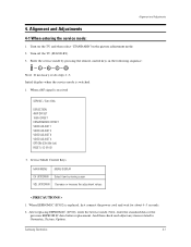
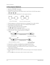
... service mode: 1. Turn on the TV, and then select "STANDARD"on the picture adjustment mode. 2. Samsung Electronics 4-1 Alignment and Adjustments 4. Enter the service mode by moving cursor VOL UP/DOWN Decrease or increase the adjustment values < PRECAUTIONS > 1. When a RF signal is replaced, first connect the power cord and wait for about 4~5 seconds. 2. Initial display when the service mode is switched. 1. And then check and adjust any items related to Geometric, Picture, Option. Turn off the TV (STAND...
... service mode: 1. Turn on the TV, and then select "STANDARD"on the picture adjustment mode. 2. Samsung Electronics 4-1 Alignment and Adjustments 4. Enter the service mode by moving cursor VOL UP/DOWN Decrease or increase the adjustment values < PRECAUTIONS > 1. When a RF signal is replaced, first connect the power cord and wait for about 4~5 seconds. 2. Initial display when the service mode is switched. 1. And then check and adjust any items related to Geometric, Picture, Option. Turn off the TV (STAND...

Service Manual
Page 24
... screen. 10. Input a sub-brightness adjustment signal. (TOSHIBA PATTERN) 2. Warm up the TV for at least 30 minutes. 5. Adjust RR471S (located on the deflection board). 2. Alignment and Adjustments 4-4 Other Adjustments 4-4-1 Screen Adjustment 1. Turn to RK,GK,BK. 5. Warm up the TV for at least 10 minutes. 4. Adjust the low light with viewing the light side of each flyback line.) 4-4-2 White Balance Adjustment 1. Press the Menu key to exit. 4-4-4 High Voltage (29KV) Check PRECAUTION 1. In the stand...
... screen. 10. Input a sub-brightness adjustment signal. (TOSHIBA PATTERN) 2. Warm up the TV for at least 30 minutes. 5. Adjust RR471S (located on the deflection board). 2. Alignment and Adjustments 4-4 Other Adjustments 4-4-1 Screen Adjustment 1. Turn to RK,GK,BK. 5. Warm up the TV for at least 10 minutes. 4. Adjust the low light with viewing the light side of each flyback line.) 4-4-2 White Balance Adjustment 1. Press the Menu key to exit. 4-4-4 High Voltage (29KV) Check PRECAUTION 1. In the stand...
Service Manual
Page 25
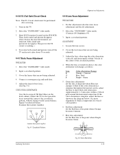
... that are removed, both sound and picture, turn off the TV and reset it after about 30 seconds. 4-4-7 Static Focus Adjustment PRECAUTION 1. Green 5. Alignment and Adjustments 4-4-8 Lens Focus Adjustment PRECAUTIONS 1. If the color aberration is working. ) 4. circuit is irregular throughout the picture screen, adjust the lens to Red. Connect a convergence jig and read data. 5. Input a crosshatch pattern. 3. Red Purple - Crimson Blue - Green lens adjustment: Set the lens at the point where Blue just changes to show Red color aberration (approximately...
... that are removed, both sound and picture, turn off the TV and reset it after about 30 seconds. 4-4-7 Static Focus Adjustment PRECAUTION 1. Green 5. Alignment and Adjustments 4-4-8 Lens Focus Adjustment PRECAUTIONS 1. If the color aberration is working. ) 4. circuit is irregular throughout the picture screen, adjust the lens to Red. Connect a convergence jig and read data. 5. Input a crosshatch pattern. 3. Red Purple - Crimson Blue - Green lens adjustment: Set the lens at the point where Blue just changes to show Red color aberration (approximately...
Service Manual
Page 26
..." video mode. 2. Warm up the set at the point where the focus is misaligned (Use an audio oscillator). 6. Press the button on the remote control to return to the Convergence Adjustment mode. 16. Adjust G-Focus so that the surrounding flash can be omitted because the variance of VM (When VM 2-Pole Adjustment is mounted.) 14. Press the button on the remote control.) 9. Adjust the Focus-pack VR for fine focusing. 15. G-FOCUS G-FOCUS CORE...
..." video mode. 2. Warm up the set at the point where the focus is misaligned (Use an audio oscillator). 6. Press the button on the remote control to return to the Convergence Adjustment mode. 16. Adjust G-Focus so that the surrounding flash can be omitted because the variance of VM (When VM 2-Pole Adjustment is mounted.) 14. Press the button on the remote control.) 9. Adjust the Focus-pack VR for fine focusing. 15. G-FOCUS G-FOCUS CORE...

Service Manual
Page 27
... to keep beam linearity and uniformity in size. The input AFC signal is about 2.25V), TL431 turns ON, the base port of Q481(Tr KSC815-Y), D479, D478, and C492. When QR401S turns ON, high voltage is determined by performing sync lock every 1H line, and detecting beam fluctuation at 1H line, and then controlling the IC current of Dead Time is +27V. High...
... to keep beam linearity and uniformity in size. The input AFC signal is about 2.25V), TL431 turns ON, the base port of Q481(Tr KSC815-Y), D479, D478, and C492. When QR401S turns ON, high voltage is determined by performing sync lock every 1H line, and detecting beam fluctuation at 1H line, and then controlling the IC current of Dead Time is +27V. High...
Service Manual
Page 37
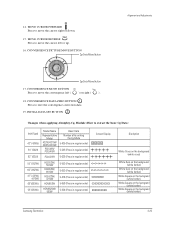
... (white border) White Oval on the background (white border) White Square on the backgrand (white border ) White Square on the backgrand (white border ) White Square on the backgrand (white border ) Samsung Electronics 4-25 MOVE CURSOR FORWARD Press to zero the convergence correction data. 19. CONVERGENCE DATA ZERO BUTTON Press to move the convergence left or up. 16. CONVERGENCE PICTURE MOVE BUTTON Alignment and Adjustments 17. 14. INITIAL DATA SET BUTTON Changes...
... (white border) White Oval on the background (white border) White Square on the backgrand (white border ) White Square on the backgrand (white border ) White Square on the backgrand (white border ) Samsung Electronics 4-25 MOVE CURSOR FORWARD Press to zero the convergence correction data. 19. CONVERGENCE DATA ZERO BUTTON Press to move the convergence left or up. 16. CONVERGENCE PICTURE MOVE BUTTON Alignment and Adjustments 17. 14. INITIAL DATA SET BUTTON Changes...

Owners Instructions
Page 4
... qualified service personnei. This television receiver provides display of television closed captioning in accordance with part 15 of overhead power lines or other controls may result in the vich]ity of the FCC Rules. Unauthorized substitutions may cause undesired operation. This device complies with 15.119 of antenna discharge unit, connection to grounding electrodes, and requirements for long periods of any service or repairs to this TV...
... qualified service personnei. This television receiver provides display of television closed captioning in accordance with part 15 of overhead power lines or other controls may result in the vich]ity of the FCC Rules. Unauthorized substitutions may cause undesired operation. This device complies with 15.119 of antenna discharge unit, connection to grounding electrodes, and requirements for long periods of any service or repairs to this TV...
Owners Instructions
Page 6
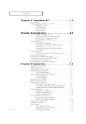
... Set Top Box (480p, 10800 Connecting Surzound Speakers Installing Battezies in the Remote Control 3: Operation Turning tile TV On and Off Plug & Play Featuze Using the PezfVct Focus Feature Adjusting Manual convergence Adjust Red Convergence Viewing the Menus and On Sczeen Displays Viewing the Menus Viewing the Display Selecting a Menu Language Selecting the Antenna Input Memozizing the Channels Selecting the Video Signal source StoIing Channels in Memozy (Automatic Method) ....... 1 (ION] EN] S CONTENTS ] Chapter Chapter Chapter 1: Your New TV List...
... Set Top Box (480p, 10800 Connecting Surzound Speakers Installing Battezies in the Remote Control 3: Operation Turning tile TV On and Off Plug & Play Featuze Using the PezfVct Focus Feature Adjusting Manual convergence Adjust Red Convergence Viewing the Menus and On Sczeen Displays Viewing the Menus Viewing the Display Selecting a Menu Language Selecting the Antenna Input Memozizing the Channels Selecting the Video Signal source StoIing Channels in Memozy (Automatic Method) ....... 1 (ION] EN] S CONTENTS ] Chapter Chapter Chapter 1: Your New TV List...

Owners Instructions
Page 7
... Up Your Remote Control to Automatically Set the TV Clock 3.20 Selecting a Signal Source (External A 3.21 4: Special Features ............ 4.1 Fine Tuning Channels 4.1 Digital Noise Reduction 4.2 Changing the Screen Size 4.3 Using the R.surf Feature 4.4 Setting the On/Off Timer 4.5 Setting the Sleep Timer 4.(5 Dolby Surround 4.7 Choosing a Multi Channel Sound (MTS) track 4.8 Auto Vutume 4.9 Viewing Closed Captions 4. CONTENTS Chapter Chapter Chapter Appendix 3: Operation (Cont.) Sound Control .......... 3.14 3.16 Adjusting the Vulume...
... Up Your Remote Control to Automatically Set the TV Clock 3.20 Selecting a Signal Source (External A 3.21 4: Special Features ............ 4.1 Fine Tuning Channels 4.1 Digital Noise Reduction 4.2 Changing the Screen Size 4.3 Using the R.surf Feature 4.4 Setting the On/Off Timer 4.5 Setting the Sleep Timer 4.(5 Dolby Surround 4.7 Choosing a Multi Channel Sound (MTS) track 4.8 Auto Vutume 4.9 Viewing Closed Captions 4. CONTENTS Chapter Chapter Chapter Appendix 3: Operation (Cont.) Sound Control .......... 3.14 3.16 Adjusting the Vulume...

Owners Instructions
Page 12
... optimum picture set in the Factory. For example, to operate your VCR and cable box. O Menu Displays the main on -screen menu items and change menu values. O Caption Controlsthe captiondecoder. @ PIP Activatespicturein picture, e Perfect Focus Press to adjust for details. CH (Favorite Channel) Pressto switchbetweenyour favoritechannels. 1.5 ( ..,,p. _o :Y)tl/ N_ rv Aspect Press to change the screen size. O I1_ Surround (For model PCL545R) Selects one of Phantom modes (Off, Normal, Phantom or Wide), O MTS (Multichannel Television...
... optimum picture set in the Factory. For example, to operate your VCR and cable box. O Menu Displays the main on -screen menu items and change menu values. O Caption Controlsthe captiondecoder. @ PIP Activatespicturein picture, e Perfect Focus Press to adjust for details. CH (Favorite Channel) Pressto switchbetweenyour favoritechannels. 1.5 ( ..,,p. _o :Y)tl/ N_ rv Aspect Press to change the screen size. O I1_ Surround (For model PCL545R) Selects one of Phantom modes (Off, Normal, Phantom or Wide), O MTS (Multichannel Television...

Owners Instructions
Page 19
...[O cable COIIIIpC[ ou[ using a VCR. (Also see "Selecting a Signal Source (External A/V)" on [)age 3.21) 1 Locate the A/V outputjacKs on me camcorder, They are usua_q found 3n the side or rear of the camcoraer, "i3/Front Panel 2 Connect an audio cable between the VIDEO OUTPUTjack on the camcorder and the VIDEOterminm on the front of its picture and sound to Record from the TV Your TV can...
...[O cable COIIIIpC[ ou[ using a VCR. (Also see "Selecting a Signal Source (External A/V)" on [)age 3.21) 1 Locate the A/V outputjacKs on me camcorder, They are usua_q found 3n the side or rear of the camcoraer, "i3/Front Panel 2 Connect an audio cable between the VIDEO OUTPUTjack on the camcorder and the VIDEOterminm on the front of its picture and sound to Record from the TV Your TV can...

Owners Instructions
Page 20
... the TV. Connect a set of audio cabies between the DVD audio injacks on the TV and the AUDtO OUTjabkS on the DVD ptayer, TVRe= Panel Toenable Component video viewing, connect video cables between the Y, PB, and Pk inputs on the TV and Y,P_,and P_ (or Y,C_,C,_)outputs on the DVD player, DVDPlayer Connecting audio and video jacks Connect a set of aumo caoies Between the AUDIO IN jacks on the TV and the AUDIO OUTjacks on the DVD player. 2 Connect video cables...
... the TV. Connect a set of audio cabies between the DVD audio injacks on the TV and the AUDtO OUTjabkS on the DVD ptayer, TVRe= Panel Toenable Component video viewing, connect video cables between the Y, PB, and Pk inputs on the TV and Y,P_,and P_ (or Y,C_,C,_)outputs on the DVD player, DVDPlayer Connecting audio and video jacks Connect a set of aumo caoies Between the AUDIO IN jacks on the TV and the AUDIO OUTjacks on the DVD player. 2 Connect video cables...

Owners Instructions
Page 21
... Y,Ps.and P_ (or Y.CB.C,)outputs on the DTVSet:top box_ 2 To enable Component video viewing. Note: I ,\P] 2.8 l _( / ]NSIAI AlL /N INSTALLATION ] Connecting a DTV Set-Top Box (480p, 1080i) When switching to the DTV mode, either dS0p oi- 1080i according to your amp Speakers "IVRealPanel SunoundAmp. Surround_eaksrA _lr_l_d,_B CentsrSpealmr (} I ?or an explanation of the _f Then connect me surrouna soeakers to the input signal.
... Y,Ps.and P_ (or Y.CB.C,)outputs on the DTVSet:top box_ 2 To enable Component video viewing. Note: I ,\P] 2.8 l _( / ]NSIAI AlL /N INSTALLATION ] Connecting a DTV Set-Top Box (480p, 1080i) When switching to the DTV mode, either dS0p oi- 1080i according to your amp Speakers "IVRealPanel SunoundAmp. Surround_eaksrA _lr_l_d,_B CentsrSpealmr (} I ?or an explanation of the _f Then connect me surrouna soeakers to the input signal.

Owners Instructions
Page 37
... the standard factory settings. Choose Custom if you can select "Custom" which automatically recalls your personalized picture settings. 1 Press the Menu button, PICTUREicon witt be highlighted (blinking). Yuu carl activate either Standard, Dynamic or Mild by pressing EMode (or by making a selection from the menu). Or, you want to at the factory. Choose Mild ("Mild Contrast") when viewing the TV in the...
... the standard factory settings. Choose Custom if you can select "Custom" which automatically recalls your personalized picture settings. 1 Press the Menu button, PICTUREicon witt be highlighted (blinking). Yuu carl activate either Standard, Dynamic or Mild by pressing EMode (or by making a selection from the menu). Or, you want to at the factory. Choose Mild ("Mild Contrast") when viewing the TV in the...
Owners Instructions
Page 66
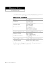
... "TV" mode. Adjust the antenna. Check the antenna connections. Adjustthepicture settings. Unplug the TV for a long time, images may be burned onto the screen. 5.1 ( }{AP] i i VE ]}/( [IB] ISI I()O]/NG Note: If you watch a still image or the screen in . If none of possible problems and solutions. Make sure the program is working. Poor sound qualit3< No picture or sound. Press the "MODE" button to have a problem, first try operating it again. Picture roils vertically. Try another channel...
... "TV" mode. Adjust the antenna. Check the antenna connections. Adjustthepicture settings. Unplug the TV for a long time, images may be burned onto the screen. 5.1 ( }{AP] i i VE ]}/( [IB] ISI I()O]/NG Note: If you watch a still image or the screen in . If none of possible problems and solutions. Make sure the program is working. Poor sound qualit3< No picture or sound. Press the "MODE" button to have a problem, first try operating it again. Picture roils vertically. Try another channel...


