Operation Manual
Page 3
... Keep cord from receptacle. Do not reach underneath work area well lit. KEEP CHILDREN AND VISITORS AWAY. Do not use of parts, mounting and any tool. USE RECOMMENDED ACCESSORIES. All visitors should wear safety glasses and be properly repaired or replaced by removing ...POWER TOOL. Be sure switch is moving. BLADE COASTS AFTER BEING TURNED OFF. 3 - Don't use and reduce the risk of moving parts. Do not wear loose clothing, gloves, neckties, or jewelry. Sharp blades minimize stalling and kickback. KEEP HANDS AWAY FROM CUTTING AREA. ...
... Keep cord from receptacle. Do not reach underneath work area well lit. KEEP CHILDREN AND VISITORS AWAY. Do not use of parts, mounting and any tool. USE RECOMMENDED ACCESSORIES. All visitors should wear safety glasses and be properly repaired or replaced by removing ...POWER TOOL. Be sure switch is moving. BLADE COASTS AFTER BEING TURNED OFF. 3 - Don't use and reduce the risk of moving parts. Do not wear loose clothing, gloves, neckties, or jewelry. Sharp blades minimize stalling and kickback. KEEP HANDS AWAY FROM CUTTING AREA. ...
Operation Manual
Page 4
... kickback, always support large panels. REMOVE ALL FENCES AND AUXILIARY TABLES before cutting. NEVER TOUCH BLADE or other parts may cause the risk of the electric cord or plug is driven back towards the operator. A push stick is the equipment-grounding ...conductor. When ripping narrow stock, always use only identical replacement parts. Always use brake fluids, gasoline, petroleum-based products, or any other moving parts during use. NEVER START A TOOL WHEN ANY ROTATING COMPONENT IS IN CONTACT WITH THE WORKPIECE...
... kickback, always support large panels. REMOVE ALL FENCES AND AUXILIARY TABLES before cutting. NEVER TOUCH BLADE or other parts may cause the risk of the electric cord or plug is driven back towards the operator. A push stick is the equipment-grounding ...conductor. When ripping narrow stock, always use only identical replacement parts. Always use brake fluids, gasoline, petroleum-based products, or any other moving parts during use. NEVER START A TOOL WHEN ANY ROTATING COMPONENT IS IN CONTACT WITH THE WORKPIECE...
Operation Manual
Page 5
... of accessories are specially designed to filter out microscopic particles. 5 - h) Never operate saw blade. To reduce your exposure, work . NEVER stand or have any part of your body in place and operating. d) Not releasing the work thrown back toward you) by power sanding, sawing, grinding, drilling, and other construction activities...
... of accessories are specially designed to filter out microscopic particles. 5 - h) Never operate saw blade. To reduce your exposure, work . NEVER stand or have any part of your body in place and operating. d) Not releasing the work thrown back toward you) by power sanding, sawing, grinding, drilling, and other construction activities...
Operation Manual
Page 8
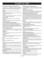
... the workpiece into two pieces. The blades or knives remove material from the cutterhead. Gum A sticky, sap-based residue from a block so the end (or part of cut will not cut made at 90°. As it securely against the table or fence during a ripping operation. Worktable Surface where the workpiece...
... the workpiece into two pieces. The blades or knives remove material from the cutterhead. Gum A sticky, sap-based residue from a block so the end (or part of cut will not cut made at 90°. As it securely against the table or fence during a ripping operation. Worktable Surface where the workpiece...
Operation Manual
Page 13
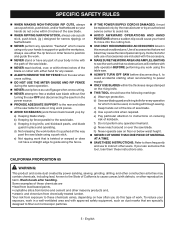
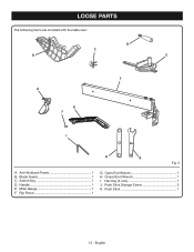
Rip Fence 1 G. Hex Key (5 mm 1 J. English Blade Guard 1 C. Closed End Wrench 1 I H G Fig. 5 A. Push Stick 1 13 - Anti-Kickback Pawls 1 B. Switch Key 1 D. Miter Gauge 1 F. LOOSE PARTS The following items are included with the table saw: D C B E F A K J I . Handle 1 E. Open End Wrench 1 H. Push Stick Storage Screw 2 K.
Rip Fence 1 G. Hex Key (5 mm 1 J. English Blade Guard 1 C. Closed End Wrench 1 I H G Fig. 5 A. Push Stick 1 13 - Anti-Kickback Pawls 1 B. Switch Key 1 D. Miter Gauge 1 F. LOOSE PARTS The following items are included with the table saw: D C B E F A K J I . Handle 1 E. Open End Wrench 1 H. Push Stick Storage Screw 2 K.
Operation Manual
Page 14
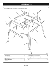
Lower Side Brace 2 C. LOOSE PARTS The following items are included with the table saw leg stand: I C D C D E F B A H I E G I E A B H I . Upper Brace 2 D. Leg 4 14 - English Hex Nut 20 H Fig. 6 F. Carriage Bolt (1/4 - 20 x 1/2 in 4 H Foot 4 I H F A. Carriage Bolt (1/4 - 20 x 1-3/8 in 16 G. Lower Brace 2 B. Upper Side Brace 2 E.
Lower Side Brace 2 C. LOOSE PARTS The following items are included with the table saw leg stand: I C D C D E F B A H I E G I E A B H I . Upper Brace 2 D. Leg 4 14 - English Hex Nut 20 H Fig. 6 F. Carriage Bolt (1/4 - 20 x 1/2 in 4 H Foot 4 I H F A. Carriage Bolt (1/4 - 20 x 1-3/8 in 16 G. Lower Brace 2 B. Upper Side Brace 2 E.
Operation Manual
Page 15
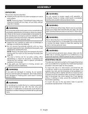
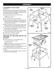
... injury. Failure to accommodate the saw base, lock washers, hex nuts, and the thickness of this section. 15 - Tighten all loose parts, and satisfactorily operated the tool. English WARNING: Do not use bolts that may have been improperly assembled could result in serious personal injury.... workbench or other mounting surface. Ignoring these precautions can occur during shipping. Do not discard the packing material until the parts are damaged or missing, do not operate this warning can result in serious personal injury. Four bolt holes have carefully inspected the ...
... injury. Failure to accommodate the saw base, lock washers, hex nuts, and the thickness of this section. 15 - Tighten all loose parts, and satisfactorily operated the tool. English WARNING: Do not use bolts that may have been improperly assembled could result in serious personal injury.... workbench or other mounting surface. Ignoring these precautions can occur during shipping. Do not discard the packing material until the parts are damaged or missing, do not operate this warning can result in serious personal injury. Four bolt holes have carefully inspected the ...
Operation Manual
Page 16
... the leg set to the bottom of the legs, with the legs wide end up. (Upper braces have obtained the missing part(s). Take the following from loose parts. Place an upper brace inside two of each end.) Make sure the dimples on the leg align with hardware for... hardware securely with the socket wrench. Tighten all hex nuts securely with the socket wrench. Install a foot to desired location. If any part, refer to install the lower braces. UPPER BRACE CARRIAGE BOLT HEX NUT UPPER SIDE BRACE LOWER SIDE BRACE HEX NUT FOOT LEG LOWER BRACE CARRIAGE...
... the leg set to the bottom of the legs, with the legs wide end up. (Upper braces have obtained the missing part(s). Take the following from loose parts. Place an upper brace inside two of each end.) Make sure the dimples on the leg align with hardware for... hardware securely with the socket wrench. Tighten all hex nuts securely with the socket wrench. Install a foot to desired location. If any part, refer to install the lower braces. UPPER BRACE CARRIAGE BOLT HEX NUT UPPER SIDE BRACE LOWER SIDE BRACE HEX NUT FOOT LEG LOWER BRACE CARRIAGE...
Operation Manual
Page 21
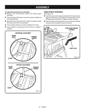
... the saw . English HORIZONTAL ADJUSTMENT RIVING KNIFE FRAMING SQUARE PUSH STICK STORAGE See Figure 18. Insert the push stick storage screws from the loose parts bag into the holes on the side of the saw table.
... the saw . English HORIZONTAL ADJUSTMENT RIVING KNIFE FRAMING SQUARE PUSH STICK STORAGE See Figure 18. Insert the push stick storage screws from the loose parts bag into the holes on the side of the saw table.
Operation Manual
Page 37
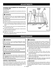
...to permit the rip fence to damage from various types of the unit under normal operating conditions. DO NOT use only identical replacement parts. Use of injury, always maintain proper rip fence alignment. Unplug the saw blade and the miter gauge grooves. GENERAL ...MAINTENANCE LUBRICATION Avoid using solvents when cleaning plastic parts. Use clean cloths to provide smooth functioning. Protect the blade by their use. Failure to heed this tool are susceptible to...
...to permit the rip fence to damage from various types of the unit under normal operating conditions. DO NOT use only identical replacement parts. Use of injury, always maintain proper rip fence alignment. Unplug the saw blade and the miter gauge grooves. GENERAL ...MAINTENANCE LUBRICATION Avoid using solvents when cleaning plastic parts. Use clean cloths to provide smooth functioning. Protect the blade by their use. Failure to heed this tool are susceptible to...

Parts Diagram
Page 3
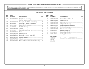
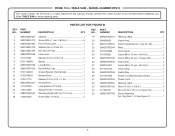
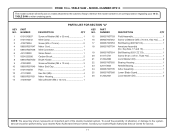
...Label (Upper Barrier 1 53 089037007911 Inner Guard Warning Label 1 54 089110113913 No Hands Warning Label 2 55 089037007909 Blade Guard Warning Label - PARTS LIST FOR FIGURE A KEY PART KEY PART NO. NUMBER DESCRIPTION QTY 1 089037007713 Throat Plate Assembly 1 2 089015001001 Screw (M8 x 30 mm 1 3 089015001013 Screw (M8 x 35 ... RTS10 The model number will be found on a label attached to the cabinet. TABLE SAW or when ordering parts. RYOBI 10 in. Right 1 56 089037007910 Blade Guard Warning Label - TABLE SAW - NUMBER DESCRIPTION QTY NO.
...Label (Upper Barrier 1 53 089037007911 Inner Guard Warning Label 1 54 089110113913 No Hands Warning Label 2 55 089037007909 Blade Guard Warning Label - PARTS LIST FOR FIGURE A KEY PART KEY PART NO. NUMBER DESCRIPTION QTY 1 089037007713 Throat Plate Assembly 1 2 089015001001 Screw (M8 x 30 mm 1 3 089015001013 Screw (M8 x 35 ... RTS10 The model number will be found on a label attached to the cabinet. TABLE SAW or when ordering parts. RYOBI 10 in. Right 1 56 089037007910 Blade Guard Warning Label - TABLE SAW - NUMBER DESCRIPTION QTY NO.
Parts Diagram
Page 4
...a label attached to the cabinet. Key Nos. 51-56 1 58 080015001437 Screw (1/4-20 x 3-1/4 in . TABLE SAW or when ordering parts. NUMBER DESCRIPTION QTY KEY PART NO. Always mention the model number in all correspondence regarding your 10 in , Hex Hd 2 59 410162003 Screw (M6 x 18 mm... Wrench (Open End 1 79 0101140903 Hex Key (M5 x 75 mm 1 Not Shown: 987000864 Operator's Manual (089037008193 1 3-8-17 (Rev:04) 4 PARTS LIST FOR FIGURE A KEY PART NO. NUMBER DESCRIPTION QTY 57 089037007700 Blade Guard Assembly (Inc...
...a label attached to the cabinet. Key Nos. 51-56 1 58 080015001437 Screw (1/4-20 x 3-1/4 in . TABLE SAW or when ordering parts. NUMBER DESCRIPTION QTY KEY PART NO. Always mention the model number in all correspondence regarding your 10 in , Hex Hd 2 59 410162003 Screw (M6 x 18 mm... Wrench (Open End 1 79 0101140903 Hex Key (M5 x 75 mm 1 Not Shown: 987000864 Operator's Manual (089037008193 1 3-8-17 (Rev:04) 4 PARTS LIST FOR FIGURE A KEY PART NO. NUMBER DESCRIPTION QTY 57 089037007700 Blade Guard Assembly (Inc...
Parts Diagram
Page 6
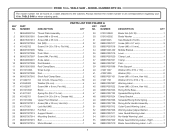
Always mention the model number in all correspondence regarding your 10 in . RYOBI 10 in . NUMBER DESCRIPTION QTY 1 089037007037 Cabinet 1 2 080015001473 Screw (M4 x 7 mm, Flat Hd 6 3 089037007904 Front Panel Label 1 4 080015001475 Washer (D6.5 x ...x 1-3/8 in 4 34 411062701 Nut (1/4-20 x 10 mm, Cheese Hd 4 35 089037007708 Stand Assembly (Inc. TABLE SAW or when ordering parts. NUMBER DESCRIPTION QTY KEY PART NO. MODEL NUMBER RTS10 The model number will be found on a label attached to the cabinet. TABLE SAW - Key Nos. 1-8, See ...
Always mention the model number in all correspondence regarding your 10 in . RYOBI 10 in . NUMBER DESCRIPTION QTY 1 089037007037 Cabinet 1 2 080015001473 Screw (M4 x 7 mm, Flat Hd 6 3 089037007904 Front Panel Label 1 4 080015001475 Washer (D6.5 x ...x 1-3/8 in 4 34 411062701 Nut (1/4-20 x 10 mm, Cheese Hd 4 35 089037007708 Stand Assembly (Inc. TABLE SAW or when ordering parts. NUMBER DESCRIPTION QTY KEY PART NO. MODEL NUMBER RTS10 The model number will be found on a label attached to the cabinet. TABLE SAW - Key Nos. 1-8, See ...
Parts Diagram
Page 7
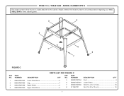
TABLE SAW or when ordering parts. 3 4 2 8 1 6 5 7 FIGURE C PARTS LIST FOR FIGURE C KEY PART NO. TABLE SAW - NUMBER DESCRIPTION QTY KEY PART NO. MODEL NUMBER RTS10 The model number will be found on a label attached to the cabinet. RYOBI 10 in . NUMBER DESCRIPTION QTY 1 089037007093 Lower Side Brace 2 2 089037007089 Leg 4 3 089037007088 Upper Brace 2 4 089037007090 Upper Side Brace...
TABLE SAW or when ordering parts. 3 4 2 8 1 6 5 7 FIGURE C PARTS LIST FOR FIGURE C KEY PART NO. TABLE SAW - NUMBER DESCRIPTION QTY KEY PART NO. MODEL NUMBER RTS10 The model number will be found on a label attached to the cabinet. RYOBI 10 in . NUMBER DESCRIPTION QTY 1 089037007093 Lower Side Brace 2 2 089037007089 Leg 4 3 089037007088 Upper Brace 2 4 089037007090 Upper Side Brace...
Parts Diagram
Page 8
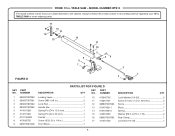
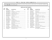
RYOBI 10 in . TABLE SAW or when ordering parts. FIGURE D 17 15 14 16 13 12 11 10 9 8 7 5 46 3 1 2 PARTS LIST FOR FIGURE D KEY PART NO. Always mention the model number in all correspondence regarding your 10 in . NUMBER DESCRIPTION QTY KEY PART NO. MODEL NUMBER RTS10 The model number will be found on a label attached...
RYOBI 10 in . TABLE SAW or when ordering parts. FIGURE D 17 15 14 16 13 12 11 10 9 8 7 5 46 3 1 2 PARTS LIST FOR FIGURE D KEY PART NO. Always mention the model number in all correspondence regarding your 10 in . NUMBER DESCRIPTION QTY KEY PART NO. MODEL NUMBER RTS10 The model number will be found on a label attached...
Parts Diagram
Page 9
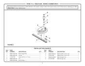
TABLE SAW or when ordering parts. 9 8 7 6 5 4 FIGURE E 3 1 2 PARTS LIST FOR FIGURE E KEY PART NO. NUMBER DESCRIPTION QTY 1 089015001009 Miter Gauge Rod 1 2 080015001563 Pointer 1 3 410332701 Screw (3/16 in 1 4 089015001010 Pin 1 5 089037007086 Miter Gauge 1 6 080015001475 Washer (D6.5 x D16 x 2t 1 7 412012003 ... regarding your 10 in . TABLE SAW - MODEL NUMBER RTS10 The model number will be found on a label attached to the cabinet. NUMBER DESCRIPTION QTY KEY PART NO. RYOBI 10 in .
TABLE SAW or when ordering parts. 9 8 7 6 5 4 FIGURE E 3 1 2 PARTS LIST FOR FIGURE E KEY PART NO. NUMBER DESCRIPTION QTY 1 089015001009 Miter Gauge Rod 1 2 080015001563 Pointer 1 3 410332701 Screw (3/16 in 1 4 089015001010 Pin 1 5 089037007086 Miter Gauge 1 6 080015001475 Washer (D6.5 x D16 x 2t 1 7 412012003 ... regarding your 10 in . TABLE SAW - MODEL NUMBER RTS10 The model number will be found on a label attached to the cabinet. NUMBER DESCRIPTION QTY KEY PART NO. RYOBI 10 in .
Parts Diagram
Page 11
MODEL NUMBER RTS10 The model number will be found on a label attached to the system, service should be performed by your nearest Ryobi Authorized Service Center. NUMBER DESCRIPTION QTY KEY PART NO. To avoid the possibility of the double insulated system. Always mention the model number in . Contact your 10 in all correspondence...
MODEL NUMBER RTS10 The model number will be found on a label attached to the system, service should be performed by your nearest Ryobi Authorized Service Center. NUMBER DESCRIPTION QTY KEY PART NO. To avoid the possibility of the double insulated system. Always mention the model number in . Contact your 10 in all correspondence...
Parts Diagram 1
Page 3
TABLE SAW or when ordering parts. PARTS LIST FOR FIGURE A KEY PART KEY PART NO. MODEL NUMBER RTS10G The model number will be found on a label attached to the cabinet. Left 1 3 Always mention the model number in all correspondence ... 1 19 414011001 Spring Pin (D4 x 13 mm 2 20 410162701 Screw (1/4-20 x 3/4 in . TABLE SAW - NUMBER DESCRIPTION QTY NO. Right 1 56 089037007910 Blade Guard Warning Label - RYOBI 10 in.
TABLE SAW or when ordering parts. PARTS LIST FOR FIGURE A KEY PART KEY PART NO. MODEL NUMBER RTS10G The model number will be found on a label attached to the cabinet. Left 1 3 Always mention the model number in all correspondence ... 1 19 414011001 Spring Pin (D4 x 13 mm 2 20 410162701 Screw (1/4-20 x 3/4 in . TABLE SAW - NUMBER DESCRIPTION QTY NO. Right 1 56 089037007910 Blade Guard Warning Label - RYOBI 10 in.

Parts Diagram 1
Page 4
TABLE SAW or when ordering parts. MODEL NUMBER RTS10G The model number will be found on a label attached to the cabinet. Always mention the model number in all correspondence regarding your 10 in . RYOBI 10 in . Key Nos. 51-56 1 58 080015001437 ... Hex Hd 1 67 089037007030 Indicator Bracket 1 68 089037007032 Indicator 1 69 089110101066 Screw w/Washer (M4 x 12 mm, Pan Hd.) ........1 KEY PART NO. NUMBER DESCRIPTION QTY 57 089037007700 Blade Guard Assembly (Inc. TABLE SAW - NUMBER DESCRIPTION QTY 70 089037007102 Washer (D6.5 x D20 x 1....
TABLE SAW or when ordering parts. MODEL NUMBER RTS10G The model number will be found on a label attached to the cabinet. Always mention the model number in all correspondence regarding your 10 in . RYOBI 10 in . Key Nos. 51-56 1 58 080015001437 ... Hex Hd 1 67 089037007030 Indicator Bracket 1 68 089037007032 Indicator 1 69 089110101066 Screw w/Washer (M4 x 12 mm, Pan Hd.) ........1 KEY PART NO. NUMBER DESCRIPTION QTY 57 089037007700 Blade Guard Assembly (Inc. TABLE SAW - NUMBER DESCRIPTION QTY 70 089037007102 Washer (D6.5 x D20 x 1....
Parts Diagram 1
Page 6
... 1 31 089037007114 Power Cord 1 32 089037007902 Warning Label 1 33 089037007105 Bolt (1/4-20 x 1-3/8 in . Key Nos. 1-8, See Figure C 1 6 NUMBER DESCRIPTION QTY KEY PART NO. PARTS LIST FOR FIGURE B KEY PART NO. NUMBER DESCRIPTION QTY 1 089040002002 Cabinet 1 2 080015001473 Screw (M4 x 7 mm, Flat Hd 6 3 089040002902 Front Panel Label 1 4 080015001475 Washer (D6.5 x D16x... in 4 34 411062701 Nut (1/4-20 x 10 mm, Cheese Hd 4 35 089037007708 Stand Assembly (Inc. TABLE SAW or when ordering parts. RYOBI 10 in.
... 1 31 089037007114 Power Cord 1 32 089037007902 Warning Label 1 33 089037007105 Bolt (1/4-20 x 1-3/8 in . Key Nos. 1-8, See Figure C 1 6 NUMBER DESCRIPTION QTY KEY PART NO. PARTS LIST FOR FIGURE B KEY PART NO. NUMBER DESCRIPTION QTY 1 089040002002 Cabinet 1 2 080015001473 Screw (M4 x 7 mm, Flat Hd 6 3 089040002902 Front Panel Label 1 4 080015001475 Washer (D6.5 x D16x... in 4 34 411062701 Nut (1/4-20 x 10 mm, Cheese Hd 4 35 089037007708 Stand Assembly (Inc. TABLE SAW or when ordering parts. RYOBI 10 in.


